Advertisement
Quick Links
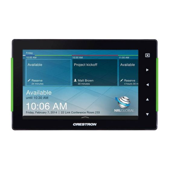
TSS-752
7" Room Scheduling Touch Screen
1
Install the Touch Screen
The Crestron
®
TSS-752 touch screen installs into a standard 2-gang
(or horizontally mounted 1-gang) U.S electrical box, a 2-gang
European electrical box, a 2-gang UK electrical box. It can also
install over a small cutout (for Ethernet access) on virtually any
mounting surface.
To mount the TSS-752 into an electrical box, use the following
procedure:
1. Use four of the eight included screws (four #06-32 x 3/4" or four
3 x 16 mm) to attach the mounting plate (4519681 or 4519719)
to the electrical box, as shown in the following illustration.
For U.S.-style installations, use the #06-32 x 3/4" screws
(2033247).
For European-style installations, use the 3 x 16 mm screws
(2013788).
NOTE: For U.S.-style installations, use a #2 Phillips
screwdriver. For European-style installations, use a #1
Phillips screwdriver or equivalent.
Attach the Mounting Plate to a U.S. Electrical Box
U.S. Electrical Box
Mounting Plate
(4519719)
Screws (4) #06-32 x 3/4"
(2033247)
1
For regulatory compliance information, refer to Doc. 7601.
QUICKSTART DOC. 7600C (2038155, Sheet 1 of 2)
2. Gently snap the two mounting plate covers (2037956 or
2037961) into place to hide the screws to the electrical box.
Attach the Mounting Plate Covers
Mounting Plate
(4519719)
Mounting Plate Covers (2)
(2037956 or 2037961)
3. Carefully position the TSS-752 over the mounting plate to
engage the four screws protruding from the plate. Slide the
TSS-752 to the left until it clicks into place.
Attach the TSS-752 to the Mounting Plate
Mounting Plate
(4519719)
TSS-752
www.crestron.com
888.273.7876
04.14
Specifications subject to
change without notice.
NOTE: It some situations where there may not be enough
room to slide the TSS-752 from right to left on the mounting
plate, the plate can be installed with the locking tabs on the
left side. In such cases, attach the TSS-752 by sliding it to
the right until it clicks into place.
4. When making connections to the TSS-752, use Crestron power
supplies for Crestron equipment. Apply power after all
connections have been made.
Hardware Connections for the TSS-752
10BASE-T / 100BASE-TX
Continued on following page
201.767.3400
Reset Button
LAN PoE:
Ethernet to LAN
Advertisement

Related Manuals for Crestron TSS-752


Summary of Contents for Crestron TSS-752
- Page 1 (or horizontally mounted 1-gang) U.S electrical box, a 2-gang 2037961) into place to hide the screws to the electrical box. room to slide the TSS-752 from right to left on the mounting European electrical box, a 2-gang UK electrical box. It can also...
- Page 2 Scheduling “Offline” screen, same time, slide the TSS-752 to the right about 1/4” (~7 mm) to unlock it from the mounting plate. touch “hard keys” 1, 2, 3 and 4, to the right of the touch screen display, in sequence twice (touch Remove the TSS-752 from the Mounting Plate 1, 2, 3, 4, 1, 2, 3, 4) within a five second period.
- Page 3 TSS-752 7” Room Scheduling Touch Screen Dimensions Pinout Reference TSS-752 Overall Dimensions (Top View) The only connector on the TSS-752 is the LAN PoE port. 6.28 in (160 mm) LAN PoE Pin 1 Pin 8 1.20 in 1.25 in 1.41 in 1.47 in...
-
Page 4: Specifications
Crestron Electronics, Inc. in the United States and/or other countries. Other trademarks, registered trademarks and trade names may be used in this document to refer to either the entities claiming the marks and names or their products. Crestron disclaims any proprietary interest in the marks and names of others.