Table of Contents
Advertisement
Quick Links
Advertisement
Table of Contents

Related Manuals for Crestron TST-1080


Summary of Contents for Crestron TST-1080
- Page 1 TST-1080 10.1 in. Wireless Touch Screen Product Manual Crestron Electronics, Inc.
- Page 2 Alliance in the United States and/or other countries. Other trademarks, registered trademarks, and trade names may be used in this document to refer to either the entities claiming the marks and names or their products. Crestron disclaims any proprietary interest in the marks and names of others. Crestron is not responsible for errors in typography or photography.
-
Page 3: Table Of Contents
Contents Overview Features TST-1080 Features TST-1080-DS Features TST-1080-DSW Features TST-902-DSW-BB Features TST-902-DSW-BBI Features TST-902-DSW-PMK Features TST-902-DSW-WMKM Features TST-902-DSW-WMKT Features Specifications TST-1080 Specifications Product Specifications Dimension Drawings TST-1080-DS Specifications Product Specifications Dimension Drawings TST-1080-DSW Specifications Product Specifications Dimension Drawings TST-902-DSW-BB Specifications... - Page 4 Charge the Battery Place the Touch Screen TST-1080-DS Installation In the Box Install the TST-1080-DS TST-1080-DSW Installation In the Box Install the Mounting Hardware Install the TST-1080-DSW Dock the Touch Screen Undock the Touch Screen TST-902-DSW-BB Installation In the Box...
- Page 5 Operation Resources Crestron Support and Training Programmer and Developer Resources Product Certificates Related Documentation Product Manual — Doc. 9338A Contents • v...
-
Page 6: Overview
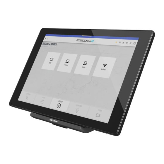
Overview The Crestron® wireless touch screen is an advanced wireless controller, engineered to deliver ultimate performance, reliability, and customization for controlling a wide range of technologies. Its thin, tablet-style design makes it easy to hold and allows it to move effortlessly between portable and stationary use. -
Page 7: Features
Features This section provides the following information: • TST-1080 Features • TST-1080-DS Features • TST-1080-DSW Features • TST-902-DSW-BB Features • TST-902-DSW-BBI Features • TST-902-DSW-PMK Features • TST-902-DSW-WMKM Features • TST-902-DSW-WMKT Features 2 • TST-1080 Product Manual — Doc. 9338A... -
Page 8: Tst-1080 Features
TST-1080 Features The Crestron® wireless touch screen is an advanced wireless controller, engineered to deliver ultimate performance, reliability, and customization for controlling a wide range of technologies. Its thin, tablet-style design makes it easy to hold and allows it to move effortlessly between portable and stationary use. - Page 9 Wall dock option sold separately Custom-Programmable Virtual Buttons The TST-1080-DSW provides a universal status bar that is populated with virtual buttons for quick access to common touch screen functions. The touch screen comes preconfigured with virtual buttons for Power, Home, Lights, Up, Down, and Microphone. Each button can be programmed via a Crestron control system to provide custom functionality, and unused buttons can be hidden individually.
- Page 10 A TST-1080 can be installed in each room to provide easy access to various Crestron Home functions for both the room and the home.
- Page 11 Extended Battery Life The TST-1080 features a large-capacity Lithium Ion battery pack that allows for up to nine hours of continuous operation and several days of typical use between charges. Intelligent power management and Lithium Ion battery technology work together to provide a lightweight, compact battery with long battery life.
- Page 12 TST-1080 to be used as a stationary tabletop touch screen. The table dock holds the TST-1080 firmly at a fixed upright angle while docked, and allows it to be taken off at any time for portable use. Its sleek appearance makes it a perfect fit for any home or office.
-
Page 13: Tst-1080-Ds Features
The table dock also allows the TST-1080 to be used as a stationary tabletop touch screen. The table dock holds the TST-1080 firmly at a fixed upright angle while docked, and allows it to be taken off at any time for portable use. Its sleek appearance makes it a perfect fit for any home or office. -
Page 14: Tst-1080-Dsw Features
TST-1080 wireless touch screen. Placing the TST-1080 into the wall dock allows it to be used as a stationary touch screen while simultaneously charging its internal battery. When docked in the TST-1080-DSW, the touch screen sits nearly flush with the outer bezel, affording a clean appearance while preventing unauthorized removal. -
Page 15: Tst-902-Dsw-Bb Features
Note: 1. The TST-1080-DSW docking mechanism works as intended when mounted in a standard vertical orientation (such as within a wall). The maximum allowable tilt is 16° back. The mechanism will not eject properly at an angle greater than this. -
Page 16: Specifications
Specifications This section provides the following information: • TST-1080 Specifications • TST-1080-DS Specifications • TST-1080-DSW Specifications • TST-902-DSW-BB Specifications • TST-902-DSW-BBI Specifications • TST-902-DSW-PMK Specifications • TST-902-DSW-WMKM Specifications • TST-902-DSW-WMKT Specifications Product Manual — Doc. 9338A TST-1080 • 11... -
Page 17: Tst-1080 Specifications
Graphics Engine Crestron HTML5 User Interface technology, multilanguage web browser , multilanguage on-screen keyboard, screensaver, native Crestron Home® OS app, setup and diagnostics via web browser, cloud, or on-screen UI Languages Crestron HTML5 User Arabic, Chinese (Simplified), Chinese (Traditional), Czech, Danish, Dutch,... - Page 18 Built-in microphone and speakers, Rava® SIP intercom, multilanguage voice recognition Audio Feedback Formats Connectors Docking Connector (3) Contacts; Mates with docking port on included TST-1080-DS docking station (1) Type-C USB port; For charging touch screen battery Power Product Manual — Doc. 9338A TST-1080 • 13...
- Page 19 Weight 1.7 lb (780 g) Compliance Regulatory Model: M202215001; IC, CE, FCC Part 15 Class B digital device To search for product certificates, refer to support.crestron.com/app/certificates. Notes: 1. The TST-1080 ships with one TST-1080-DS table dock included. Additional table docks, or the...
-
Page 20: Dimension Drawings
(WAPs). The last successful Wi-Fi connection is maintained indefinitely until that connection is lost, at which point communication is handed off to the nearest available WAP. A very brief interruption to wireless Ethernet communication may occur during the handoff. Dimension Drawings Product Manual — Doc. 9338A TST-1080 • 15... -
Page 21: Tst-1080-Ds Specifications
TST-1080-DS Specifications Refer to the following product specifications for the TST-1080-DS. Product Specifications Connectors Power (1) Attached 6 ft (1.83 m) cable with inline 2.1 x 5.5 mm DC power connector; 24VDC power input (for included power pack) Power Power Pack (Included) Input: 0.8A (maximum) @ 100–240VAC, 50/60 Hz;... -
Page 22: Dimension Drawings
Dimension Drawings Product Manual — Doc. 9338A TST-1080 • 17... -
Page 23: Tst-1080-Dsw Specifications
) maximum Controls OPEN (1) Push button, accessible when touch screen is not docked; Releases the docking mechanism that allows the TST-1080 to be docked Power Requirements Cresnet® Power Usage 30 W (1.25A @ 24VDC) with touch screen docked NOTE: May be powered by Cresnet® network power or a dedicated Cresnet power supply. Does not support Cresnet data communication (only power). - Page 24 To search for product certificates, refer to support.crestron.com/app/certificates. Note: 1. The TST-1080-DSW docking mechanism works as intended when mounted in a standard vertical orientation (such as within a wall). The maximum allowable tilt is 16° back. The mechanism will not eject properly at an angle greater than this.
-
Page 25: Dimension Drawings
Dimension Drawings 20 • TST-1080 Product Manual — Doc. 9338A... -
Page 26: Tst-902-Dsw-Bb Specifications
Metal box, front mounting plate with integral stud mounting flange, metal cover plate Dimensions Height 9.01 in. (229 mm) Width 13.65 in. (347 mm) Depth 3.32 in. (85 mm) To search for product certificates, refer to support.crestron.com/app/certificates. Dimension Drawings Product Manual — Doc. 9338A TST-1080 • 21... -
Page 27: Tst-902-Dsw-Bbi Specifications
Refer to the following product specifications for the TST-902-DSW-BBI. Product Specifications Construction Metal box Dimensions Height 197 mm (7.74 in.) Width 281 mm (11.05 in.) Depth 91 mm (3.56 in.) To search for product certificates, refer to support.crestron.com/app/certificates. Dimension Drawings 22 • TST-1080 Product Manual — Doc. 9338A... -
Page 28: Tst-902-Dsw-Pmk Specifications
Product specifications for the TST-902-DSW-PMK are provided below. Product Specifications Construction Metal mounting plate and cover plate Dimensions Height 8.82 in. (224 mm) Width 13.59 in. (346 mm) To search for product certificates, refer to support.crestron.com/app/certificates. Dimension Drawings Product Manual — Doc. 9338A TST-1080 • 23... -
Page 29: Tst-902-Dsw-Wmkm Specifications
Product specifications for the TST-902-DSW-WMKM are provided below. Product Specifications Construction Metal mounting plate and mud ring Dimensions Height 8.82 in. (224 mm) Width 12.46 in. (316 mm) To search for product certificates, refer to support.crestron.com/app/certificates. 24 • TST-1080 Product Manual — Doc. 9338A... -
Page 30: Dimension Drawings
Dimension Drawings Product Manual — Doc. 9338A TST-1080 • 25... -
Page 31: Tst-902-Dsw-Wmkt Specifications
Product specifications for the TST-902-DSW-WMKT are provided below. Product Specifications Construction Metal mounting plate and trim ring Dimensions Height 8.82 in. (224 mm) Width 12.00 in. (305 mm) To search for product certificates, refer to support.crestron.com/app/certificates. 26 • TST-1080 Product Manual — Doc. 9338A... -
Page 32: Dimension Drawings
Dimension Drawings Product Manual — Doc. 9338A TST-1080 • 27... -
Page 33: Installation
Installation This section provides the following information: • TST-1080 Installation • TST-1080-DS Installation • TST-1080-DSW Installation • TST-902-DSW-BB Installation • TST-902-DSW-BBI Installation • TST-902-DSW-PMK Installation • TST-902-DSW-WMKM Installation • TST-902-DSW-WMKT Installation 28 • TST-1080 Product Manual — Doc. 9338A... -
Page 34: Tst-1080 Installation
Use the following procedures to install the TST-1080. Compliance and Safety Review the following compliance and safety statements before installing the TST-1080. Lithium-Ion Battery Pack Statement The device ships with an internal Lithium-Ion battery installed. The battery is specific to this device and is not user replaceable. -
Page 35: In The Box
Power Pack, 24VDC @ 1.25A, 100–240VAC (2045870) Charge the Battery The TST-1080 ships in low power mode to conserve the battery charge. The TST-1080 battery must be charged fully before configuring and operating the touch screen for the first time. The TST-1080 battery can be charged using one of the following methods: Place the TST-1080 into its included table dock (TST-1080-DS) or the optional wall dock (TST-1080-DSW, not included) after installing and applying power to the dock. -
Page 36: Place The Touch Screen
Place the Touch Screen The TST-1080 can be used as a portable tablet-style device, or it can it can be placed within the included table dock or optional wall dock for use as a stationary touch screen. -
Page 37: Tst-1080-Ds Installation
Power Pack, 24VDC @ 1.25A, 100–240VAC (2045870) Install the TST-1080-DS Place the TST-1080-DS on a flat, level surface. The only required connection is from the fixed 6 ft (1.83 m) power cord on the TST-1080-DS to the included power pack. 32 • TST-1080... - Page 38 Use Crestron power supplies for Crestron equipment. The included power cord cannot be extended. After power has been applied to the TST-1080-DS, place the TST-1080 touch screen on the TST-1080-DS by aligning its three charging contacts with the bottom of the charging dock. The touch screen should be seated firmly on the charging dock once attached, and the touch screen battery will begin to charge.
-
Page 39: Tst-1080-Dsw Installation
Install the Mounting Hardware One of the available TST-1080-DSW mounting accessories (not included) must be installed prior to installing the TST-1080-DSW. Refer to the following installation procedures depending on the chosen mounting hardware: NOTE: Ensure the chosen mounting location allows for an air gap of at least 12 in. (305 mm) in the wall cavity above and below the TST-1080-DSW for heat dissipation. -
Page 40: Install The Tst-1080-Dsw
NOTE: The maximum wire size for the power connection is 18 AWG. 2. While holding the TST-1080-DSW, connect the flying leads from the wiring to the 2-pin power connector (24 G) on the rear of the TST-1080-DSW. Product Manual — Doc. 9338A... - Page 41 The following illustration shows the TST-1080-DSW being attached to the TST-902-DSW-BB back box as an example. NOTES: The cradle for the touch screen on the TST-1080-DSW should be in the closed position during installation. Do not overtighten the screws. The screws should be hand tightened or machine tightened to no more than 5 in-lb torque.
- Page 42 NOTE: If the bezel must be removed for any reason, disconnect this cable carefully prior to removal. 5. Attach the bezel to the TST-1080-DSW using the four 6-32 x 1 in. screws, but do not tighten the screws. Refer to the illustration below step 7.
- Page 43 Then, tighten the screws fully to secure the bezel. NOTE: Do not overtighten the screws. The screws should be hand tightened or machine tightened to no more than 5 in-lb torque. 38 • TST-1080 Product Manual — Doc. 9338A...
-
Page 44: Dock The Touch Screen
Then, push the cradle back into place to close it. Dock the Touch Screen To dock the TST-1080 touch screen once the TST-1080-DSW has been installed: 1. Push the release button on the right of the bezel to open the cradle. -
Page 45: Undock The Touch Screen
1. Insert the provided release lock key into the gap between the top of the touch screen and the TST-1080-DSW. Ensure that the machined text on the key is facing upward. 2. Rotate the key downward as shown in the following illustration. - Page 46 3. Remove the key to open the cradle so that the touch screen can be removed. Product Manual — Doc. 9338A TST-1080 • 41...
-
Page 47: Tst-902-Dsw-Bb Installation
NOTES: Ensure the chosen mounting location allows for an air gap of at least 12 in. (305 mm) in the wall cavity above and below the TST-1080-DSW for heat dissipation. Depending on the installation, forced venting may be required. The knockout holes are intended for Class 2 wiring and are 1-1/8 in. (29 mm) in diameter. - Page 48 3. Verify that the back box is level prior to proceeding with the rest of the installation. 4. Attach the TST-902-DSW-BB to the left or right side of the stud with four standard drywall screws or nails (not included). Product Manual — Doc. 9338A TST-1080 • 43...
- Page 49 5. Install the 8-8B x 1/4 in. self-tapping screw in the rear of the back box mounting enclosure as shown in the following illustration. 6. Route any wiring for the TST-1080-DSW through the appropriate knockout(s) on the back box. 7. Once drywall is installed over the back box, use a standard drywall saw to cut the drywall along the inside edge of the front of the back box.
- Page 50 NOTE: The four tapped holes on the front of the back box must be exposed in order to accept the TST-1080-DSW mounting screws. These holes are located along the top and bottom of the drywall opening. The notch at the top center of the back box must also be exposed to accommodate the TST-1080-DSW locking latch.
- Page 51 9. Remove the cover plate and 6-32 x 1-1/2 in. screws (if used), and then install the TST-1080-DSW wall dock into the TST-902-DSW-BB as described in Install the TST-1080-DSW on page 35 with the 6-32 x 1-1/2 in. screws. 46 • TST-1080 Product Manual — Doc. 9338A...
-
Page 52: Tst-902-Dsw-Bbi Installation
1. Remove the appropriate knockout(s) on the TST-902-DSW-BBI for routing wiring to the TST-1080-DSW wall dock. 2. Route any wiring for the TST-1080-DSW through the appropriate knockout(s) on the back box. 3. Use the dimensions listed within TST-902-DSW-BBI Specifications on page 22 to create an appropriately sized cutout in the mounting surface. - Page 53 5. Install the TST-1080-DSW wall dock into the TST-902-DSW-BBI as described in Install the TST-1080-DSW on page 35 using the included 6-32 x 1-1/2 in. screws. 48 • TST-1080 Product Manual — Doc. 9338A...
-
Page 54: Tst-902-Dsw-Pmk Installation
Ensure the chosen mounting location allows for an air gap of at least 12 in. (305 mm) in the wall cavity above and below the TST-1080-DSW for heat dissipation. The wire jumper is intended to hang wires during installation to keep them away from any cutting tools and should be secured in the mounting bracket as described in the following procedure. - Page 55 2. Verify that the mounting bracket is level prior to proceeding with the rest of the installation. 3. Attach the mounting bracket to the left or right side of the stud with two standard drywall screws or nails (not included). 50 • TST-1080 Product Manual — Doc. 9338A...
- Page 56 4. Secure the wire jumper to the bottom of the mounting bracket as shown in the following illustration. 5. Route any wiring for the TST-1080-DSW through the opening in the mounting bracket and secure them into the wire jumper. Product Manual — Doc. 9338A...
- Page 57 NOTE: The four tapped holes on the front of the mounting bracket must be exposed in order to accept the TST-1080-DSW mounting screws. These holes are located along the top and bottom of the drywall opening. The notch at the top center of the mounting bracket must also be exposed to accommodate the TST-1080-DSW locking...
- Page 58 7. (Optional) If required by local building codes, use the 6-32 x 1-1/2 in. screws to install the included cover plate over the mounting bracket. The cover plate should remain attached until the TST-1080-DSW is installed. Product Manual — Doc. 9338A TST-1080 • 53...
- Page 59 8. Remove the cover plate and 6-32 x 1-1/2 in. screws (if used), and then install the TST-1080-DSW wall dock into the mounting bracket as described in Install the TST-1080-DSW on page 35 with the 6-32 x 1-1/2 in. screws. 54 • TST-1080 Product Manual — Doc. 9338A...
-
Page 60: Tst-902-Dsw-Wmkm Installation
Use the following procedures to install the TST-902-DSW-WMKM. NOTE: The TST-902-DSW-WMKM postconstruction wall mount kit is a TST-902-DSW and TST-1080-DSW mounting accessory that is designed for postconstruction applications where mounting hardware will be installed in an existing framed wall or similar flat surface using a mud ring. - Page 61 Additionally, a cutout template is provided with the TST-902-DSW-WMKM that can be used when making the drywall cutout for the mounting hardware. The dimensions for the cutout template are provided below as a reference (not to scale). 56 • TST-1080 Product Manual — Doc. 9338A...
-
Page 62: Install The Mounting Kit
NOTES: Ensure the chosen mounting location allows for an air gap of at least 12 in. (305 mm) in the wall cavity above and below the TST-1080-DSW for heat dissipation. The TST-902-DSW-WMKM has been optimized for mounting into drywall that is 5/8 in. (15 mm) thick, though it can also be mounted into drywall that is between 1/2 in. - Page 63 5. Using a drywall saw (or equivalent), a level, and the provided cutout template, create a cutout in the drywall for the mounting hardware. Refer to the illustration in Prepare for Installation on page 55 for cutout dimensions. 58 • TST-1080 Product Manual — Doc. 9338A...
- Page 64 NOTE: Ensure that the cutout is as level and smooth as possible before proceeding. The mounting plate allows only for minor adjustments once installed. 6. Insert the mud ring into the drywall cutout. Product Manual — Doc. 9338A TST-1080 • 59...
- Page 65 Refer to the following illustration. NOTE: The mounting plate and adjustment plate assembly has a slight amount of play. This is normal, as it allows for minor adjustments to be made to the TST-1080-DSW during installation. 60 • TST-1080 Product Manual — Doc. 9338A...
- Page 66 9. Use four standard drywall screws to loosely secure the mud ring to the mounting plate and adjustment plate assembly. The screws must pass through the clearance holes in the mounting plate to be secured in the extruded holes of the adjustment plate. Product Manual — Doc. 9338A TST-1080 • 61...
- Page 67 10. Verify that the mounting hardware is level, and then hand tighten the drywall screws using a #2 Phillips screwdriver so that they dimple slightly into the holes in the mud ring. CAUTION: Do not overtighten the screws, as this may damage the mounting hardware. 62 • TST-1080 Product Manual — Doc. 9338A...
- Page 68 11. Route any wiring for the TST-1080-DSW through the opening in the mounting hardware. 12. Apply joint compound as needed to finish the cutout. Product Manual — Doc. 9338A TST-1080 • 63...
- Page 69 The notch at the top center of the mud ring must also be exposed to accommodate the TST-1080-DSW locking latch. 13. After the joint compound has dried, install the TST-1080-DSW wall dock into the mud ring as described in Install the TST-1080-DSW on page 35 with the 6-32 x 1-1/2 in.
-
Page 70: Tst-902-Dsw-Wmkt Installation
Use the following procedures to install the TST-902-DSW-WMKT. NOTE: The TST-902-DSW-WMKT postconstruction wall mount kit is a TST-902-DSW and TST-1080-DSW mounting accessory that is designed for postconstruction applications where mounting hardware will be installed in an existing framed wall or similar flat surface using a mud ring. - Page 71 Additionally, a cutout template is provided with the TST-902-DSW-WMKT that can be used when making the drywall cutout for the mounting hardware. The dimensions for the cutout template are provided below as a reference (not to scale). 66 • TST-1080 Product Manual — Doc. 9338A...
-
Page 72: Install The Mounting Kit
NOTES: Ensure the chosen mounting location allows for an air gap of at least 12 in. (305 mm) in the wall cavity above and below the TST-1080-DSW for heat dissipation. The TST-902-DSW-WMKT has been optimized for mounting into drywall that is 5/8 in. - Page 73 5. Once the mounting plate is in the correct position, bend the top two flanges of the mud ring upward (approximately 90 degrees) and the bottom two flanges downward (approximately 90 degrees) to secure them to the rear of the drywall. Refer to the following illustration. 68 • TST-1080 Product Manual — Doc. 9338A...
- Page 74 NOTE: The mounting plate has a slight amount of play. This is normal, as it allows for minor adjustments to be made to the TST-1080-DSW during installation. 6. Route any wiring for the TST-1080-DSW through the opening in the mounting hardware. Product Manual — Doc. 9338A...
- Page 75 7. Install the TST-1080-DSW wall dock into the trim ring as described in Install the TST-1080-DSW on page 35 with the 6-32 x 1-1/2 in. screws. 70 • TST-1080 Product Manual — Doc. 9338A...
-
Page 76: Configuration
Prior to configuration, ensure the device is running the latest firmware. To update the firmware, refer to Update Firmware on page This section provides the following information: • Initial Setup • Device Configuration • Perform a Factory Restore Product Manual — Doc. 9338A TST-1080 • 71... -
Page 77: Initial Setup
Use the following procedures to set up the TST-1080 after installation. Complete the Setup Wizard The TST-1080 provides a built-in setup wizard that is displayed after first applying power to the touch screen or after a restore. The setup wizard is used to configure various touch screen settings required for operation. - Page 78 Tap the desired time zone to select it. A filled radio button is shown next to the selected time zone. Tap Next to proceed to the next screen. Product Manual — Doc. 9338A TST-1080 • 73...
- Page 79 NOTE: Additional Wi-Fi network settings can be configured after completing the setup wizard, including the configuration of additional Wi-Fi network access points. For more information, refer to Network on page 102. Tap Next to proceed to the next screen. 74 • TST-1080 Product Manual — Doc. 9338A...
- Page 80 Tap the desired application to select it. A filled radio button is shown next to the application name once it is selected. Tap OK to complete the initial setup process. Product Manual — Doc. 9338A TST-1080 • 75...
-
Page 81: Access A Configuration Interface
The touch screen configuration interface is displayed with the Status tab shown and the Device accordion open by default. For more information on using the web configuration interface, refer Device Configuration on page 76 • TST-1080 Product Manual — Doc. 9338A... - Page 82 The touch screen configuration interface is displayed with the Status tab shown and the Device accordion open by default. For more information on using the local configuration interface, refer Device Configuration on page Product Manual — Doc. 9338A TST-1080 • 77...
-
Page 83: Create An Admin Account
The first time the web configuration interface is accessed, a page is displayed asking the user to create an admin account. A similar prompt is displayed when connecting to the touch screen via the local setup pages or in Crestron Toolbox software if an admin account has not already been created. -
Page 84: Set A Static Ip Address
The touch screen ships with DHCP turned on by default. To configure a static IP address for the touch screen: 1. Access the device configuration interface as described in Access a Configuration Interface on page 2. Navigate to Settings > Network. Product Manual — Doc. 9338A TST-1080 • 79... -
Page 85: Connect To The Xio Cloud Service
The touch screen is configured to connect to the service by default. NOTE: An XiO Cloud account is required to use the service. To register for an XiO Cloud account, refer to www.crestron.com/Support/Tools/Licensing-Registration/XiO-Account- Registration. 80 • TST-1080 Product Manual — Doc. 9338A... -
Page 86: Update Firmware
The MAC address and serial number are required to add the touch screen to the XiO Cloud service. 2. Log in to your XiO Cloud account at portal.crestron.io. 3. Claim the touch screen to the XiO Cloud service as described in the XiO Cloud User Guide. - Page 87 Select the x button to close the Firmware Update dialog box at any time during the update. Selecting the x button before the PUF is loaded to the touch screen cancels the update. 82 • TST-1080 Product Manual — Doc. 9338A...
-
Page 88: Device Configuration
NOTE: The web and local configuration interfaces are largely similar. Any differences will be noted throughout this section. Images show the web configuration interface unless noted otherwise. The Status tab is shown with the Device accordion open by default. Web Configuration Interface Product Manual — Doc. 9338A TST-1080 • 83... - Page 89 Select the profile button to see the active touch screen user and to sign out of the web configuration utility. Each section of the configuration interface is described in the sections that follow. 84 • TST-1080 Product Manual — Doc. 9338A...
-
Page 90: Action Menu
Save Changes button. Select Save Changes to save the setting. Saving certain changes will require the touch screen to be restarted. The Action menu provides the following selections. Save Changes Select Save Changes to save any changes made to the configuration settings. Product Manual — Doc. 9338A TST-1080 • 85... - Page 91 Select Download Logs to download the touch screen message logs for diagnostic purposes. The message files download as a compressed .tgz file. Once the compressed file is downloaded, extract the message log files to view them. 86 • TST-1080 Product Manual — Doc. 9338A...
- Page 92 Action column to delete the certificate. A dialog box is displayed asking whether the certificate should be deleted. Select Yes to delete the group or No to cancel deleting the group. Product Manual — Doc. 9338A TST-1080 • 87...
- Page 93 Select Local Setup to close the local configuration interface on the touch screen display and return to the selected application or user project. Enter Standby (Web Only) Select Enter Standby to force the touch screen to enter standby timeout mode. 88 • TST-1080 Product Manual — Doc. 9338A...
- Page 94 Select App Upgrade to update the currently selected application. The update progress is shown in a pop-up window. NOTE: This selection is not available if the touch screen is running in user project mode. Once the update is complete, select OK to close the pop-up window. Product Manual — Doc. 9338A TST-1080 • 89...
-
Page 95: Status
Select + More details at the bottom of the Device tab to display an expanded section that shows additional touch screen information. If + More Details is selected, select - Less details to collapse the section. 90 • TST-1080 Product Manual — Doc. 9338A... - Page 96 Wi-Fi network connection is inactive.) MAC Address: The unique MAC (media access control) address for the Wi-Fi network adapter. For more information on configuring network settings, refer to System Setup on page Product Manual — Doc. 9338A TST-1080 • 91...
- Page 97 IP ID: The IP ID used to connect the touch screen to the control system Room ID: The control system room ID that the touch screen is associated with (for connections to the Crestron Virtual Control server-based control system) IP Address/Hostname: The control system IP address or host name Type: The control system connection type...
- Page 98 Write Access Level: Indicates whether the user has write level permissions (true) or read-only permissions (false) Address: The IP address of the SNMP manager Authentication Protocol: The authentication protocol used by the SNMP manager Privacy Protocol: The privacy protocol used by the SNMP manager Product Manual — Doc. 9338A TST-1080 • 93...
-
Page 99: Settings
NOTE: If an invalid value is entered for a setting, the configuration interface will not allow changes to be saved until a valid value is entered. Red text is displayed next a setting to indicate an invalid value. 94 • TST-1080 Product Manual — Doc. 9338A... - Page 100 System Setup Select System Settings to configure general network and touch screen settings. System settings are grouped within subsections that can be expanded. The following System Settings configuration settings are provided. Product Manual — Doc. 9338A TST-1080 • 95...
- Page 101 Enter the NTP server address into the Address text field. Enter the NTP server port into the Port text field. Use the Authentication Method drop-down menu to select the authentication method used to access the NTP server (if one exists). 96 • TST-1080 Product Manual — Doc. 9338A...
- Page 102 Time: Select the time for the touch screen (in 24-hour format) using the pop-up menu that is displayed. Control System Select the + (plus) icon next to Control System to configure a connection to a Crestron control system. NOTE: The Control System settings are shown in user project mode only.
- Page 103 Room ID: Enter a room ID to associate with the touch screen (for connections with the Crestron Virtual Control server-based control system) NOTE: For more information on connecting the touch screen to Crestron Virtual Control, refer to the Crestron Virtual Control Server Software Product Manual.
- Page 104 Text Font Face: Use the drop-down menu to select a font for the screensaver text. Header Text Line 1: Enter text to be displayed on the first header text line of touch screen screensaver. Product Manual — Doc. 9338A TST-1080 • 99...
- Page 105 URL. Video URL: Enter a URL of video to be used by the touch screen screensaver. Logo Setting: Select one of the radio buttons (None, Crestron, and Custom) to select a logo type to use on the touch screen screensaver.
- Page 106 Enter "0" to turn off suspend mode timeout when the touch screen is undocked. NOTE: The Suspend Mode Timeout value should be set to at least 5 seconds greater than the Standby Timeout Undocked value. For more information, refer to Device Display on page Product Manual — Doc. 9338A TST-1080 • 101...
- Page 107 Primary Static DNS: Enter the primary DNS address used to resolve the touch screen domain to an IP address. Secondary Static DNS: Enter the secondary DNS address used to resolve the touch screen domain to an IP address. 102 • TST-1080 Product Manual — Doc. 9338A...
- Page 108 to view details about the Wi-Fi access point. Select Add to add a new entry to the Wi-Fi access point table. After selecting one more entries in the Wi-Fi access point table, select Remove to delete the selected entries. Product Manual — Doc. 9338A TST-1080 • 103...
- Page 109 HTTPS Proxy Port: Enter the port number of the HTTPS proxy server. Username: Enter the username required for the HTTPS proxy server. Password: Enter the password required for the HTTPS proxy server. 104 • TST-1080 Product Manual — Doc. 9338A...
- Page 110 Select Auto Update to configure automatic firmware updates for the touch screen. NOTE: The Auto Update accordion can be used to configure auto update settings for firmware only. Automatic application updates are not affected by these settings. Product Manual — Doc. 9338A TST-1080 • 105...
- Page 111 Custom URL: Turn on the toggle use a custom update server URL. If turned off, the server URL will default to the standard Crestron update sever. Custom URL Path: If Custom URL Path is turned on, enter the custom URL path for the update server.
- Page 112 NOTE: Each application uses a unique setup procedure for registering and configuring the application. Additional Application Mode settings may be provided depending on the selected application. SNMP Configuration Select SNMP Configuration to configure SNMP (Simple Network Management Protocol) settings on the touch screen. Product Manual — Doc. 9338A TST-1080 • 107...
- Page 113 Select Delete All to delete all existing SNMP users. When a dialog box is shown asking whether all SNMP users should be deleted, select Yes. Select Add User to add a new SNMP user. The Add SNMP Configuration dialog box is displayed. 108 • TST-1080 Product Manual — Doc. 9338A...
-
Page 114: Security
Use the SSL Mode drop-down menu to select one of the following SSL (Secure Sockets Layer) encryption modes for connecting to a Crestron control system: Off: The connection will not use SSL encryption and is unsecure. Encrypt: The connection will use standard SSL encryption. The username and password of the control system admin account must be entered to use this mode. - Page 115 Encrypt and Validate: The connection will use enhanced SSL encryption that requires an additional validation step to connect. The username and password of the control system admin account must be entered to use this mode. For more information on connecting to a Crestron control system, refer to Control System on page Additional Security settings are provided to add, delete, and edit touch screen users and groups.
- Page 116 Additionally, the number of users displayed on each page may be set to 5, 10, or 20 users. Product Manual — Doc. 9338A TST-1080 • 111...
- Page 117 Groups: Lists any groups that contain the user Select OK to close the dialog box. Update User Select the pencil button in the Action column to edit settings for the selected user. The Update User dialog box is displayed. 112 • TST-1080 Product Manual — Doc. 9338A...
- Page 118 Active Directory User: Turn on the toggle to use authentication via Active Directory for the user. Password: Enter a password for the user. Confirm Password: Reenter the password provided in the Password field. Product Manual — Doc. 9338A TST-1080 • 113...
- Page 119 SID. The user is granted access to the touch screen only if at least one SID match is found. Access Level: The access level for the selected group (Administrator, Programmer, Operator, User, or Connect) 114 • TST-1080 Product Manual — Doc. 9338A...
- Page 120 Action column to delete the group. A dialog box is displayed asking whether the group should be deleted. Select Yes to delete the group or No to cancel deleting the group. Product Manual — Doc. 9338A TST-1080 • 115...
-
Page 121: Setup (Local Only)
NOTE: If an invalid value is entered for a setting, the configuration interface will not allow changes to be saved until a valid value is entered. Red text is displayed next a setting to 116 • TST-1080 Product Manual — Doc. 9338A... - Page 122 The test ends after the playback has finished. Network Diagnostics Select Network Diagnostics to test the Wi-Fi network connection. Product Manual — Doc. 9338A TST-1080 • 117...
- Page 123 SSID: The wireless access point hostname BSSID: The wireless access point MAC address Frequency: The frequency of the wireless access point Level: The power level of the wireless access point 118 • TST-1080 Product Manual — Doc. 9338A...
- Page 124 Docking Alert Messages: Turn on the toggle to show alert messages on the touch screen whenever it is placed on or removed from its dock. Release Device from Wall Dock: Select to release the touch screen from the TST-1080-DSW wall dock (if connected). For more information, refer to TST-1080-DSW Installation on page Product Manual —...
- Page 125 Wall Dock Detected: Indicates whether the touch screen is reporting as connected to the TST-1080-DSW wall dock (Yes) or not (No). 120 • TST-1080 Product Manual — Doc. 9338A...
-
Page 126: Perform A Factory Restore
1. Press and hold the reset button on the bottom of the touch screen for 10 seconds. The touch screen will begin to reset. 2. Once the Crestron swirl logo is shown on the touch screen display, the reset process has completed. Press and hold the reset button again. - Page 127 The following virtual buttons are provided by default and can be used to control the touch screen or the loaded application or program (if supported). Each button can be manually turned on or off in the configuration utility. NOTE: Virtual button functionality can be custom programmed using a Crestron control system. Power : Powers the touch screen off.
- Page 128 Down : Moves down a page in the application or program. Microphone : Enables or disables the microphone functionality. For more information on configuring the virtual toolbar, refer to Button Toolbar on page 100. Product Manual — Doc. 9338A TST-1080 • 123...
- Page 129 Resources The following resources are provided for the TST-1080. NOTE: You may need to provide your Crestron.com web account credentials when prompted to access some of the following resources. Crestron Support and Training Crestron True Blue Support Crestron Resource Library Crestron Online Help (OLH) Crestron Training Institute (CTI) Portal...
- Page 130 Crestron Electronics, Inc. Product Manual — Doc. 9338A 15 Volvo Drive, Rockleigh, NJ 07647 06/30/23 Tel: 888.CRESTRON Specifications subject to Fax: 201.767.7656 change without notice. www.crestron.com...