Icom ID-5100A Basic Manual
Dual band transceiver
Hide thumbs
Also See for ID-5100A:
- Full manual (352 pages) ,
- Brochure & specs (4 pages) ,
- Operating manual (2 pages)
Table of Contents
Advertisement
Quick Links
BASIC MANUAL
DUAL BAND TRANSCEIVER
ID-5100A
ID-5100E
This device complies with Part 15 of the FCC Rules. Operation is
subject to the following two conditions: (1) this device may not cause
harmful interference, and (2) this device must accept any interference
received, including interference that may cause undesired operation.
WARNING: MODIFICATION OF THIS DEVICE TO RECEIVE CEL-
LULAR RADIOTELEPHONE SERVICE SIGNALS IS PROHIBITED
UNDER FCC RULES AND FEDERAL LAW.
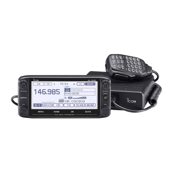
The photo shows the ID-5100E version.
Advertisement
Table of Contents

Related Manuals for Icom ID-5100A


Summary of Contents for Icom ID-5100A
- Page 1 BASIC MANUAL DUAL BAND TRANSCEIVER ID-5100A ID-5100E The photo shows the ID-5100E version. This device complies with Part 15 of the FCC Rules. Operation is subject to the following two conditions: (1) this device may not cause harmful interference, and (2) this device must accept any interference received, including interference that may cause undesired operation.
-
Page 2: Explicit Definitions
Microsoft Corporation in the United States and/or other countries. The Bluetooth word mark and logos are registered trademarks owned by Bluetooth SIG, Inc. and any use of such marks by Icom inc. is under license. Android and the Android logo are trademarks of Google, Inc. -
Page 3: Supplied Accessories
• GPS signals cannot pass through metal objects. When us- DC power Controller cable Microphone ing the ID-5100A or ID-5100E inside a vehicle, you may not cable (3.5 m:11.4 ft) (HM-207) receive GPS signals. We recommend you use it near a win- dow. -
Page 4: About The Touch Screen
ABOUT THE TOUCH SCREEN D Touch screen precautions D Touch operation Briefly touching the controller’s touch operates the function. (Short touch): If the display is touched briefly, one short • The touch screen may not properly work when LCD protec- beep sounds. - Page 5 ABOUT THE TOUCH SCREEN (Continued) Dual or Single band display selection: “kHz” tuning selection: Sets MAIN band to the right side: Tuning step selection: Dual or Single band display selection: • MAIN band: Used for TX or radio’s settings • In the Single band, touch [B] to set the B band as •...
-
Page 6: About The Supplied Cd
ABOUT THE SUPPLIED CD The following instructions and installers are included on the D Starting the CD Insert the CD into the CD drive. • Double click “Menu.exe” on the CD. • Basic Manual • Depending on the PC setting, the Menu screen shown Basic operating instructions, and are the same instructions below is automatically displayed. -
Page 7: Precautions
Immediately turn the transceiver power volume level or discontinue use. OFF and remove the power cable if it emits an abnormal odor, sound or smoke. Contact your Icom dealer or distributor R WARNING! NEVER connect the transceiver to an AC for advice. - Page 8 +80°C (+176°F) in direct sunlight, resulting in permanent dam- erating the transceiver continuously for long periods of time. age to the transceiver if left there for extended periods. Use Icom microphones only (supplied or optional). Other DO NOT place the transceiver in excessively dusty environ- manufacturer’s microphones have different pin assignments,...
-
Page 9: Table Of Contents
TABLE OF CONTENTS FOREWORD ................. i Selecting the Mode and the DR function ....15 ■ EXPLICIT DEFINITIONS ............i Transmitting ...............16 ■ IMPORTANT ................i Selecting the operating mode ........17 ■ SUPPLIED ACCESSORIES ..........ii Lock function .............17 ■ IMPORTANT NOTES ............ii Home channel function ..........18 ■... -
Page 10: Table Of Contents
TABLE OF CONTENTS (Continued) Troubleshooting ............43 Installing in a vehicle ..........81 ■ ■ Reflector operation ............45 Antenna installation ...........82 ■ ■ Updating the repeater list ..........51 Battery connection ............83 ■ ■ 5 RECORDING A QSO ONTO 9 MAINTENANCE ........85–86 AN SD CARD ........ -
Page 11: New Functions
NEW FUNCTIONS This section describes the new functions built into the ID- Add-on functions for D-PRS 5100A/E. • See the Full Manual for more details. D-PRS enables the transceiver to transmit or receive the Ob- ject, Item or Weather data in addition to position data. Two band monitoring in the DV mode With the D-PRS add-on functions, you can receive informa- tion such as an event, traffic, emergency or weather while... - Page 12 NEW FUNCTIONS Memory management Near FM Repeater search function You can easily edit the Memory or Call channel contents in You can enter FM repeater data using the DR function. The function can find only FM repeaters in your transceiver's the “MANAGE MEMORY”...
- Page 13 NEW FUNCTIONS Bluetooth ® operation Installing the optional UT-133 ® allows you to Bluetooth unit use a variety of Bluetooth ® products. • See Section 15 of the Full Manual for details. Android™ device Bluetooth ® (third party) VS-3 Calling through a reflector When you link to a reflector, you can listen to activity on all the repeaters that are connected to the reflector, and easily make contacts.
-
Page 14: Panel Description
PANEL DESCRIPTION ■ Controller — Front panel e MAIN UNIT CONNECTOR Display Connect the controller to the Main unit using the supplied control cable. (p. 79) ID-5100 r TUNING DIAL [DIAL] In the VFO mode, rotate to select the operating fre- ➥... -
Page 15: Controller - Display (Touch Screen)
PANEL DESCRIPTION ■ Controller — Display (Touch screen) Single watch mode (A band) Dualwatch mode Single watch mode (B band) In the Single watch mode: A band In the Single watch mode: B band q MAIN/SUB BAND ICON “ DTCS” is displayed while the DTCS squelch function ➥... - Page 16 PANEL DESCRIPTION Controller — Display (Touch screen) (Continued) ■ Single watch mode (A band) Dualwatch mode e r t y u i Single watch mode (B band) e MODE ICONS u EMR/BK/Packet Loss/Auto Reply ICON Displays the selected operating mode. (p. 17) “...
- Page 17 PANEL DESCRIPTION !0 SD ICON (p. 56) !8 S/RF METER (Section 2 of the Full Manual) “ ” is displayed when a SD card is inserted. Displays the relative signal strength of the receive signal. ➥ ➥ “ ” and “ ” alternately blinks while accessing the SD Displays the output power level of the transmit signal.
-
Page 18: Function Menu
PANEL DESCRIPTION Controller — Display (Touch screen) (Continued) ■ D Function menu r [SCAN] You can toggle the function group to select the desired func- Touch to open the Scan type setting window. tion keys to operate the transceiver, depending on the trans- ➥... - Page 19 PANEL DESCRIPTION !7 [CD] Touch to open the “RX HISTORY” screen. !8 [CS] !1 [DUP] Touch to open the “CALL SIGN” screen. Touch to open the duplex direction setting window. !2 [TONE] (Displayed only when in the FM/FM-N mode.) Touch to open a Tone function setting window. !9 [SCAN] !3 [REC] Touch to open the DR scan setting window.
-
Page 20: Main Unit - Front And Rear Panels
PANEL DESCRIPTION ■ Main unit — Front and rear panels y u i q SD CARD SLOT [SD CARD] y DATA JACK [DATA] Insert an SD card (purchase separately). (p. 52) Connect a PC through the optional data communication cable, for cloning or low-speed data communication in the w CONTROLLER CONNECTOR [CONTROLLER] DV mode. -
Page 21: Microphone (Hm-207)
PANEL DESCRIPTION ■ Microphone (HM-207) o DC POWER SOCKET [DC 13.8V] Connect 13.8 V DC power source through the supplied DC power cable. With the HM-207, you can input numbers for frequency or Memory channel setting, and easily adjust the audio volume Microphone connector information or squelch level. - Page 22 PANEL DESCRIPTION y [MAIN/DUAL] KEY Microphone (HM-207) (Continued) ■ In the Single watch mode, push to toggle between the ➥ A and B bands. In the Dualwatch mode, push to toggle between the ➥ MAIN and SUB bands. Hold down for 1 second to toggle between the Dual- ➥...
-
Page 23: Panel Description
PANEL DESCRIPTION !0 LED 2 D Setting frequency and Memory channel Lights green when transceiver’s power is ON. [Example for frequency setting] First, push [VFO/MR• ] to select the VFO mode. !1 [VOL∫/A] KEY Push to increase the audio output level. ➥... -
Page 24: Basic Operation
BASIC OPERATION ■ Power ON the power ■ Selecting a tuning step Hold down [ ] for 1 second to turn ON the power. Rotating [DIAL] changes the frequency in the selected tuning ➥ • A beep sounds and, after the opening message and power source steps. -
Page 25: Selecting The Watch Mode
BASIC OPERATION ■ Selecting the watch mode Dualwatch mode The transceiver has two independent watch modes: Dual- watch mode and Single watch mode. In Single watch In Single watch Dualwatch mode mode: A band mode: B band The Dualwatch mode uses the MAIN and SUB bands, and you can simultaneously monitor both bands. -
Page 26: Selecting The Operating Band
BASIC OPERATION ■ Selecting the operating band The transceiver can receive the AIR, 144 MHz or 430 MHz Touch the MHz digits. bands. • Opens the operating band setting window. The frequency range on each operating band is shown be- low. -
Page 27: Direct Frequency Input
BASIC OPERATION ■ Direct frequency input You can directly enter a frequency in the frequency entry win- Touch the numbers to enter the desired frequency. dow. • The first entered digit is displayed to the left. Then the next entered digit is displayed to the right of the previously entered digit. -
Page 28: Selecting The Mode And The Dr Function
BASIC OPERATION ■ Selecting the Mode and the DR function D VFO/Memory/Call channel/Weather channel* mode VFO mode Rotate [DIAL] to select the operating frequency or a channel. The VFO mode is used to set the operating frequency. • “ ” and the selected Memory channel number are displayed. •... -
Page 29: Transmitting
BASIC OPERATION ■ Transmitting D DR (D-STAR Repeater) function selection D Transmitting on an Amateur band The DR (D-STAR Repeater) function is for D-STAR repeater Before transmitting, monitor the operating frequency operation. In this mode, you can easily select the prepro- to make sure transmitting won’t cause interference to grammed repeaters and UR call signs by rotating [DIAL]. -
Page 30: Selecting The Operating Mode
BASIC OPERATION ■ Selecting the operating mode ■ Lock function Operating modes are determined by the modulation of the You can use the Lock function to prevent accidental frequen- radio signals. The transceiver has a total of five operating cy changes and unnecessary function access. modes, AM, AM-N, FM, FM-N and DV. -
Page 31: Home Channel Function
BASIC OPERATION ■ Home channel function ■ Speech function Home channels are often-used frequencies you can preset in When you push [ ](SPEECH), the Speech function audibly the transceiver’s VFO mode, Memory mode and DR function. announces the displayed frequency and operating mode in Select the Home channel function by just touching [HOME] the VFO, Memory or Call channel modes, or the call sign of in each mode. -
Page 32: Memory Management
MEMORY MANAGEMENT ■ Writing Memory channels ■ Checking the Memory contents The Memory mode is useful to quickly select often-used re- The contents of the Memory channels can be checked on the peaters. “MEMORY LIST” screen. In this section, the basic channel programming is described. See the Full Manual for details. -
Page 33: Memory Operation
MEMORY OPERATION Touch [ ∫] or [√]. • Displays Channel 5. Touch “005.” • Displays the data in Channel 5. • Touch [∫] or [√] one or more times to select the page. Touch [MENU]. • Closes the “MEMORY CH ALL” screen. -
Page 34: Star Operation
ID-5100A/E 1200 MHz (144/430 MHz) You can communicate with a 1200 MHz D-STAR station using the ID-5100A/E! Easy call sign entry with the ● Repeater list or TX/RX History Easy Destination (TO) setting! Call Sign Capture key ●... -
Page 35: D-Star Introduction
D-STAR OPERATION Before starting D-STAR, the following steps are needed. STEP 1 STEP 2 Entering your call sign (MY) into the transceiver. Registering your call sign (MY) to a gateway repeater. STEP 3 Entering your D-STAR equipment into your registration form. You have IMPORTANT! completed the steps!! -
Page 36: Ways To Communicate With The Dr Function
D-STAR OPERATION ■ Ways to Communicate with the DR function With the DR function, the transceiver has three ways to communicate, as shown below. Access repeater Simplex call Local area call Hamacho repeater Hamacho area To call another station not using a repeater. To call through your local area (access) repeater. -
Page 37: Enter Your Call Sign Into The Transceiver
D-STAR OPERATION ■ Enter your call sign into the transceiver You can enter up to six MY call signs, in [MY1] through [MY6]. Enter the call sign Example: Enter “JA3YUA” as your own call sign into the MY Touch the desired keypad to select the first digit. call sign memory [MY1]. - Page 38 D-STAR OPERATION Enter your call sign into the transceiver (Continued) ■ Keys used for entry Save the call sign Moves the cursor Touch [ENT]. • Saves the entered call sign and returns to the “MY CALL SIGN” screen. Deletes • See “Convenient” below if you want to enter a note. Sets Cancels Enters a space...
- Page 39 D-STAR OPERATION Convenient! ✓ If desired, enter a note of up to 4 characters, such as the model of the transceiver, name, area name, and so on, after your call sign. Touch [ ] one or more times until the cursor moves to the right of the “/”.
-
Page 40: Register Your Call Sign At A Gateway Repeater
D-STAR OPERATION ■ Register your call sign at a gateway repeater To use the Internet, you must register your call sign with a Access the call sign registration screen repeater that has a gateway, usually one near your home lo- Access the following URL to find the gateway repeater cation. - Page 41 D-STAR OPERATION Register your call sign Register your D-Star equipment Follow the registration instructions found there. Register your D-STAR equipment information. When you receive a notification from the administrator, Ask the gateway repeater administrator for details. your call sign registration has been approved. When your registration is complete, log out of your per- sonal account, and start using the D-STAR network.
-
Page 42: Making A Simplex Call
D-STAR OPERATION ■ Making a Simplex call You can make a transceiver to transceiver call (through no Touch “Repeater List.” repeater) in the DR screen. • Opens the “REPEATER GROUP” screen. NOTE: Depending on the transceiver's version, the fre- quencies may be different. Check for acceptable frequen- cies for your operating area. - Page 43 D-STAR OPERATION Hold down [PTT] to transmit • The LED1 on the microphone lights red. For your reference: The simplex frequencies can be changed in the MENU screen. ( DV memory > Repeater List > Repeater group > Simplex) When you make a simplex call in the VFO mode, the LCD changes, as shown below.
-
Page 44: Accessing Repeaters
D-STAR OPERATION ■ Accessing repeaters This section describes how to check whether or not you can Touch the repeater group where your access repeater is access your local area repeater (Access repeater), and if your listed. (Example: “11: Japan”) signal is successfully sent to a destination repeater. If your call sign (MY) has not been set, or your call sign and equipment have not been registered at a D-STAR re- peater, see pages 24 to 28. - Page 45 D-STAR OPERATION Select the Destination repeater (“TO”) Check whether you can access the repeater Touch the “TO” field. !2 Hold down [PTT] for approximately 1 second to access the • Check whether “TO” is selected. repeater. Touch the “TO” field again. •...
-
Page 46: Using The Rx History
D-STAR OPERATION ■ Using the RX history When a DV call is received, the call signs of the caller, the To display a received call sign called station and the called station’s access repeater are Touch the Function group icon one or more times. stored in the RX history file. - Page 47 D-STAR OPERATION Save the destination call sign into your call sign mem- Touch “NAME.” ory from RX History • Opens the “NAME” screen. • Enter a name of up to 16 characters, including spaces. Touch [ ∫] or [√] one or more times to select the RX HIS- (Example: TOM) TORY record with the call sign that you want to save to memory.
-
Page 48: Capturing A Call Sign
D-STAR OPERATION ■ Capturing a call sign After you receive a repeater’s signal, the calling station’s call Set the received call sign to the destination sign can be captured by touching the Call Sign Capture key Touch the Function group icon one or more times. ([RX>CS]) for 1 second. - Page 49 D-STAR OPERATION NOTE: • After touching [RX>CS], you can select another call sign in the RX history. • When a received signal is weak or DR scanning, the call sign may not be correctly received. In that case, you can- not capture a call sign.
-
Page 50: Making A Local Area Call
D-STAR OPERATION ■ Making a Local area call A Local area call can be made when “Local CQ” is used to set Touch the repeater group where your access repeater is “CQCQCQ” in “TO” (Destination). listed. (Example: “11: Japan”) What is a Local Area Call?? ✓... - Page 51 D-STAR OPERATION Set “TO” (Destination) Hold down [PTT] to transmit Touch the “TO” field. • The LED1 on the microphone lights red. • Check whether “TO” is selected. Touch the “TO” field again. • Opens the “TO SELECT” screen. Touch “Local CQ.” •...
-
Page 52: Making A Gateway Repeater Call
D-STAR OPERATION ■ Making a Gateway Repeater call A Gateway call can be made when a destination repeater is Touch the repeater group where your access repeater is selected in “TO” (Destination). listed. (Example: “11: Japan”) What is a Gateway Repeater Call?? ✓... - Page 53 D-STAR OPERATION Set “TO” (Destination) !1 Touch your destination repeater. (Example: “Hamacho”) Touch the “TO” field. • Returns to the DR screen, and the selected repeater name is • Check whether “TO” is selected. displayed in “TO.” Touch the “TO” field again. •...
-
Page 54: Calling An Individual Station
D-STAR OPERATION ■ Calling an individual station You can make a call to an individual station when the station Touch the repeater group where your access repeater is call sign is selected in “TO” (Destination). listed. (Example: “11: Japan”) When you call an individual station call sign through a gate- way, your call is automatically sent to the last repeater that the station accessed. - Page 55 D-STAR OPERATION Set “TO” (Destination) Hold down [PTT] to transmit Touch the “TO” field. • The LED1 on the microphone lights red. • Check whether “TO” is selected. Touch the “TO” field again. • Opens the “TO SELECT” screen. Touch “Your Call Sign.” •...
-
Page 56: Troubleshooting
D-STAR OPERATION ■ Troubleshooting To communicate through the repeater, your signal must access to the repeater. When your signal accesses your local repeater, but it is not sent to the destination repeater, the repeater replies with an status message. PROBLEM POSSIBLE CAUSE SOLUTION REF. - Page 57 D-STAR OPERATION PROBLEM POSSIBLE CAUSE SOLUTION REF. After your call, the repeater re- • The repeater cannot connect to the destina- • Check the repeater setting. — plies ‘RPT?’ and call sign of the tion repeater. destination repeater. • The repeater is busy. •...
-
Page 58: Reflector Operation
D-STAR OPERATION ■ Reflector operation D What is the reflector? D Linking to a reflector A reflector is a special server connected to the internet and If your repeater is not currently linked to a reflector, or you running a version of dplus software. If the dplus software is want to change to another reflector, you can do so following installed on your access repeater, it provides various functions the steps below. - Page 59 D-STAR OPERATION Touch “Link to Reflector.” Using the TX History Touch “Direct Input.” The TX History stores the up to 5 reflectors that your access Touch [+] or [–] one or more times to select the reflector repeater linked before. number.
-
Page 60: Using A Reflector
D-STAR OPERATION Reflector operation ■ D Using a reflector Linking to a reflector (Continued) Touch [DR]. Touch “Link to Reflector.” Check whether or not “TO” is selected. • If “TO” is not selected, touch the “TO” field. Touch the “TO” field. •... -
Page 61: Unlinking A Reflector
D-STAR OPERATION D Unlinking a reflector Touch “Unlink Reflector.” Before linking to another reflector, be sure to unlink the cur- • The transceiver returns to the DR screen. rent reflector. • “Unlink Reflector” and “U” are displayed in “TO.” Touch [DR]. Check whether or not “TO”... - Page 62 D-STAR OPERATION Reflector operation (Continued) ■ D Reflector Echo Testing Touch “Echo Test.” You can transmit a short message, and after releasing [PTT], • The transceiver returns to the DR screen. your message will be played back. It is a useful check of how •...
-
Page 63: Requesting Repeater Information
D-STAR OPERATION D Requesting repeater information When you send the repeater information command, an ID Touch [ √] to select the next page. message is sent back. Touch “Repeater Information.” • The transceiver returns to the DR screen. • “Repeater Information” and “I” are displayed in “TO.” Touch [DR]. -
Page 64: Updating The Repeater List
File Name: 5100_USA_140401.zip (Example) Depending on the ID-5100A updated file date. Cloning software(Rev. MM) and manuals 20MM/MM/MM ID-5100E Depending on the version. w Unzip the ZIP file that you downloaded from the Icom web- site. The “5100_USA_140401” (Example) folder will be cre- ated. - Page 65 Inserting the SD card into a PC e Insert the SD card into the SD card drive on your PC. • Icom recommends that you format all SD cards to be used with the transceiver, even preformatted SD cards for PCs or other uses.
- Page 66 Touch the CSV file to be loaded. (Example: “5100_USA_Rpt_140401.csv”) • The “Keep 'SKIP' settings in Repeater List?” window appears. SD card from the external card reader Icom recommends that you save the current data before loading other data into the transceiver.
-
Page 67: D-Star Operation
D-STAR OPERATION !0 Touch [YES] or [NO]. For your reference: • When you touch [YES], the skip settings of the repeater list are If you copy the ICF file to [Setting] of the SD card, the re- retained. peater list can be updated with the same procedures. In this •... -
Page 68: Recording A Qso Onto An Sd Card
SDHC card are simply called SD cards. • When reading or writing data is impossible, the SD card’s • Icom recommends that you format all SD cards to be used lifetime has ended. In this case, purchase a new one. We... -
Page 69: Inserting The Sd Card
RECORDING A QSO ONTO AN SD CARD ■ Inserting the SD card D Formatting the SD card • If you use a brand new SD card, format it by doing the following steps. D Inserting the SD card • Formatting a card erases all its data. Before formatting Turn OFF the transceiver. -
Page 70: Recording A Qso Audio
RECORDING A QSO ONTO AN SD CARD ■ Recording a QSO audio Touch the Function group icon one or more times. Touch the record icon. • When the DR screen is displayed, selects the D-3 menu. • The “Stop recording?” dialog box appears. •... -
Page 71: Playing Recorded Audio
RECORDING A QSO ONTO AN SD CARD ■ Playing recorded audio ■ Removing the SD card Touch [MENU]. D Removing the SD card Touch “Play Files.” Turn OFF the power. (Voice Memo > QSO Recorder > Play Files) Push in the SD card until a •... -
Page 72: Gps Operation
GPS OPERATION ■ GPS operation ■ Checking your GPS position The transceiver has a built-in GPS receiver. You can You can check your current position. If you transmit while displaying the GPS position screen, the check your current position, and transmit GPS data in screen closes. - Page 73 CALLING A DESTINATION STATION D About the GPS Position screen Touch [ ∫] or [√] one or more times. • Selects the page. My position Compass Latitude screen (MY) direction top is North. Longitude Your course heading is Grid locator East.
-
Page 74: Menu Screen
MENU SCREEN ■ Menu item selection The Menu screen is used to program infrequently changed Touch “Auto Power OFF.” values or function settings. • To set other item, touch [] to go back a tree level. In addition to this page, see pages 62 through 78 for details of each item’s options and their default value. -
Page 75: Menu Items And Default Settings
MENU SCREEN ■ Menu items and Default settings NOTE: The default settings shown in bold letters below are for the USA version. The default settings may differ, depending on your transceiver version. DUP/TONE... Settings to access repeaters. Offset Freq 0.000~0.600.00* ~59.995 MHz Sets the frequency offset for duplex (repeater) op- eration. - Page 76 MENU SCREEN Menu items and Default settings (Continued) ■ Scan Set scan options. Pause Timer 2sec~10sec~20sec or HOLD Selects the scan pause time. When receiving signals, the scan pauses according to the scan pause timer. Resume Timer 0sec~2sec~5sec or HOLD Selects the scan resume time from a pause after the received signal disappears.
- Page 77 MENU SCREEN PTT Auto REC OFF or ON Turns the PTT Automatic Recording function ON or OFF. Player Set Skip Time 3sec, 5sec, 10sec or 30sec Sets the Skip time to rewind or forward the recorded audio when you push the fast-rewind or fast-forward key during playback.
- Page 78 MENU SCREEN Menu items and Default settings (Continued) ■ TX Format Position 1:Car, 2:Van, 3:Truck or 4:House QTH (VHF) Selects a desired D-PRS Symbol to transmit. Symbol SSID - - -, (-0), -1~-15 or -A~-Z Selects the APRS ® call sign SSID. Comment Enters a comment to transmit.
- Page 79 MENU SCREEN Power 0W, 1W, 4W, 9W, 16W, 25W, 36W, Selects a object station’s TX power level to transmit. 49W, 64W or 81W 10ft, 20ft, 40ft, 80ft, 160ft, 320ft, Height Selects the height of the object station to transmit. 640ft, 1280ft, 2560ft, 5120ft* Gain 0dB~9dB Selects the antenna gain of the object station to...
- Page 80 MENU SCREEN Menu items and Default settings (Continued) ■ Omni, 45°NE, 90°E, 135°SE, 180°S, Directivity Selects the antenna directivity of the item station to 225°SW, 270°W, 315°NW, 360°N transmit. SSID - - -, (-0), -1~-15 or -A~-Z Selects the APRS ®...
- Page 81 MENU SCREEN GPS Auto TX OFF, 5sec, 10sec, 30sec, 1min, Selects a time option for the GPS automatic trans- 3min, 5min, 10min or 30min mission function. Call Sign Set and display the DV mode call signs. UR: CQCQCQ, R1: --------, Displays the operating call signs.
- Page 82 MENU SCREEN Menu items and Default settings (Continued) ■ Cut, Normal or Boost RX Treble Sets the DV mode received audio treble filter level to Cut, Normal or Boost. RX Bass Boost OFF or ON Turns the DV mode received audio Bass Boost func- tion ON or OFF Cut, Normal or Boost TX Bass...
- Page 83 MENU SCREEN OFF or ON Turns the EMR (Enhanced Monitor Request) com- munication mode ON or OFF. After turning OFF the transceiver, the EMR mode will be cancelled. EMR AF Level 0~19~32 Sets the audio output level when an EMR mode sig- nal is received.
- Page 84 MENU SCREEN Menu items and Default settings (Continued) ■ OFF or ON RX History Log Selects to make a DV mode's receive history log on the SD card, or not. CSV Format Separator/Decimal Sep [,] Dec [.] , Sep [;] Dec [.] or Selects the separator and the decimal character for Sep [;] Dec [,] the CSV format.
- Page 85 MENU SCREEN During RX/Standby [UP]:UP [DN]:DOWN Selects the key function to be used while receiving or in the standby mode. During TX [UP]:--- [DN]:--- Selects the key function to be used while transmit- ting. One-Touch PTT(Remote MIC) OFF or ON Turns the One-Touch PTT function ON or OFF.
- Page 86 MENU SCREEN Menu items and Default settings (Continued) ■ Heterodyne Normal or Reverse Heterodyne (A BAND VHF) Effective to eliminate internal spurious that may oc- cur in a rare combination of dual band frequencies, when operating VHF on the A band. Normal or Reverse Heterodyne (A BAND UHF) Effective to eliminate internal spurious that may oc-...
- Page 87 MENU SCREEN RX Position Display OFF, ON (Main/Sub) or Selects whether or not to display the caller’s posi- ON (Main Only) tion data in a dialog when the data is included in the signal received in the DV mode. RX Position Display Timer 5sec, 10sec, 15sec, 30sec, Hold Sets the RX position data display time period.
- Page 88 MENU SCREEN Menu items and Default settings (Continued) ■ English or Japanese System Language Selects English or Japanese as the system language of the transceiver. Sounds Sets the Sound options. Beep Level Sets the beep output level. Key-Touch Beep OFF or ON Turns the confirmation beep tones when key is pushed, ON or OFF.
- Page 89 MENU SCREEN SD Card* Sets the SD card options. Load Setting File selection ALL, Except My Station, Loads the settings file to the transceiver. Repeater List Only Save Setting <<New File>> Saves the settings as a new file. File selection Saves the settings in a selected file.
- Page 90 Sets the VOX Time-Out Timer to prevent an acciden- 10min or 15min tal prolonged transmission. ® Icom Headset Sets to use the optional Icom Bluetooth headset (VS-3). Power Save OFF or ON Sets the Power save function to prolong the headset battery.
-
Page 91: Menu Screen
MENU SCREEN PTT Beep OFF or ON Sets to sound a beep when you push [PTT]. Custom Key Beep OFF or ON Sets to sound a beep when you push the custom key ([PLAY]/[FWD]/[RWD]). Custom Key [PLAY]:---, [FWD]:UP, Selects the key function of the custom key ([PLAY]/ [RWD]: DOWN [FWD]/[RWD]). -
Page 92: Installation And Connections
INSTALLATION AND CONNECTIONS ■ Connect controller to main unit ■ DC power supply connection Connect the controller to the main unit with the supplied con- Use a 13.8 V DC power supply with at least 20 A capacity. trol cable. Connect the black DC power cable to the (–) Negative termi- •... -
Page 93: Controller Installation
INSTALLATION AND CONNECTIONS ■ Controller installation D When installing into your vehicle You can install the controller on the dashboard or the console Slide the MBA-2 ’s guide down over the MBF-1’s locking of your vehicle with optional MBA-2 head, as shown below. controller bracket •... -
Page 94: Installing In A Vehicle
INSTALLATION AND CONNECTIONS ■ Installing in a vehicle Controller installation (Continued) ■ D When installing to a flat surface You can install the controller on a flat surface with the optional CAUTION: NEVER place the main unit or remote controller MBA-2 controller bracket where normal operation of the vehicle may be hindered or... -
Page 95: Antenna Installation
INSTALLATION AND CONNECTIONS ■ Antenna installation Using the mounting bracket • Antenna location You can install the main unit on the dashboard or the console of your vehicle with the optional MBF-4 mobile bracket Drill 4 holes where the mounting bracket is to be installed. •... -
Page 96: Battery Connection
INSTALLATION AND CONNECTIONS ■ Battery connection Antenna installation (Continued) ■ D About Coaxial cable For radio communications, the antenna is of critically impor- RWARNING! tance, along with output power and receiver sensitivity. • NEVER remove the fuses from the cable connecting the Select a well-matched 50 ˘... - Page 97 INSTALLATION AND CONNECTIONS CONNECTING A VEHICLE BATTERY RWARNING! (About DC power supply) • Make sure DC power cable polarity is correct. Red: Positive + terminal Black: Negative – terminal • DO NOT pull or bend the DC power cable. Grommet NOTE: Use terminals for the cable connections.
-
Page 98: Maintenance
MAINTENANCE ■ Resetting Occasionally, erroneous information will be displayed when, Touch “Partial Reset.” for example, first applying power. This may be caused exter- nally by static electricity or by other factors. If this problem occurs, turn OFF power. After waiting a few seconds, turn ON power again. If the prob- lem is still there, perform a Partial reset or an All reset. -
Page 99: Power Protect Function
NOTE: When the power supply voltage is over 17.0 V, the transceiver automatically displays “Over Voltage,” and then sounds a warning beep. In this case, the transceiver may be damaged, and contact your nearest Icom Dealer or R WARNING! NEVER remove the fuse holders from the Service Center. -
Page 100: Information
Latvia • Consult the dealer or an experienced radio/TV technician for help. CAUTION: Changes or modifications to this device, not ex- pressly approved by Icom Inc., could void your authority to operate this device under FCC regulations. -
Page 101: Index
INDEX Connection Access repeater Connect controller to main unit ........79 Accessing repeaters ............31 Controller Antenna Display (Touch screen) .............2 Antenna installation ............82 Front panel ...............1 Accessories ................ii Country code list ..............87 Audio volume setting ............11 DC power supply connection ..........79 Band D-STAR operation ...............21 Operating band selection ..........13... - Page 102 INDEX MAIN or SUB band selection ..........12 Operation ...............59 Menu screen GPS receive setting ............59 Entering ................61 GPS Position screen ............60 Memory channel Checking your GPS position ..........59 Memory mode ..............15 Displaying Position Data ..........59 Memory management ............19 Checking the Memory contents ........19 Setting a Memory channel ..........10 Home channel Writing Memory channels ..........19...
-
Page 103: Index
INDEX Recording a QSO audio .............57 Table of contents ..............viii Reflector Touch screen Echo Testing ..............49 Maintenance ..............iii Linking to a reflector ............45 Operation ................ iii Operation ...............45 Precautions ..............iii Requesting repeater information ........50 Touch Area ..............iii Unlinking a reflector ............48 Transmitting ................16 Using a reflector .............47... - Page 104 MEMO...
- Page 105 MEMO...
- Page 106 MEMO...
- Page 107 MEMO...
- Page 108 ■ ■ ■ ■ ■ ■ ■ ■ ■ ■ ■ ■ ■ ■ ■ ■ ■ ■ ■ A-7115D-2EX-q Printed in Japan 2014 Icom Inc. © 1-1-32 Kamiminami, Hirano-ku, Osaka 547-0003, Japan Printed on recycled paper with soy ink.