Icom ID-5100A Full Manual
Dual band transceiver
Hide thumbs
Also See for ID-5100A:
- Basic manual (108 pages) ,
- Brochure & specs (4 pages) ,
- Operating manual (2 pages)
Table of Contents
Advertisement
Quick Links
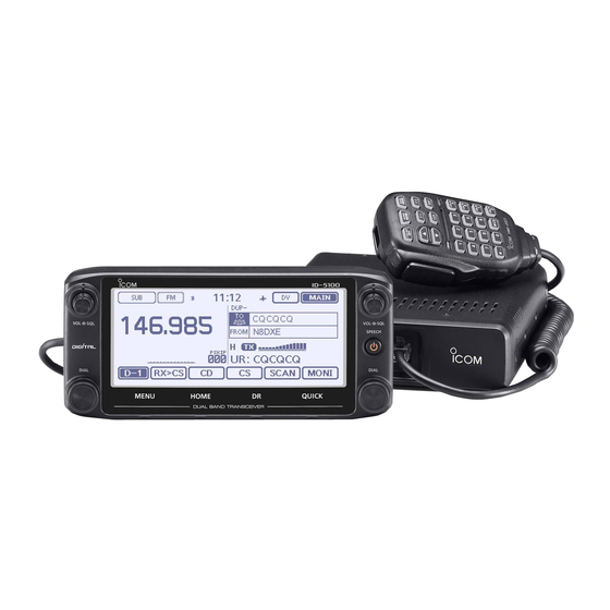
DUAL BAND TRANSCEIVER
ID-5100A
ID-5100E
FULL MANUAL
To update the repeater list,
click here!
INTRODUCTION
1
PANEL DESCRIPTION
2
BASIC OPERATION
3
MEMORY OPERATION
4
SCAN OPERATION
5
PRIORITY WATCH
6
D-STAR OPERATION <BASIC>
7
D-STAR OPERATION <ADVANCED>
8
GPS OPERATION
9
USING AN SD CARD
10 VOICE MEMORY
11 REPEATER AND DUPLEX OPERATIONS
12 MENU SCREEN
13 OTHER FUNCTIONS
14 OPTIONS
®
15 Bluetooth
OPERATION
16 SPECIFICATIONS
17 MAINTENANCE
INDEX
Advertisement
Chapters
Table of Contents
Troubleshooting

Related Manuals for Icom ID-5100A


Summary of Contents for Icom ID-5100A
- Page 1 FULL MANUAL INTRODUCTION PANEL DESCRIPTION BASIC OPERATION MEMORY OPERATION SCAN OPERATION DUAL BAND TRANSCEIVER PRIORITY WATCH ID-5100A D-STAR OPERATION <BASIC> ID-5100E D-STAR OPERATION <ADVANCED> GPS OPERATION USING AN SD CARD 10 VOICE MEMORY 11 REPEATER AND DUPLEX OPERATIONS 12 MENU SCREEN...
-
Page 2: Supplied Accessories
With proper care, this product should provide you with years of trouble-free operation. We thank you for making your ID-5100A or ID-5100E your transceiver of choice, and hope you agree with Icom’s philosophy of “technology first.” Many hours or research and development went into the design of your ID-5100A or ID-5100E. -
Page 3: About The Supplied Cd
Previous view INTRODUCTION ABOUT THE SUPPLIED CD Starting the CD The following instructions and installers are included on the CD. Insert the CD into the CD drive. • Double click “Menu.exe” on the CD. • Basic Manual • Depending on the PC setting, the Menu screen shown Basic operating instructions below is automatically displayed. - Page 4 Previous view INTRODUCTION ABOUT THE TOUCH SCREEN Touch screen precautions Touch operation Briefly touching the controller’s touch operates the (Short touch): If the display is touched briefly, one function. short beep sounds. • The touch screen may not properly work when LCD (Long touch): If the display is touched for 1 sec- protection film or sheet is attached.
- Page 5 Previous view INTRODUCTION ® ® Functions and features of Adobe Reader ® ® The following functions and features can be used with Adobe Reader • Keyword search Click “Find (Ctrl+F)” or “Advanced • Find screen Search (Shift+Ctrl+F)” in the Edit menu to open the search screen.
- Page 6 [SQL], or operating a key, touch screen or micro- phone. Icom, Icom Inc. and the Icom logo are registered trademarks of Icom Incorporated (Japan) in Japan, the United States, the United Kingdom, Germany, France, Spain, Russia and/or other countries. Adobe and Adobe Reader are registered trademark of Adobe Systems Incorporated.
-
Page 7: Table Of Contents
Previous view Section PANEL DESCRIPTION Controller — Front panel ............1-2 Controller — Display (Touch screen)........1-3 Function menu .................1-5 Main unit — Front and rear panels ........1-7 Microphone connector information ..........1-7 Microphone (HM-207) ..............1-8 Setting frequency and Memory channel ........1-9... -
Page 8: Section 1 Panel Description
Previous view PANEL DESCRIPTION Controller — Front panel Display About control’s operation In the Dualwatch mode, the left side controls are ID-5100 used for the left side band, and the right side controls are used for the right side. In the Single watch mode, the left side controls are used for the A band, and the right side controls are used for the B band. -
Page 9: Controller - Display (Touch Screen)
Previous view PANEL DESCRIPTION Controller — Display (Touch screen) Dualwatch mode Single watch mode (A band) w e r t y u i Single watch mode (B band) This side becomes the A band This side becomes the B band in the Single watch mode in the Single watch mode q MAIN/SUB BAND ICON (p. - Page 10 Previous view PANEL DESCRIPTION Controller — Display (Touch screen) (Continued) Dualwatch mode Single watch mode (A band) Single watch mode (B band) This side becomes the A band This side becomes the B band in the Single watch mode in the Single watch mode !3 DR SCREEN !9 FUNCTION MENU DISPLAY (p.
-
Page 11: D Function Menu
Previous view PANEL DESCRIPTION Controller — Display (Touch screen) (Continued) Function menu You can toggle the function group to select the desired func- tion keys to operate the transceiver, depending on the trans- !1 [DUP] ceiver’s operating mode or status. Touch to open the duplex direction setting window. - Page 12 Previous view PANEL DESCRIPTION Controller — Display (Touch screen) Function menu (Continued) @1 [SKIP] Touch to open the skip setting window for the Ac- ➥ cess repeater scan. Touch for 1 second to set the skip setting in the ➥ Function menu.
-
Page 13: Main Unit - Front And Rear Panels
The cooling fan for heat dissipation. transceiver. You can select the Fan control option in the Menu • Use for the transceive function with another Icom screen; automatically starts to rotate when you be- CI-V transceiver or receiver. When the transceive... -
Page 14: Microphone (Hm-207)
Previous view PANEL DESCRIPTION Microphone (HM-207) With the HM-207, you can enter numbers for frequency or Memory channel setting, and easily adjust the audio volume or squelch level. Mic element q LED 1 i [CLR] KEY Lights red while transmitting with [PTT]. In the Menu screen or Quick Menu window, push to return to the standby screen. -
Page 15: D Setting Frequency And Memory Channel
Previous view PANEL DESCRIPTION Microphone (HM-207) (Continued) D Setting frequency and Memory channel [Example for frequency setting] First, push [VFO/MR• ] to select the VFO mode. To enter the 435.680 MHz frequency: Push [4], [3], [5], [6], [8], [0], then [ENT]. ➥... - Page 16 Previous view Section BASIC OPERATION Power ON and setting audio volume/squelch level....2-2 Turning ON the power .............2-2 Setting audio volume and squelch level ........2-2 Selecting the watch mode ............2-3 Selecting the MAIN or SUB band ..........2-3 Selecting the A or B bands ............2-3 Selecting the operating band ..........2-4 Operating band setting...
-
Page 17: Section 2 Basic Operation
Previous view BASIC OPERATION Power ON and setting audio volume/squelch level Turning ON the power (Sample) Hold down [ ] for 1 second to turn ON the power. ➥ • A beep sounds and, after the opening message and pow- er source voltage are displayed, the operating frequency appears. -
Page 18: Selecting The Watch Mode
Previous view BASIC OPERATION Selecting the watch mode The transceiver has two independent watch modes; Dualwatch mode and Single watch mode. Dualwatch mode Dualwatch mode The Dualwatch mode uses the MAIN and SUB bands, and you can simultaneously monitor both bands. In the Dualwatch mode, both MAIN and SUB bands are displayed side by side. -
Page 19: Selecting The Operating Band
Previous view BASIC OPERATION Selecting the operating band The transceiver can receive the AIR, 144 MHz or 430 Operating band Frequency range MHz bands. 118.000 MHz to 136.99166 MHz The frequency range on each operating band is shown 144 MHz 137.000 MHz to 174.000 MHz to the right. -
Page 20: Direct Frequency Entry
Previous view BASIC OPERATION Direct frequency entry You can directly enter a frequency in the frequency en- Touch the numbers to enter the desired frequency. • The first entered digit is displayed to the left. Then the window next entered digit is displayed to the right of the previ- ously entered digit. -
Page 21: Selecting A Tuning Step
Previous view BASIC OPERATION Selecting a tuning step Tuning step selection Rotating [DIAL] changes the frequency in the selected tuning steps. Touch the kHz digits for 1 second. The VFO scan uses this step to search for a signal. • Opens the Tuning step setting window. Tuning steps (kHz) 6.25 8.33*... -
Page 22: Quick Tuning Function
Previous view BASIC OPERATION Quick Tuning function Selecting a Squelch delay You can change the operating frequency in ‘MHz’ steps You can select a squelch delay in the Menu screen to for quick tuning. prevent repeated opening and closing of the squelch while receiving the same signal. -
Page 23: Selecting The Operating Mode
Previous view BASIC OPERATION Selecting the operating mode Monitor function Operating modes are determined by the modulation of You can use this function to listen to weak signals with- the radio signals. The transceiver has a total of five op- out disturbing the squelch setting, or having to manu- erating modes;... -
Page 24: Selecting The Mode And The Dr Function
Previous view BASIC OPERATION Selecting the Mode and the DR function D VFO/Memory/Call channel/Weather channel* mode VFO mode Touch the Memory channel number. • Opens the Mode setting window. The VFO mode is used to set the operating frequency. Memory mode The Memory mode is used to operate on Memory channels. -
Page 25: Ddr (D-Star Repeater) Function Selection
Previous view BASIC OPERATION Selecting the Mode and the DR function (Continued) D DR (D-STAR Repeater) function selection The DR (D-STAR Repeater) function is for D-STAR re- peater operation. In this mode, you can easily select the preprogrammed repeaters and UR call signs by ro- tating [DIAL]. -
Page 26: Receiving
Previous view BASIC OPERATION Receiving Example: Receiving on 146.010 MHz Touch the Memory channel number. • Opens the Mode setting window. Touch [VFO]. • Selects the VFO mode. Touch the MHz digits. • Opens the operating band setting window. Touch [144]. Touch the Mode icon. -
Page 27: Transmitting
Previous view BASIC OPERATION Transmitting D Transmitting on an Amateur band NOTE: Before transmitting, monitor the operating fre- • If the MAIN band frequency is a multiple of the SUB quency to make sure transmitting won’t cause band frequency, you might receive a very small interference to other stations on the same fre- signal on the SUB band when you transmit. -
Page 28: Lock Function
Previous view BASIC OPERATION Lock function Attenuator function You can use the Lock function to prevent accidental fre- The transceiver has an RF attenuator related to the quency changes and unnecessary function access. squelch control setting. You can add up to approximate- ly 20 dB of attenuation at it’s maximum setting. -
Page 29: Band Scope Function
Previous view BASIC OPERATION Band Scope function D Sweep operation Use the Band Scope function to visually search a spec- ified frequency range around the displayed frequency. Example: Continuous sweeps centered on 146.010 MHz You can use this function to search for a signal, and see Rotate [DIAL] to set 146.010 MHz. -
Page 30: Dualwatch Operation
Previous view BASIC OPERATION Dualwatch operation Microphone gain level setting Dualwatch operation simultaneously monitors frequen- Set the microphone gain level in the Menu screen. cies in the MAIN and SUB bands. In the Dualwatch mode, the audio output may be inter- Touch [MENU]. -
Page 31: Home Channel Function
Previous view BASIC OPERATION Home channel function Home channels are often-used frequencies you can preset in the transceiver’s VFO mode, Memory mode and DR function. Select the Home channel function by just touching [HOME] in each mode. D Home channel setting D Home channel operation Select the desired mode or the DR screen to set the Select the desired mode or the DR screen in which... -
Page 32: Speech Function
Previous view BASIC OPERATION Speech function Example: When “Hamacho” (JP1YIU A) is selected in When you push [ ](SPEECH), the Speech function au- “FROM,” push [ ](SPEECH). dibly announces the displayed frequency and operating mode in the VFO, Memory or Call channel modes, or the call sign of the DR function. - Page 33 Previous view Section MEMORY OPERATION General description...............3-2 The number of the Memory channel ........3-2 Memory channel content ............3-2 Manage Memory screen description ........3-3 Tree view of the Manage Memory screen ......3-3 Entering the Manage Memory screen ........3-3 Selecting a Memory channel ..........3-4 Selecting a Call channel ............3-5 Writing into a Memory channel ...........3-6 Writing into the selected channel...
-
Page 34: Section 3 Memory Operation
Therefore, we recommend that you backup the memory content or save it to an SD card or to a PC. • The SD card is not available from Icom. Purchase an SD card to meet your needs. • The CS-5100... -
Page 35: Manage Memory Screen Description
Previous view MEMORY OPERATION Manage Memory screen description D Entering the Manage Memory screen The “MANAGE MEMORY” screen enables you to eas- ily edit the Memory or Call channel content. Touch [MENU]. Touch “Manage Memory.” • View the Memory or Call channel content on a list. •... -
Page 36: Selecting A Memory Channel
Previous view MEMORY OPERATION Selecting a Memory channel Touch the Memory channel number. • Opens the Mode setting window. Touch [MR]. • Selects the Memory mode. • Displays “ ” and the selected Memory channel num- ber. Appears Rotate [DIAL] to select a Memory channel. •... -
Page 37: Selecting A Call Channel
Previous view MEMORY OPERATION Selecting a Call channel Two Call channels (C0/C1) are selectable in each of the 144 and 430 MHz bands. Factory default frequencies and operating modes are entered into the Call channels. Change these to suit your operating needs. Touch the Memory channel number. -
Page 38: Writing Into A Memory Channel
Previous view MEMORY OPERATION Writing into a Memory channel After setting a frequency in the VFO mode, you can write it into a Memory channel. When writing into a channel, you can select the des- tination channel between your desired channel or the lowest blank channel. -
Page 39: D Overwriting Into The Selected Channel
Previous view MEMORY OPERATION Writing into a Memory channel (Continued) D Overwriting into the selected channel You can write a frequency into a pre-entered channel. Example: Writing 147.010 MHz into Memory channel Touch the Memory channel number. !0 Touch [YES]. •... -
Page 40: D Copying Memory Content To The Vfo
Previous view MEMORY OPERATION Writing into a Memory channel (Continued) D Copying Memory content to the VFO It is convenient when you want to operate on the fre- quency around the Memory or Call channel. Touch the Memory channel number. Touch [YES]. -
Page 41: D Copying Memory Content To Another Memory
Previous view MEMORY OPERATION Writing into a Memory channel (Continued) D Copying Memory content to another Memory channel You can copy the memory content to another Memory channel. Touch “Copy.” Touch the Function group icon one or more times. • “DESTINATION” blinks at the top left of the screen. •... -
Page 42: Memory Bank Setting
Previous view MEMORY OPERATION Memory bank setting The transceiver has a total of 26 banks (A to Z). NOTE: The memory banks are only used to hold Regular memory channels 0 to 999 are assignable to memory channels. Thus if the original memory chan- any desired bank for easy memory management. -
Page 43: D Directly Entering Into A Memory Bank
Previous view MEMORY OPERATION Memory bank setting (Continued) D Directly entering into a memory bank You can also enter the memory content directly into a memory bank channel. This way is a short cut to creat- ing a memory channel, and then assigning it to a bank. In that case, the transceiver automatically selects the lowest blank memory channel, to program. -
Page 44: D Selecting The Memory Bank Mode
Previous view MEMORY OPERATION Memory bank setting (Continued) D Selecting the Memory bank mode When you select the Memory bank mode, rotating [DIAL] selects only the entered bank channels in the selected bank. Touch the Memory channel number. • Opens the Mode setting window. Touch [MR]. -
Page 45: Entering A Memory Or Bank Name
Previous view MEMORY OPERATION Entering a Memory or Bank name You can enter an alphanumeric name for each Memory, including Call channels, and Banks. Names can be a maximum of 16 characters. D Entering a Memory name Touch the Function group icon one or more times. Touch the keypad. -
Page 46: D Entering A Bank Name
Previous view MEMORY OPERATION Entering a Memory or Bank name (Continued) D Entering a Bank name Touch the Function group icon one or more times. • Selects the F-1 menu. Touch [MW]. Touch [Manage Memory]. • Open the “MANAGE MEMORY” screen. Touch “Memory CH.”... -
Page 47: Selecting A Memory Name Display
Previous view MEMORY OPERATION Selecting a Memory name display The transceiver has three Memory name display types. Selects the Memory mode. Touch [QUICK]. Touch “Display Type.” Touch the desired display type. <Display type> • Freq (Name OFF) Displays only the frequency. •... -
Page 48: Clearing A Memory Channel
Previous view MEMORY OPERATION Clearing a Memory channel Entered memory content can be cleared (erased), if desired. Touch the Function group icon one or more times. • Selects the F-1 menu. Touch [MW]. Touch [Manage Memory]. • Open the “MANAGE MEMORY” screen. Touch the desired channel type. -
Page 49: Scan Operation
Previous view Section SCAN OPERATION Scan ..................4-2 About the scan function ............4-2 VFO scan ................4-2 Memory scan ................4-2 Memory bank scan ..............4-2 [DIAL] operation during a scan ..........4-3 Squelch setting for a scan ............4-3 Tuning step for a VFO scan .............4-3 Skip function ................4-3... -
Page 50: D About The Scan Function
Previous view SCAN OPERATION Scan Scanning is a versatile function that can automatically D VFO scan search for signals. A scan makes it easier to locate sta- • ALL (Full scan) p. 4-5 tions to contact or listen to, or to skip unwanted chan- Repeatedly scans the entire band. -
Page 51: D [Dial] Operation During A Scan
Previous view SCAN OPERATION Scan (Continued) D [DIAL] operation during a scan • If desired, rotate [DIAL] to switch the scanning direc- tion during a scan. • When the scan is paused, rotate [DIAL] to resume the scan. D Squelch setting for a scan The squelch level can be changed to suit your operat- ing needs. -
Page 52: D When A Signal Is Received
Previous view SCAN OPERATION Scan (Continued) D When a signal is received D Scan function during Dualwatch mode When a signal is received, the scan pauses for approxi- When the DV signal is simultaneously received on both mately 10 seconds (default), then resumes. MAIN and SUB bands, the SUB band audio signal is The scan resumes approximately 2 seconds (default) muted. -
Page 53: Vfo Mode Scan
Previous view SCAN OPERATION VFO mode scan There are 6 scan types: Full scan, Band scan, Program scan, Program link scan, Duplex scan and Tone scan. NOTE: The frequencies that are set as skip channels “PSKIP” are skipped during a scan. When the “Program Skip”... -
Page 54: Vfo Mode Scan
Previous view SCAN OPERATION VFO mode scan (Continued) When a scan name is assigned. When a program link name is assigned. When a scan name is assigned, the scan name is dis- When a program link name is assigned, the program played on the scan type setting window. -
Page 55: Setting And Clearing The Skip Frequencies
Previous view SCAN OPERATION Setting and clearing the skip frequencies D Setting the skip frequencies D Clearing the skip frequencies The frequencies set as “PSKIP” skip channels are not Touch the Memory channel number. scanned. • Opens the Mode setting window. Touch [MR]. -
Page 56: Memory Scan
Previous view SCAN OPERATION Memory scan Repeatedly scans all programmed Memory channels. There two types of scans in the memory mode; Memo- ry scan and memory bank scan. • Channels set as “PSKIP” or “SKIP” are skipped during a scan. •... -
Page 57: D Memory Bank Scan
Previous view SCAN OPERATION Memory scan (Continued) D Memory bank scan A memory bank scan searches through the memory channels in the selected bank. • Two or more memory channels, which are not set as skip chan- nels, must be programmed to start a memory bank scan. •... -
Page 58: Setting And Clearing The Skip Channel
Previous view SCAN OPERATION Setting and clearing the skip channel The channels set as “SKIP” or “PSKIP” skip channels are skipped (not scanned). See page 4-7 for details of clearing the skip setting. Example: Set “SKIP” to Memory channel “000.” Touch the Memory channel number. -
Page 59: Setting The Temporary Skip Function
Previous view SCAN OPERATION Setting the temporary skip function This function temporarily skips up to five unwanted fre- quencies during a scan, for the set time period. This function enables you to temporarily skip the un- wanted frequencies without the skip frequency setting. Start the scan. -
Page 60: Entering Scan Edges
Previous view SCAN OPERATION Entering scan edges You can enter the upper and lower frequency edges to Touch the keypad. the program scan edge ranges for programmed scans. • Enters the desired character or symbol. • In the Alphabet entry mode, touch “” to enter an upper Each program scan edge range has its own tuning step case letter once, or touch “... - Page 61 Previous view SCAN OPERATION Entering scan edges (Continued) !2 Enter a lower frequency. (Example: 118000) !7 Touch “MODE.” • Touch [] to move the cursor backwards, or touch [] to • Displays the selectable mode. move the cursor forwards. • Touch [CE] to clear the entered number. •...
- Page 62 Previous view Section PRIORITY WATCH Priority watch................5-2 VFO frequency and a priority channel ........5-2 VFO frequency and a Memory/Bank scan ......5-2 VFO scan and a priority channel ..........5-2 VFO scan and a Memory/Bank scan ........5-2 A frequency in “FROM” on the DR screen and a priority channel ..............5-3 DR scan and a priority channel ..........5-3...
-
Page 63: Priority Watch
Previous view PRIORITY WATCH Priority watch While in the Dualwatch mode, Priority watch can be acti- While operating on a VFO frequency, DR function or while vated on both the MAIN and SUB band. scanning, Priority watch checks for signals on a selected When the DV signal is simultaneously received on frequency every 5 seconds. -
Page 64: D A Frequency In "From" On The Dr Screen And
Previous view PRIORITY WATCH Priority watch (Continued) D A frequency in “FROM” on the DR screen D DR scan and a priority channel and a priority channel (p. 5-16) Checks a priority channel every 5 seconds, during a DR (p. 5-12) scan. - Page 65 Previous view PRIORITY WATCH VFO frequency and a priority channel Checks the selected priority channel every 5 seconds, while receiving on a VFO frequency. Set the VFO frequency • To select a Call channel q Touch the Memory channel number. q Touch the Memory channel number.
-
Page 66: Vfo Frequency And A Priority Channel
Previous view PRIORITY WATCH VFO frequency and a priority channel (Continued) During a Priority watch Checks the selected priority channel every 5 seconds, while receiving on a VFO frequency. Example: Checks Memory channel “000” while receiving on 145.000 MHz. Appears Appears Priority channel Checks the Memory channel every 5 seconds. - Page 67 Previous view PRIORITY WATCH VFO frequency and a Memory/Bank scan Sequentially checks the Memory or Bank channels ev- ery 5 seconds, while receiving on a VFO frequency. Set the VFO frequency Start the Priority watch q Touch the Memory channel number. q Touch [QUICK].
-
Page 68: Vfo Frequency And A Memory/Bank Scan
Previous view PRIORITY WATCH VFO frequency and a Memory/Bank scan (Continued) During a Priority watch Sequentially checks the Memory or Bank channels ev- ery 5 seconds, while receiving on a VFO frequency. Example: Sequentially checks the Memory channels while receiving on 145.000 MHz. Appears Appears The Memory channels are... - Page 69 Previous view PRIORITY WATCH VFO scan and a priority channel Checks the selected priority channel every 5 seconds, during a VFO mode scan. Set the priority channel Start the Priority watch • To select a Memory channel q Touch [QUICK]. q Touch the Memory channel number.
-
Page 70: Vfo Scan And A Priority Channel
Previous view PRIORITY WATCH VFO scan and a priority channel (Continued) During a Priority watch Checks the selected priority channel every 5 seconds, while VFO scanning. Example: Checks Memory channel “000” while VFO scanning Appears Appears Checks the Memory channel “000” every 5 seconds. Blinks Example: Checks Bank channel “A00”... - Page 71 Previous view PRIORITY WATCH VFO scan and a Memory/Bank scan Sequentially checks the Memory or Bank channels ev- ery 5 seconds during a VFO scan. Start the Memory or Bank scan Start the Priority watch • To start a Memory scan q Touch [QUICK].
-
Page 72: Vfo Scan And A Memory/Bank Scan
Previous view PRIORITY WATCH VFO scan and a Memory/Bank scan (Continued) During a Priority watch Checks the selected priority channel every 5 seconds, while VFO scanning. Example: Checks the Memory channels every 5 seconds while VFO scanning Appears Appears Blinks Example: Checks the Bank channels every 5 seconds while VFO scanning Appears Appears... - Page 73 Previous view PRIORITY WATCH A frequency in “FROM” on the DR screen and a priority channel Checks the selected priority channel every 5 seconds, while receiving a repeater or simplex frequency in “FROM” of the DR screen. Set the priority channel •...
-
Page 74: A Frequency In "From" On The Dr Screen And A Priority Channel
Previous view PRIORITY WATCH A frequency in “FROM” on the DR screen and a priority channel (Continued) Start a Priority watch q Touch [QUICK]. w Touch “PRIO Watch.” e Touch “ON” or “Bell.” • ON: When a signal is received on the priority channel, the channel is automatically se- lected. - Page 75 Previous view PRIORITY WATCH A frequency in “FROM” on the DR screen and a priority channel (Continued) During a Priority watch Checks the selected priority channel every 5 seconds, while receiving on a repeater or a simplex frequency in the DR screen. Example: Checks the VFO frequency every 5 seconds while receiving on a repeater or a simplex frequency.
- Page 76 Previous view PRIORITY WATCH A frequency in “FROM” on the DR screen and a priority channel (Continued) When a signal is received. Example: For a Memory channel • When “ON” is selected. Blinks When a signal is received on the priority channel, the channel is automatically selected.
-
Page 77: Dr Scan And A Priority Channel
Previous view PRIORITY WATCH DR scan and a priority channel Checks the selected priority channel every 5 seconds, • To select a Call channel during a DR scan. q Touch the Memory channel number. • Opens the Mode setting window. w Touch [CALL]. - Page 78 Previous view PRIORITY WATCH DR scan and a priority channel (Continued) Start the Priority watch q Touch [QUICK]. w Touch “PRIO Watch.” e Touch “ON” or “Bell.” • ON: When a signal is received on the priority channel, the channel is automatically se- lected.
- Page 79 Previous view PRIORITY WATCH DR scan and a priority channel (Continued) During a Priority watch Checks the selected priority channel every 5 seconds, during a DR scan. Example: Checks the VFO frequency during the DR scan. Appears Appears Blinks Checks the VFO frequency every 5 seconds. Example: Checks the Memory channel “000”...
- Page 80 Previous view PRIORITY WATCH DR scan and a priority channel (Continued) When a signal is received. Example: For a Memory channel • When “ON” is selected. Blinks When a signal is received on the priority channel, the channel is automatically selected. The “PRIO” icon blinks.
- Page 81 Previous view Section D-STAR OPERATION <BASIC> Unique features of D-STAR.............6-2 D-STAR Intoroduction .............6-3 About the DR (D-STAR Repeater) function ......6-3 Communication Form with the DR function ......6-4 Enter your call sign into the transceiver .......6-5 Register your call sign at a gateway repeater.......6-7 Making a Simplex call .............6-8 Accessing repeaters ...............6-9 Using the RX history ...............6-11...
-
Page 82: Section 6 D-Star Operation
Easy Cross band opera- ● tion through the repeater 1200 MHz 430 MHz You can communicate with a 1200 MHz D-STAR station using the ID-5100A/E! Easy call sign entry with ● the Repeater list or TX/RX History Easy Destination (TO) setting! Call Sign Capture key ●... -
Page 83: D-Star Intoroduction
Previous view D-STAR OPERATION <BASIC> Before starting D-STAR, the following steps are needed. Entering your call sign (MY) into the transceiver. STEP 1 Registering your call sign (MY) to a gateway repeater. STEP 2 IMPORTANT! Entering your D-STAR equipment into your registration form. STEP 3 You have completed the steps!! See pages 6-5 to 6-7 for details. -
Page 84: Communication Form With The Dr Function
Previous view D-STAR OPERATION <BASIC> Communication Form with the DR function With the DR function, the transceiver has three com- munication forms, as shown below. • Local area call: To call through your local area (ac- cess) repeater. • Gateway call: To call through your local area (ac- cess) repeater, repeater gateway and the internet to your destination re-... -
Page 85: Enter Your Call Sign Into The Transceiver
Previous view D-STAR OPERATION <BASIC> Enter your call sign into the transceiver Before starting D-STAR, registering your call sign (MY) and entering your D-STAR equipment into your registration form are needed. IMPORTANT! See page 6-7 for details. Enter the call sign You can enter up to six MY call signs, in [MY1] through [MY6]. - Page 86 Previous view D-STAR OPERATION <BASIC> Enter your call sign into the transceiver (Continued) Save the call sign Touch [ENT]. • Saves the entered call sign and returns to the “MY CALL SIGN” screen. • See “Convenient” below if you want to enter a note. Touch the entered call sign.
-
Page 87: Register Your Call Sign At A Gateway Repeater
Previous view D-STAR OPERATION <BASIC> Register your call sign at a gateway repeater To use the Internet, you must register your call sign with Access the call sign registration screen a repeater that has a gateway, usually one near your Access the following URL to find the gateway repeat- home location. -
Page 88: Making A Simplex Call
Previous view D-STAR OPERATION <BASIC> Making a Simplex call You can make a transceiver to transceiver call (through no repeater) in the DR screen. NOTE: Depending on the transceiver's version, the frequencies may be different. Check for acceptable frequencies for your operating area. What is a Simplex Call?? ✓... -
Page 89: Accessing Repeaters
Previous view D-STAR OPERATION <BASIC> Accessing repeaters This section describes how to check whether or not you can access your local area repeater (Access repeater), and if your signal is successfully sent to a destination repeater. If your call sign (MY) has not been set, or your call sign and equipment have not been registered at a D-STAR repeater, see page 6-5 to 6-7. - Page 90 Previous view D-STAR OPERATION <BASIC> Accessing repeaters (Continued) Check whether you can access the repeater !2 Hold down [PTT] for approximately 1 second to ac- cess the repeater. !3 If you get a reply call, or “UR?” appears on the LCD within 3 seconds, your signal reached your access repeater and your call was successfully sent from your destination repeater.
-
Page 91: Using The Rx History
Previous view D-STAR OPERATION <BASIC> Using the RX history When receiving a call from “JM1ZLK.” When a DV call is received, the call signs of the caller, the called station and the called station’s access re- peater are stored in the RX history file. Up to 50 calls can be stored. -
Page 92: Capturing A Call Sign
Previous view D-STAR OPERATION <BASIC> Capturing a call sign After you receive a repeater’s signal, the calling sta- tion’s call sign can be captured by touching the Call Sign Capture key ([RX>CS]) for 1 second. Then you While receiving can quickly and easily reply to the call. What is the Call Sign Capture key?? ✓... -
Page 93: Making A Local Area Call
Previous view D-STAR OPERATION <BASIC> Making a Local area call A Local area call can be made when “Local CQ” is used to set “CQCQCQ” in “TO” (Destination). What is a Local Area Call?? ✓ To call through your local area (access) repeater. Set “FROM”... -
Page 94: Making A Gateway Repeater Call
Previous view D-STAR OPERATION <BASIC> Making a Gateway Repeater call A Gateway call can be made when a destination re- peater is selected in “TO” (Destination). • “ ” appears when the repeater does not connect to the gateway. What is a Gateway Repeater Call?? ✓... -
Page 95: Calling An Individual Station
Previous view D-STAR OPERATION <BASIC> Calling an individual station You can make a call to an individual station when the station call sign is selected in “TO” (Destination). When you call an individual station call sign through a gateway, your call is automatically sent to the last re- peater that the station accessed. -
Page 96: Troubleshooting
Previous view D-STAR OPERATION <BASIC> Troubleshooting To communicate through the repeater, your signal must access to the repeater. When your signal accesses your local repeater, but it is not sent to the destination repeater, the repeater replies with an status message. PROBLEM POSSIBLE CAUSE SOLUTION... - Page 97 Previous view D-STAR OPERATION <BASIC> Troubleshooting (Continued) PROBLEM POSSIBLE CAUSE SOLUTION REF. The simplex operation can- • A repeater frequency is programmed. • Set a simplex frequency. p. 6-8 not be made in the DR screen. The digital code squelch •...
-
Page 98: From" (Access Repeater) Setting
Previous view D-STAR OPERATION <BASIC> “FROM” (Access repeater) setting Your access repeater must be set in “FROM” when you make a call in the DR screen. You have five ways to set the access repeater. Setting by [DIAL] Select the preset repeater by rotating [DIAL] while displaying the DR screen. -
Page 99: D Using Your Transceiver's Repeater List
Previous view D-STAR OPERATION <BASIC> “FROM” (Access repeater) setting (Continued) D Using your transceiver’s repeater list When your desired access repeater is in your trans- ceiver’s repeater list, you can select it from the list. By only selecting the repeater from the list, the call sign, frequency, duplex and offset frequency settings are automatically set for easy operation. -
Page 100: D Using The Dr Scan
Previous view D-STAR OPERATION <BASIC> “FROM” (Access repeater) setting (Continued) D Using the DR scan NOTE: The DR scan scans frequencies to find a signal on a Even if your transceiver receives a signal from a repeater or a simplex frequency. repeater, the repeater may not receive your signal, You can use two kinds of DR scans, Normal scan and because the repeater’s output power is higher than... -
Page 101: D Using The Near Repeater Search Function
Previous view D-STAR OPERATION <BASIC> “FROM” (Access repeater) setting (Continued) D Using the Near Repeater Search function NOTE: The transceiver searches for the nearest repeater by When using the Repeater Search function, be sure to using your location and the repeater’s position. first receive your own position data, or manually enter The nearest repeater in your transceiver’s repeater list your position data. -
Page 102: D Using The Tx History
Previous view D-STAR OPERATION <BASIC> “FROM” (Access repeater) setting (Continued) D Using the TX History Repeaters you transmitted on before are stored in the TX History. You can select a repeater from the TX His- tory as your access repeater. The TX History stores up to 10 of the latest “FROM”... -
Page 103: To" (Destination) Setting
Previous view D-STAR OPERATION <BASIC> “TO” (Destination) setting The destination repeater or station must be set in “TO” For your reference: when you make a call in the DV mode. After you receive the individual station or repeater’s You have eight ways to set the destination. signal, the call sign can be captured by holding down the Call Sign Capture key ([RX>CS]), and you can quickly and easily reply to a call. -
Page 104: D Using The "Local Cq" (Local Area Call)
Previous view D-STAR OPERATION <BASIC> “TO” (Destination) setting (Continued) D Using the “Local CQ” (Local Area call) D Using the “Gateway CQ” (Gateway call) When “Local CQ” is selected in the “TO SELECT” When “Gateway CQ” is selected in the “TO SELECT” screen, “CQCQCQ”... -
Page 105: D Sing "Your Call Sign
Previous view D-STAR OPERATION <BASIC> “TO” (Destination) setting (Continued) D Using “Your Call Sign” The “Your Call Sign” memory stores programmed “UR” (destination) call signs. When you select an individual station call sign for the “TO” (Destination) setting using “Your Call Sign,” you can make a gateway call. -
Page 106: D Sing The Rx History
Previous view D-STAR OPERATION <BASIC> “TO” (Destination) setting (Continued) D Using the RX History When a call is received in the DV mode, the call data is stored in the RX History. Up to 50 Callers, and only the last Called call signs can be stored. - Page 107 Previous view D-STAR OPERATION <BASIC> “TO” (Destination) setting (Continued) D Using the TX History The TX History stores the name and/or call sign of up to 20 “TO” (Destination) settings that were used when you made the calls. NOTE: Until you make a call in the DV mode, you cannot select “TO”...
-
Page 108: D Irectly Inputting (Ur)
Previous view D-STAR OPERATION <BASIC> “TO” (Destination) setting (Continued) D Directly inputting (UR) The destination station call sign can be directly en- tered. Example: Directly enter the call sign “JM1ZLK.” Touch [DR]. Repeat steps t and y to program a call sign of Check whether or not “TO”... -
Page 109: D Irectly Inputting (Rpt)
Previous view D-STAR OPERATION <BASIC> “TO” (Destination) setting (Continued) D Directly inputting (RPT) The destination repeater call sign can be directly en- terede. Example: Directly input the call sign “JP1YIU” Touch [DR]. Repeat steps t and y to program a call sign of Check whether or not “TO”... -
Page 110: What Is The Reflector
Previous view D-STAR OPERATION <BASIC> Reflector operation D What is the reflector? A reflector is a special server connected to the internet and running a version of dplus software. If the dplus software is installed on your access repeater, it pro- vides various functions including gateway and reflector linking capabilities (It is known as the D-STAR reflector system). -
Page 111: Linking To A Reflector
Previous view D-STAR OPERATION <BASIC> Reflector operation (Continued) D Linking to a reflector If your repeater is not currently linked to a reflector, or you want to change to another reflector, you can do so following the steps below. Before linking to another re- flector, be sure to unlink the current reflector. -
Page 112: Using A Reflector
Previous view D-STAR OPERATION <BASIC> Reflector operation D Using a reflector Linking to a reflector (Continued) Before using a reflector, be sure to your repeater links Using the TX History to a reflector. The TX History stores the up to 5 reflectors that your Touch [DR]. -
Page 113: Unlinking A Reflector
Previous view D-STAR OPERATION <BASIC> Reflector operation (Continued) D Unlinking a reflector D Reflector Echo Testing Before linking to another reflector, be sure to unlink the This function is a useful check of how well your signal current reflector. is getting into the repeater, and you can use it to verify that your repeater is operating normally. -
Page 114: Requesting Repeater Information
Previous view D-STAR OPERATION <BASIC> Reflector operation (Continued) D Requesting repeater information When you send the repeater information command, an ID message is sent back. Touch [DR]. Check whether or not “TO” is selected. • If “TO” is not selected, touch the “TO” field. Touch the “TO”... - Page 115 Cloning software(Rev. MM) and manuals 20MM/MM/MM ID-5100E This instruction manual description uses the file name “5100_USA_140401.zip,” for example. w Unzip the ZIP file that you downloaded from the Icom website. The “5100_USA_140401” (Example) folder will be created. The copied CSV file is placed here.
- Page 116 • While importing, “IMPORTING” and a progress bar are SD card from the external displayed. card reader Icom recommends that you save the current data be- fore loading other data into the transceiver. Updating the repeater list u Touch [MENU]. i Touch [Repeater list].
-
Page 117: Saving Settings
Previous view D-STAR OPERATION <BASIC> Saving settings When “FROM” (Access repeater) and “TO” (Destina- tion) settings are saved, the settings can be selected by rotating [DIAL]. Saving settings into memory View the saved contents In the DR screen, select the settings to be saved into Touch [DR]. -
Page 118: D-Star Operation
Previous view D-STAR OPERATION <ADVANCED> Section Message operation ..............7-2 Entering a TX message ............7-2 Transmitting a message ............7-4 TX message deleting .............7-5 Viewing the received call signs ...........7-6 View in the RX History screen ..........7-6 BK mode communication .............7-8 EMR communication .............7-9 Adjusting the EMR AF level ...........7-9 Display type setting...............7-10... -
Page 119: Message Operation
Previous view D-STAR OPERATION <ADVANCED> Message operation You can store up to 5 short messages in memory, to transmit in the DV mode. Each message can be up to 20 characters long. D Entering a TX message Example: To enter “JAPAN >TOM” into message mem- ory number 1. - Page 120 Previous view D-STAR OPERATION <ADVANCED> Message operation (Continued) 2. Enter the TX message (Continued) Touch [ ] to move the cursor backwards, or touch [] to move the cursor forwards. Repeat steps t and y to enter a name of up to 20 characters, including spaces.
-
Page 121: D Transmitting A Message
Previous view D-STAR OPERATION <ADVANCED> Message operation (Continued) D Transmitting a message You can transmit a pre-entered text message by push- ing [PTT]. First, select a TX message which also turns ON the message transmission function. Touch [MENU]. Touch “TX Message.” (My Station >... -
Page 122: Dtx Message Deleting
Previous view D-STAR OPERATION <ADVANCED> Message operation (Continued) D TX message deleting The programmed TX message can be deleted, as described below. Example: To delete the programmed TX message “JAPAN >TOM” from message memory number 1. Touch [MENU]. Touch “TX Message.” (My Station >... -
Page 123: Viewing The Received Call Signs
Previous view D-STAR OPERATION <ADVANCED> Viewing the received call signs When you receive a DV call, the calling station and the repeater’s call signs are stored in the RX HISTORY screen. Up to 50 calls can be stored. When you receive the 51th call, the oldest history will be deleted. -
Page 124: • Rxrpt1
Previous view D-STAR OPERATION <ADVANCED> Viewing the received call signs (Continued) [Fourth page], [Fifth page] Touch [ ∫] or [√]. Displays the position of the caller station. If a received sig- • Selects another page. nal has no data, then no position is displayed. [First page] •... -
Page 125: Bk Mode Communication
Previous view D-STAR OPERATION <ADVANCED> BK mode communication The BK (Break-in) function allows you to break into a conversation, where the two other stations are commu- nicating with call sign squelch enabled. (Default: OFF) NOTE: The BK function is automatically turned OFF when transceiver is turned OFF. -
Page 126: Emr Communication
Previous view D-STAR OPERATION <ADVANCED> EMR communication The EMR (Enhanced Monitor Request) communication function can be used in only the DV mode. Using the EMR function, no call sign setting is necessary. All transceivers that receive an EMR signal automati- cally open their squelch to receive the signal. -
Page 127: Display Type Setting
Previous view D-STAR OPERATION <ADVANCED> Display type setting You can change the letter size in the DR screen, such as a repeater name, call sign, and so on to see the let- ters better. (Default: Normal) Touch [QUICK]. [QUICK] Touch “Display Type.” •... -
Page 128: Automatic Dv Detection
Previous view D-STAR OPERATION <ADVANCED> Automatic DV detection If you receive an FM signal while in the DV mode, the For your reference: “DV” and “FM” icons alternately blink to indicate the re- When digital call sign squelch (DSQL) or digital code ceived signal is FM. -
Page 129: Automatic Reply Function
Previous view D-STAR OPERATION <ADVANCED> Automatic Reply function When a call addressed to your own call sign is received, the Automatic Reply function automatically replies with your call sign. (Default: OFF) Depending on the setting, a recorded message may be transmitted with the call sign. -
Page 130: D Recording An Auto Reply Voice Announcement
Previous view D-STAR OPERATION <ADVANCED> Automatic Reply function (Continued) D Recording an Auto Reply voice announcement The Auto Reply voice announcement can be recorded and saved on an SD card to reply to the call with your voice. NOTE: Be sure to insert an SD card to the [SD] slot of the transceiver before starting to record a voice announcement. -
Page 131: D Auto Position Reply Function
(ID-5100A/E) your own call sign. tion is displayed on the screen of the called station. • Icom transceivers prior to the ID-5100A/E do not show the Your station position after receiving a call. (ID-31A/E, IC-9100, ID-880H/ E880, IC-80AD/E80D, IC-92AD/E92D, IC-2820H/E2820,... -
Page 132: Low-Speed Data Communication
Depending on the PC environment, the COM port • Port: The COM port number that is used by number used by the ID-5100A/E may be higher than the ID-5100A/E.* 5. In such case, use an application that can set it to •... -
Page 133: Digital Squelch Functions
Previous view D-STAR OPERATION <ADVANCED> Digital squelch functions The digital squelch opens only when you receive a sig- nal addressed to your own call sign, or a signal that includes a matching digital code. You can silently wait for calls from others. You can independently set the Digital squelch function in the VFO mode, Memory mode, CALL channel mode, or DR function. -
Page 134: D The Digital Code Squelch Setting
Previous view D-STAR OPERATION <ADVANCED> Digital squelch functions (Continued) D The digital code squelch setting D Digital code squelch function with a Touch [DR]. Pocket beep • Opens the DR screen. When a received signal matches your digital code, Touch the Function group icon one or more times. beeps sound for 30 seconds and an “S”... -
Page 135: Viewing The Call Signs
Previous view D-STAR OPERATION <ADVANCED> Viewing the call signs While in the DV mode, displays the “CALL SIGN” screen in the F-4 menu. While operating D-STAR in the Memory mode. Touch the Mode icon. • Opens the operating mode setting window. Touch [DV]. -
Page 136: Two Band Monitoring In The Dv Mode
Previous view D-STAR OPERATION <ADVANCED> Two band monitoring in the DV mode can simultaneously monitor two different When a signal is received on the MAIN band, while The transceiver receiving on the SUB band: frequencies in the DV mode. For example, while operating in the Simplex mode on the MAIN band, you can also monitor a D-STAR re- MAIN band Audio output... -
Page 137: Repeater List
• DV repeater • DV simplex About the repeater list: • FM repeater The repeater list can be downloaded from the Icom • FM simplex website. http://www.icom.co.jp/world/support/download/firm/ index.html D Repeater list contents The following contents are included in the repeater list: Example: “Hirano”... -
Page 138: Entering New Information Into The Repeater List
Previous view D-STAR OPERATION <ADVANCED> Entering new information into the Repeater List This section describes how to manually enter new re- peater information into the repeater list. The required setting items differ, depending on your communication usage. Be sure to confirm the required items, as shown below. -
Page 139: D Entering New Information Into The Repeater List
Previous view D-STAR OPERATION <ADVANCED> Entering new information into the Repeater List (Continued) D Entering new information into the repeater list Selecting the repeater group !0 Touch [] to move the cursor backwards, or touch [] to move the cursor forwards. Touch [MENU]. - Page 140 Previous view D-STAR OPERATION <ADVANCED> Entering new information into the Repeater List Entering new information into the repeater list (Continued) Entering the gateway repeater call sign Selecting the duplex direction • This item appears when ‘2. Selecting the communi- • When ‘2. Selecting the communication type’ is set cation type’...
- Page 141 Previous view D-STAR OPERATION <ADVANCED> Entering new information into the Repeater List Entering new information into the repeater list (Continued) Setting the tone Entering the longitude When ‘2. Selecting the communication type’ is set to This item appears only when ‘15. Selecting the posi- “DV Repeater”...
-
Page 142: Editing A Repeater List
Previous view D-STAR OPERATION <ADVANCED> Editing a repeater list This function edits a repeater’s data. This is useful when already-entered data is incorrect, has changed, or some data needs to be added to the list. Touch [MENU]. Touch “Repeater List.” (DV Memory >... -
Page 143: Deleting A Repeater List
Previous view D-STAR OPERATION <ADVANCED> Deleting a repeater list The programmed repeater contents can be deleted from the repeater list. Touch [MENU]. Touch “Repeater List.” (DV Memory > Repeater List) • The repeater groups are displayed. Touch the repeater group where the repeater you want to delete is listed, for 1 second. -
Page 144: Rearranging The Display Order Of The Repeater
Previous view D-STAR OPERATION <ADVANCED> Rearranging the display order of the repeater You can move the programmed repeaters to rearrange their display order in the selected repeater group. The programmed repeater cannot be moved out of their assigned repeater group. Touch [MENU]. -
Page 145: Adding The Repeater Information Using The Rx History
Previous view D-STAR OPERATION <ADVANCED> Adding the Repeater information using the RX History This section describes how to add new repeater infor- mation to the repeater list using the RX history. Touch [MENU]. Touch “RX History.” Touch [ ∫] or [√] to display the desired repeater you want to add to the repeater list. -
Page 146: Skip Setting For The Dr Scan
Previous view D-STAR OPERATION <ADVANCED> Skip setting for the DR scan You can set repeaters as scan skip repeaters. The se- lected repeaters are then skipped for faster scanning. You can set the skip setting to all repeaters in the se- lected repeater group, or to individual repeaters. -
Page 147: Repeater Group Name Programming
Previous view D-STAR OPERATION <ADVANCED> Repeater group name programming Touch [MENU]. Touch “Repeater List.” (DV Memory > Repeater List) • If the item is not displayed, touch [∫] or [√] one or more times to select another page. • The repeater groups are displayed. Touch the repeater group where the repeater you edit the name is listed, for 1 second. -
Page 148: Repeater Detail Screen
Previous view D-STAR OPERATION <ADVANCED> Repeater detail screen According to content, such as position data, UTC off- set, and so on, the distance between your position and the repeater or the repeater time can be displayed on the REPEATER DETAIL screen. The Detail screen can also be entered from the FROM “... -
Page 149: Entering Your (Destination) Call Sign
Previous view D-STAR OPERATION <ADVANCED> Entering Your (destination) call sign A Your (destination) call sign can be manually entered. When a Your (destination) call sign is set to “TO,” you can make a call to a station, even if you don’t know where the station is currently located. - Page 150 Previous view D-STAR OPERATION <ADVANCED> Entering Your (destination) call sign (Continued) !0 Touch “CALL SIGN.” • Enters Your call sign edit mode. !1 Touch the desired keypad to select the first digit. • A to Z, 0 to 9, / and (Space) are selectable. •...
-
Page 151: Deleting Your (Destination) Call Sign
Previous view D-STAR OPERATION <ADVANCED> Deleting Your (destination) call sign The Your (destination) call signs can be deleted from the Your Call Sign memory. Touch [MENU]. Touch “Your Call Sign.” (DV Memory > Your Call Sign) • If the item is not displayed, touch [∫] or [√] one or more times to select another page. -
Page 152: Rearranging The Display Order Of Your (Destination) Call Signs
Previous view D-STAR OPERATION <ADVANCED> Rearranging the display order of Your (destination) call signs You can move Your call signs to rearrange their display order. It is easy to find stations that you often communicate with if the stations are moved to the top of the list. Touch [MENU]. -
Page 153: Your Setting Is Correct
Previous view D-STAR OPERATION <ADVANCED> Your setting is correct? If you make a local area call with a gateway setting still selected in “TO,” the destination repeater will be busy while you transmit. So the stations that use that repeater as their Access repeater cannot access it, as shown below. -
Page 154: About The Repeater List Default Values
You can check the repeater list default values using the CS-5100 , if you download the ICF cloning software (Icom Cloning Format) file, including the default repeat- er list from the Icom website. http://www.icom.co.jp/world/support/download/firm/ index.html When you open the downloaded ICF file with the CS- 5100, the repeater list default values are displayed on the screen. - Page 155 Previous view Previous view Section GPS OPERATION GPS operation................8-2 GPS receive setting ..............8-2 When a received signal contains position data....8-3 Checking your GPS position ..........8-4 Displaying Position Data ............8-4 Displayed items ...............8-6 TX format: D-PRS Position (Mobile) ........8-7 TX format: D-PRS Position (Base) ..........8-7 TX format: D-PRS Object ............8-8...
-
Page 156: Section 8 Gps Operation
Previous view GPS OPERATION GPS operation The transceiver has a built-in GPS receiver. You can check your current position, and transmit GPS data in the DV mode. D GPS receive setting Check whether or not the GPS receiver is receiving your position. -
Page 157: When A Received Signal Contains Position Data
Previous view GPS OPERATION When a received signal contains position data When a received signal contains position data, the call- er’s position is displayed on the RX position window. See page 8-4 for details. Example: When the signal from JM1ZLK contains posi- tion data. -
Page 158: Checking Your Gps Position
Previous view GPS OPERATION Checking your GPS position [About the GPS Position screen] You can check your current location. <MY> This section is described using received data. Latitude Compass D Displaying Position Data Longitude direction top Touch the GPS icon. is North. - Page 159 D-PRS is a function which simultaneously For users who have a D-STAR transceiver model sends position data received from the inter- prior to the ID-5100A/E: nal or external GPS receiver, using the slow The GPS TX mode, “GPS (DV-G)” and “GPS-A (DV- speed data packet space, along with voice.
-
Page 160: D Displayed Items
Previous view GPS OPERATION Checking your GPS position (Continued) D Displayed items Depending on the caller’s transmit mode or transmit format, the displayed items differ. D-PRS Position Object Item Compass ✓ ✓ ✓ ✓ ✓ ✓ ✓ ✓ ✓ ✓ Latitude ✓... -
Page 161: Dtx Format: D-Prs Position (Mobile)
Previous view GPS OPERATION Checking your GPS position (Continued) D TX format: D-PRS Position (Mobile) D TX format: D-PRS Position (Base) The following items are displayed when the caller’s TX The following items are displayed when the caller’s TX format is D-PRS Position (Mobile). format is D-PRS Position (Base). -
Page 162: Dtx Format: D-Prs Object
Previous view GPS OPERATION Checking your GPS position (Continued) D TX format: D-PRS Object D TX format: D-PRS Item The following items are displayed when the caller’s TX The following items are displayed when the caller’s TX format is D-PRS Object. format is D-PRS Item. -
Page 163: Dtx Format: D-Prs Weather
Previous view GPS OPERATION Checking your GPS position (Continued) D TX format: D-PRS Weather D TX mode: NMEA The following items are displayed when the caller’s TX The following items are displayed when the caller’s TX format is D-PRS Weather. mode is NMEA. -
Page 164: D Setting The Display Type (Main/Sub)
Previous view GPS OPERATION Checking your GPS position (Continued) D Setting the display type (MAIN/SUB) D Changing the GPS memory or alarm You can select the display type for the “RX” of the “GPS You can change the GPS memory or GPS alarm in the POSITION”... -
Page 165: D About The Grid Locator
Previous view GPS OPERATION Checking your GPS position (Continued) D About the Grid Locator D Changing the Compass Direction Grid Locator (GL) is a location compressed into a 6 You can change the compass direction between Head- character code, calculated by the longitude and the lati- ing Up, North Up and South Up. -
Page 166: D Saving Your Own Or A Received Position
Previous view GPS OPERATION Checking your GPS position (Continued) D Saving your own or a received position With this function, you can save the position informa- tion of your station from wherever you are, and also the position information of the station you received it from. The GPS Memory is capable of storing a total of 200 channels, assignable to one of 27 banks, A to Z and (No Group). -
Page 167: Checking Gps Information (Sky View Screen)
Previous view GPS OPERATION Checking GPS information (Sky view screen) This screen is used to view GPS satellite information when the GPS indicator does not stop blinking for a long time. GPS Information displays the quantity, signal power and position of the GPS satellites. The sky view screen shows the position of GPS sat- ellites. -
Page 168: Transmitting Gps Data (D-Prs And Nmea)
A position information such as a traffic ac- For users who have a D-STAR transceiver model cident, lighthouse, antenna or DV access prior to the ID-5100A/E: point location, and so on, can be transmit- The GPS TX mode, “GPS (DV-G)” and “GPS-A (DV- ted. -
Page 169: Transmitting D-Prs Data
(p. 8-3) 3. Set GPS TX MODE to D-PRS [TX format of D-PRS] (p. 8-17) Set transceivers prior to the ID-5100A/E to D-PRS. • Position (Mobile/Base): 4. Set TX information (pp. 8-17 to 8-24) Used to transmit position data. You must set SSID and symbol. -
Page 170: D Displayed Items
Previous view GPS OPERATION Transmitting D-PRS data (Continued) D Displayed items Depending on the TX format, the setting items differ. D-PRS Position Object Item Unproto Address ✓ ✓ ✓ ✓ ✓ ✓ ✓ ✓ ✓ Comment ✓ ✓ ✓ ✓ ✓... -
Page 171: D Setting D-Prs Position (Mobile/Base)
Previous view GPS OPERATION Transmitting D-PRS data (Continued) D Setting D-PRS Position (Mobile/Base) Set to transmit as a D-PRS Position. Setting the GPS TX Mode to D-PRS Setting the SSID Touch [MENU]. To assist in identifying a station’s type, the displayed ®... -
Page 172: Altitude
Previous view GPS OPERATION Transmitting D-PRS data Setting D-PRS Position (Mobile/Base) (Continued) Entering a comment Setting the Time Stamp Enter a comment, and transmit it with the D-PRS posi- Set the time stamp function to transmit the received tion data. time data in UTC (Universal Time Coordinated) time. -
Page 173: D Setting D-Prs Object/Item
Previous view GPS OPERATION Transmitting D-PRS data D Setting D-PRS Object/Item Setting D-PRS Position (Mobile/Base) (Continued) Set to transmit as a D-PRS Object or Item station. Setting the antenna height Setting the GPS TX Mode to D-PRS This item appears when “9. Setting Data Extension” is set to “Power/Height/Gain/Directivity.”... - Page 174 Previous view GPS OPERATION Transmitting D-PRS data Setting D-PRS Object/Item (Continued) Setting Data type Entering a Comment Set the Object or Item station’s status. Enter a comment to transmit as an Object or Item sta- !3 Touch “Data Type.” tion. !4 Touch the desired option.
- Page 175 Previous view GPS OPERATION Transmitting D-PRS data Setting D-PRS Object/Item (Continued) Setting the Position Setting the Data Extension Set the position information of an Object or Item sta- Set the data extension of an Object or Item station’s tion. information. For example, if you want to transmit traffic accident in- $1 Touch “Data Extension.”...
- Page 176 Previous view GPS OPERATION Transmitting D-PRS data Setting D-PRS Object/Item (Continued) Setting the antenna height Setting the SSID This item appears when “9. Setting Data Extension” To assist in identifying a station’s type, the displayed ® is set to “Power/Height/Gain/Directivity.” APRS (Automatic Packet Reporting System) based SSID is added after the D-PRS data call sign.
-
Page 177: D Setting D-Prs Weather
Previous view GPS OPERATION Transmitting D-PRS data (Continued) D Setting D-PRS Weather Set to transmit as a D-PRS Weather station. Setting the GPS TX Mode to D-PRS Setting the SSID Touch [MENU]. To assist in identifying a station’s type, the displayed ®... - Page 178 Previous view GPS OPERATION Transmitting D-PRS data Setting D-PRS Weather (Continued) Entering a Comment Enter a comment of up to 43 characters to transmit as a D-PRS Weather station. !2 Touch “Comment.” !3 Touch [QUICK]. !4 Touch “Edit.” • Opens the “Comment” screen. !5 Touch the keypad.
-
Page 179: D Weather Station Transmission
Depending on the PC environment, the COM port NOTE: number used by the ID-5100A/E may be higher than If the weather data is not input to the [DATA] terminal, 5. In such case, use an application that can set it to you cannot transmit as a weather station. -
Page 180: D Displaying Your Position Using A Mapping Program
Previous view GPS OPERATION Transmitting D-PRS data (Continued) D Displaying your position using a mapping program If you transmit to an I-GATE station, and then enter the call sign information on the internet map website, the set symbol is displayed. You can check the location at a map site. -
Page 181: Transmitting Nmea Data
Previous view GPS OPERATION Transmitting NMEA data Set a GPS sentence to transmit GPS data in the DV mode. D Setting the GPS data sentence Touch [MENU]. Repeat step t to set the GPS sentence. Touch “GPS TX Mode.” • A maximum of four GPS sentences can be set at a time. (GPS >... -
Page 182: D Entering The Gps Message
Previous view GPS OPERATION Transmitting NMEA data (Continued) D Entering the GPS message Enter a GPS message of up to 20 characters to be transmitted with the position data. Example: Adding “HELLO HOW ARE YOU?” Touch [MENU]. Touch the keypad. Touch “GPS Message.”... -
Page 183: Adding Or Editing Gps Memory
A to Z and “(No Group).” The A to Z groups can • All the previously added GPS memories are displayed. also be named. GPS Memory (No Group) ICOM Head Office A: Icom Office Touch “(No Group).” B: Station Tokyo... - Page 184 Repeat steps u and i to enter a GPS memory name of up to 16 characters, including spaces. !0 After entering, touch [ENT]. • Returns to the “GPS MEMORY EDIT” screen. Continued on the next page ☞ Example: When “Icom 01” is entered. 8-30...
- Page 185 Previous view GPS OPERATION Adding or editing GPS memory Add a GPS memory (Continued) Entering the GPS latitude Entering the GPS altitude !7 Touch “LATITUDE.” @8 Touch “ALTITUDE.” • Enters the latitude edit mode. • Enters the altitude edit mode. !8 Enter the latitude.
- Page 186 • The data is added to the GPS memory, and then the data screen is displayed. Completed Example: When “Icom 01” is added into To view the entered content: “(No group).” To view the entered content, touch the desired GPS memory channel.
-
Page 187: D Entering The Gps Group Name
Previous view GPS OPERATION Adding or editing GPS memory (Continued) D Entering the GPS group name You can enter a name for each GPS group. Touch [MENU]. Touch the keypad. Touch “GPS Message.” • Enters the desired character or symbol. (GPS >... -
Page 188: D Clearing Gps Data
Previous view GPS OPERATION Adding or editing GPS memory (Continued) D Clearing GPS data GPS memories can be cleared (erased). Please note that erased GPS memories cannot be re- stored. There are two ways to clear the memories: • Erasing all GPS memory in a group. •... -
Page 189: D Rearranging The Display Order Of The Gps Data
Previous view GPS OPERATION Adding or editing GPS memory (Continued) D Rearranging the display order of the GPS data You can move programmed GPS memories to rear- range their display order in the selected GPS memory group. In order to move the GPS memory out of their assigned memory group, edit and move, and then save. -
Page 190: D Setting The Gps Alarm
Previous view GPS OPERATION Adding or editing GPS memory (Continued) D Setting the GPS alarm A GPS alarm can sound when a target position comes into the alarm area. This function can be set to the caller station, all GPS Memory channels, a specified Memory group or a specified Memory channel. - Page 191 Previous view GPS OPERATION Adding or editing GPS memory Setting the GPS alarm (Continued) Example: Set the alarm setting to RX (RX/Memory). Touch [MENU]. Touch [MENU]. Touch “GPS Alarm.” • Closes the Menu screen, and “ì” appears on the (GPS > GPS Alarm) screen.
-
Page 192: Gps Logger Function
ON and Positioning is carried 1. Insert a SD card. out by the GPS receiver, a new log file will be cre- ( SD cards are not available from Icom. Purchase lo- ated. cally.) • When the SD card is full, this function will be auto- 2. -
Page 193: D Viewing The Log Data On A Pc Map
Previous view GPS OPERATION GPS Logger function (Continued) D Viewing the log data on a PC Map If you want to display the your log data, copy the log file to your PC. Windows 7 is used for these instructions. Turn OFF the power. - Page 194 GPS Logger function (Continued) For your information— About the recorded NMEA sentence for GPS logging Regarding the GPS logging data of the ID-5100A/E, each sentence corresponds to the NMEA standard and is recorded in the following format. D GGA sentence (e.g.) $GPGGA,161229.487,3723.2475,N,12158.3416,W,1,07,1.0,9.0,M,25.5,M,3,0000*18<CR><LF>...
-
Page 195: Gps Auto Transmission For Only Simplex
Previous view GPS OPERATION GPS Auto transmission for only Simplex In the DV mode, this function automatically transmits the GPS receiver’s current position data at a selected interval, and should only be used in the simplex mode. • Your own call sign must be entered to activate the GPS automatic transmission. -
Page 196: Using An Sd Card
Previous view Section USING AN SD CARD About the SD card ..............9-2 Saving data onto the SD card..........9-3 Inserting the SD card ..............9-4 Inserting the SD card ..............9-4 Formatting the SD card ............9-4 Removing the SD card ............9-5 Removing the SD card ............9-5 Removing the SD card while the transceiver’s power is ON ...9-5... -
Page 197: About The Sd Card
Previous view USING AN SD CARD About the SD card The SD and SDHC cards are not available from Icom. NOTE: Purchase separately. • Before using the SD card, read the instructions of the SD card thoroughly. • If you do any of the following, the SD card data may An SD card of up to 2 GB, or an SDHC of up to 32 GB, be corrupted or deleted. -
Page 198: Saving Data Onto The Sd Card
Previous view USING AN SD CARD Saving data onto the SD card The following data can be stored onto the card: • Data settings of the transceiver Memory channel contents, repeater lists, Your (UR) memory and GPS memory that are stored in the trans- ceiver. -
Page 199: Inserting The Sd Card
Previous view USING AN SD CARD Inserting the SD card D Inserting the SD card D Formatting the SD card Turn OFF the transceiver. • If you use a brand new SD card, format it by doing Insert the card into the slot until it locks in place, and the following steps. -
Page 200: Removing The Sd Card
Previous view USING AN SD CARD Removing the SD card D Removing the SD card D Removing the SD card while the trans- ceiver’s power is ON Turn OFF the power. Push in the SD card until a click sounds, and then carefully pull it out. -
Page 201: Saving The Setting Data Onto An Sd Card
Previous view USING AN SD CARD Saving the setting data onto an SD card Memory channels, Menu screen item settings, and re- peater lists can be saved on an SD card. Saving data settings on an SD card allows you to easily restore the transceiver to its previous settings, even if an All reset is performed. -
Page 202: Saving With A Different File Name
Previous view USING AN SD CARD Saving with a different file name Touch [MENU]. Touch the keypad. Touch “Save Setting.” • Enters the desired character or symbol. • In the Alphabet entry mode, touch “” to enter an upper (SD Card > Save Setting) case letter once, or touch “... -
Page 203: Loading The Saved Data Files That Are On The Sd Card
Previous view USING AN SD CARD Loading the saved data files that are on the SD card Memory channels, Menu screen item settings, and re- To update the repeater list, click here! peater lists can be copied to the transceiver. This function is convenient when copying the saved data, such as memory channels, or repeater lists, to another ID-5100, and then operating with the same... -
Page 204: Backing Up The Data Stored On The Sd Card Onto A Pc
Previous view USING AN SD CARD Backing up the data stored on the SD card onto a PC A backup file allows easy restoration, even if the data GpsMemory on the SD card is accidentally deleted. RptList If your PC does not have an SD card slot, connect an external memory card reader to use the SD card. -
Page 205: D Making A Backup File On Your Pc
Previous view USING AN SD CARD Backing up the data stored on the SD card onto a PC (Continued) D Making a backup file on your PC Windows 7 is used for these instructions. Insert the SD card into the SD card reader on your Open the desired folder to copy to, then right-click, and then click “Paste.”... -
Page 206: Importing Or Exporting A Csv Format File
Previous view USING AN SD CARD Importing or Exporting a CSV format file Please read this section before importing or exporting a Comma Separated Values (CSV) format file from the SD card. You can import or export the following data: •... -
Page 207: D Exporting
Previous view USING AN SD CARD Importing or Exporting a CSV format file (Continued) D Exporting You can export Your Call Sign Memory, Repeater List and GPS Memory. Example: Exporting the Your Call sign memory. Touch [YES]. Touch [MENU]. Touch “Your Call Sign.” •... -
Page 208: Voice Memory
Previous view Section VOICE MEMORY Recording a QSO audio ............10-2 To starting to record ..............10-2 To stop recording ..............10-2 Playing back the recorded audio ...........10-3 Playing back the recording ............10-3 Changing the QSO recorder settings ........10-4 Deleting the audio folder/file ..........10-5 Delete an Audio Folder ............10-5 Delete an Audio File... -
Page 209: Recording A Qso Audio
Previous view VOICE MEMORY Recording a QSO audio Recording a QSO audio using the MAIN band. NOTE: Be sure to insert an SD card into the transceiver be- fore recording the audio. D To starting to record D To stop recording Touch [QUICK]. -
Page 210: Playing Back The Recorded Audio
Previous view VOICE MEMORY Playing back the recorded audio NOTE: Insert the SD card, which contains the recorded audio file, into the transceiver’s slot. D Playing back the recording Touch [MENU]. Listen to the QSO audio. • Opens the Menu screen. •... -
Page 211: Changing The Qso Recorder Settings
Previous view VOICE MEMORY Changing the QSO recorder settings You can change the recording setting on the Menu screen. See “Voice Memo” item in the Menu screen (p. 12-17) for the setting details. • Records only the received audio. (“REC Mode”) •... -
Page 212: Deleting The Audio Folder/File
Previous view VOICE MEMORY Deleting the audio folder/file A deleted audio file can NOT be recovered. D Delete an Audio Folder All audio files in the folder are deleted. Touch [Yes]. Touch [MENU]. • A beep sounds, and then the folder is deleted. •... -
Page 213: D Delete An Audio File
Previous view VOICE MEMORY Deleting the audio folder/file (continued) D Delete an Audio File All audio files in the folder. Touch [Yes]. Touch [MENU]. • A beep sounds, and then the file is deleted. • Opens the Menu screen. Touch “Voice Memo.” Touch [MENU]. -
Page 214: Viewing The File Information
Previous view VOICE MEMORY Viewing the file information The recorded audio file contains the recording data (operat- File information examples: ing frequency, operating mode, recorded date, and so on). • TX audio file information Operating information (TX) View the audio file list in the Menu screen. (Voice Memo >... -
Page 215: Viewing The Sd Card Memory Capacity
Previous view VOICE MEMORY Viewing the SD card memory capacity You can verify the SD card memory capacity and avail- able recording time. Touch [MENU]. Touch the “SD Card Info.” (SD Card > SD Card Info) Remaining capacity and available recording time. •... -
Page 216: Playing Back The Recorded Audio On The Pc
Previous view VOICE MEMORY Playing back the recorded audio on the PC You can play back the recorded QSO audio on your • Operation data is not displayed. • The following procedure is based on the Windows 7 ® environment. Example: Playing back the audio file on the SD card on the PC, through the card reader (purchase locally). -
Page 217: Repeater And Duplex Operations
Previous view Section REPEATER AND DUPLEX OPERATIONS FM Repeater operation............11-2 Checking the repeater input signal ..........11-3 1750 Hz tone burst ..............11-3 Duplex operation ..............11-4 Setting the frequency offset .............11-4 Setting the duplex direction .............11-4 Duplex operation ..............11-4 Off band indication..............11-5 Auto repeater function ............11-6 Frequency range and offset direction ........11-6... -
Page 218: Fm Repeater Operation
Previous view REPEATER AND DUPLEX OPERATIONS FM Repeater operation A repeater receives signals and on one frequency, and Select the VFO mode. then retransmits them on a different frequency. When q Touch the Memory channel number. using a repeater, the transmit frequency is shifted from •... -
Page 219: D Checking The Repeater Input Signal
Previous view REPEATER AND DUPLEX OPERATIONS FM Repeater operation (Continued) D Checking the repeater input signal You can check whether another station’s transmit sig- nal can be received directly or not, by listening to the repeater input frequency. In the F-1 menu, touch [MONI] to listen on the re- ➥... -
Page 220: D Setting The Frequency Offset
Previous view REPEATER AND DUPLEX OPERATIONS Duplex operation The Duplex operation shifts the transmit frequency up or down from the receive frequency by an offset amount. D Setting the frequency offset D Setting the duplex direction Touch the Memory channel number. Touch the Function group icon one or more times. -
Page 221: Off Band Indication
Previous view REPEATER AND DUPLEX OPERATIONS Off band indication If the transmit frequency is out of the amateur band, the off band indication, “OFF BAND,” appears on the dis- play when [PTT] is pushed. Check the frequency offset (p. 11-4) or duplex direction (p. 11-4) in this case. Appears 11-5... -
Page 222: Auto Repeater Function
Previous view REPEATER AND DUPLEX OPERATIONS Auto repeater function D Frequency range and offset direction When the operating frequency falls within the repeater output frequency range, the Auto Repeater function au- • U.S.A. version tomatically sets the repeater settings (duplex ON/OFF, FREQUENCY RANGE SHIFT DIRECTION duplex direction, tone encoder ON/OFF). - Page 223 Previous view Section MENU SCREEN Menu item selection ..............12-2 Entering the Menu screen ............12-2 Menu items and Default settings ...........12-3 DUP/TONE items..............12-12 Manage Memory items ............12-13 Scan items................12-14 Voice Memo items (For Record/Playback)......12-17 Voice TX items................12-19 GPS items.................12-20 Call Sign items.................12-37 RX History items..............12-38 DV Memory items ..............12-41 My Station items ..............12-43...
-
Page 224: Menu Item Selection
Previous view MENU SCREEN Menu item selection D Entering the Menu screen The Menu screen is used to program infrequently changed values or function settings. Example: Set the Auto Power OFF function to “30 min.” In addition to this page, see pages 12-3 through 12- 11 for details of each item’s options and their default Touch [MENU]. -
Page 225: Menu Items And Default Settings
Previous view MENU SCREEN Menu items and Default settings NOTE: The default settings shown in bold letters below are for the USA version. The default settings may differ, depending on your transceiver version. DUP/TONE... Settings to access repeaters. Offset Freq 0.000~0.600.00* ~59.995 MHz Sets the frequency offset for duplex (repeater) op-... - Page 226 Previous view MENU SCREEN Menu items and Default settings (Continued) NOTE: The default settings shown in bold letters below are for the USA version. The default settings may differ, depending on your transceiver version. DV Auto Reply* Records a voice audio to use the Auto Reply function in the DV mode.
- Page 227 Previous view MENU SCREEN Menu items and Default settings (Continued) NOTE: The default settings shown in bold letters below are for the USA version. The default settings may differ, depending on your transceiver version. Omni, 45°NE, 90°E, 135°SE, 180°S, Directivity Selects the antenna directivity information of the ob- 225°SW, 270°W, 315°NW, 360°N ject station to transmit.
- Page 228 Previous view MENU SCREEN Menu items and Default settings (Continued) NOTE: The default settings shown in bold letters below are for the USA version. The default settings may differ, depending on your transceiver version. Call Sign Set and display the DV mode call signs. UR: CQCQCQ, R1: --------, Displays the operating call signs.
- Page 229 Previous view MENU SCREEN Menu items and Default settings (Continued) NOTE: The default settings shown in bold letters below are for the USA version. The default settings may differ, depending on your transceiver version. SPEECH Sets the Speech functions. OFF, ON (Kerchunk) or ON (All) RX Call Sign SPEECH Selects the RX call sign speech function option while ON, or turn it OFF.
- Page 230 Previous view MENU SCREEN Menu items and Default settings (Continued) NOTE: The default settings shown in bold letters below are for the USA version. The default settings may differ, depending on your transceiver version. Single or All Active Band Allows continuous frequency selection across all bands by rotating [DIAL].
- Page 231 Previous view MENU SCREEN Menu items and Default settings (Continued) NOTE: The default settings shown in bold letters below are for the USA version. The default settings may differ, depending on your transceiver version. OFF or ON Opening Message Selects whether or not to display the opening mes- sage at power ON.
- Page 232 Sets the VOX Time-Out Timer to prevent an acciden- 10min or 15min tal prolonged transmission. ® Icom Headset Sets to use the optional Icom Bluetooth headset (VS-3). Power Save OFF or ON Sets the Power save function to prolong the headset battery.
- Page 233 Previous view MENU SCREEN Menu items and Default settings (Continued) NOTE: The default settings shown in bold letters below are for the USA version. The default settings may differ, depending on your transceiver version. ® Bluetooth Device Information Shows the optional UT-133 informa- Bluetooth unit...
-
Page 234: Dup/Tone Items
Previous view MENU SCREEN DUP/TONE items Offset frequency Tone Burst (Default: 0.600.00*) (Default: OFF) DUP/TONE... > Offset Freq DUP/TONE... > Tone Burst Set the frequency offset for duplex (repeater) operation Turn the Tone Burst function ON or OFF in the FM mode to between 0 and 59.99500 MHz. -
Page 235: Manage Memory Items
Previous view MENU SCREEN Manage Memory items Memory CH Call CH Manage Memory > Memory CH Manage Memory > Call CH You can delete, copy and edit your memory data. You can delete, copy or edit your Call channel data. Up to 1000 Memory channels can be stored. -
Page 236: Scan Items
Previous view MENU SCREEN Scan items Pause Timer Bank Link (Default: 10sec) (Default: A: ✔ – Z: ✔ ) Scan > Pause Timer Scan > Bank Link Select the scan Pause time. When receiving a signal, Select banks to be scanned during a Bank Link Scan. the scan pauses for the scan Pause Timer time. - Page 237 Previous view MENU SCREEN Scan items (Continued) Program Link (Default: Refer to the diagram below) Adding a Scan Edge channel to the Program Link Scan > Program Link Touch a Program Link number between 0 and 9. Touch [QUICK]. This item sets the link function for two or more program Touch “Add.”...
- Page 238 Previous view MENU SCREEN Scan items (Continued) Program scan link name programming Touch a Program Link number between 0 and 9 for 1 Touch [ENT] to save the name. second to edit a name. Touch “Edit Name.” • Displays the name edit screen. Push [MENU].
-
Page 239: Voice Memo Items (For Record/Playback)
Previous view MENU SCREEN Voice Memo items (For Record/Playback) <<REC Start>> REC Mode (Default: TX&RX) Voice Memo > QSO Recorder > <<REC Start>> Voice Memo > QSO Recorder > Recorder Set > REC Mode Touch “<<REC Start>>,” and then “Recording started.” appears and voice recording starts. - Page 240 Previous view MENU SCREEN Voice Memo items (Continued) File Split Skip Time (Default: ON) (Default: 10sec) Voice Memo > QSO Recorder > Recorder Set > File Voice Memo > QSO Recorder > Player Set > Skip Time Split Select the SkipTimer to 3, 5, 10 or 30 seconds to re- Turn the File Split function ON or OFF.
-
Page 241: Voice Tx Items
Previous view MENU SCREEN Voice TX items Record <<TX>> Voice TX > Record Voice TX > TX Set > <<TX>> Up to one minute of audio can be recorded onto an SD The transceiver transmits the recorded voice audio. card for voice transmission. (p. 13-2) Touch the “Repeat TX”... -
Page 242: Gps Items
Previous view MENU SCREEN GPS items GPS Select Unproto Address (Default: Internal GPS) (Default: API510,DSTAR*) GPS > GPS Set > GPS Select GPS > GPS TX Mode > D-PRS > Unproto Address Select either the internal GPS receiver that the trans- Enter an unproto address of up to 56 alphanumeric ceiver receives its position data from or to manually en- characters. - Page 243 Previous view MENU SCREEN GPS items (Continued) Symbol list 12-21...
- Page 244 Previous view MENU SCREEN GPS items (Continued) SSID Comment (Default: - --) GPS > GPS TX Mode > D-PRS > TX Format > Position GPS > GPS TX Mode > D-PRS > TX Format > Position > SSID > Comment Select an SSID based on APRS ®...
- Page 245 Directivity (Default: Omni) station. GPS > GPS TX Mode > D-PRS > TX Format > Position Icom transceivers (IC-7100, ID-51A/E, > Directivity ID-31A/E, IC-9100, IC-80AD/E80D, ID-880H/E880, IC-92AD/E92D, IC- Select the direction the base station’s antenna was 2820H/E2820, ID-800H, IC-91AD/IC- pointing, to transmit in addition to the position data.
-
Page 246: Object Name
Previous view MENU SCREEN GPS items (Continued) Object Name Comment GPS > GPS TX Mode > D-PRS > TX Format > Object GPS > GPS TX Mode > D-PRS > TX Format > Object > Object Name > Comment Enter an object station name of up to 9 characters. Enter a comment. -
Page 247: Course
Previous view MENU SCREEN GPS items (Continued) Position Data Extension (Default: OFF) GPS > GPS TX Mode > D-PRS > TX Format > Object GPS > GPS TX Mode > D-PRS > TX Format > Object > Position > Data Extension Displays the position information of the object station. -
Page 248: Power
Previous view MENU SCREEN GPS items (Continued) Power SSID (Default: 0W) (Default: -- -) GPS > GPS TX Mode > D-PRS > TX Format > Object GPS > GPS TX Mode > D-PRS > TX Format > Object > Power >... -
Page 249: Item Name
Previous view MENU SCREEN GPS items (Continued) Item Name Comment GPS > GPS TX Mode > D-PRS > TX Format > Item > GPS > GPS TX Mode > D-PRS > TX Format > Item > Item Name Comment Enter an item station name of up to 9 characters. Enter a comment. - Page 250 Previous view MENU SCREEN GPS items (Continued) Position Data Extension (Default: OFF) GPS > GPS TX Mode > D-PRS > TX Format > Item > GPS > GPS TX Mode > D-PRS > TX Format > Item > Position Data Extension Displays the position information of the item station.
- Page 251 Previous view MENU SCREEN GPS items (Continued) Power SSID (Default: 0W) (Default: -- -) GPS > GPS TX Mode > D-PRS > TX Format > Item > GPS > GPS TX Mode > D-PRS > TX Format > Item > Power SSID Select an SSID based on APRS ®...
- Page 252 Previous view MENU SCREEN GPS items (Continued) Symbol • -A to -Z: Adds an SSID of -A to -Z to your call sign. (Default: WX Station) If a call sign includes a space, it will be auto- GPS > GPS TX Mode > D-PRS > TX Format > Weather matically changed to this set letter ID.
- Page 253 The GSV sentence is incompatible with them. Those transceivers will not display GPS messages properly if sent as a GSV sentence from the ID-5100A/E. • Contents of GPS sentence The Time Stamp is shown based on the UTC (Universal Time Coordinated) time.
-
Page 254: Gps Information
Previous view MENU SCREEN GPS items (Continued) GPS Message GPS Position GPS > GPS TX Mode > NMEA > GPS Message GPS > GPS Position Enter a GPS message of up to 20 alphanumeric char- Your current position, received position or GPS memo- acters. - Page 255 Previous view MENU SCREEN GPS items (Continued) 2. When the caller’s TX format is D-PRS Position 4. When the caller’s TX format is D-PRS Object/Item (Mobile station) Displays the Object/Item station’s direction Compass* from your position Displays the caller’s direction from your Compass* Latitude Displays the Object/Item station’s latitude...
-
Page 256: Gps Memory
Previous view MENU SCREEN GPS items (Continued) 5. When the caller’s TX format is D-PRS Weather GPS Memory Displays the caller’s direction from Compass* GPS > GPS Memory your position Latitude Displays the caller’s latitude The transceiver has 200 GPS memory channels to Longitude Displays the caller’s longitude store the received position data, or often-used position... - Page 257 Previous view MENU SCREEN GPS items (Continued) Alarm Select Alarm Area (RX/Memory) (Default: OFF) (Default: Both) GPS > GPS Alarm> Alarm Select GPS > GPS Alarm> Alarm Area (RX/Memory) Select the target position(s) for the GPS alarm func- Select the GPS active alarm range. tion.
-
Page 258: Options
Previous view MENU SCREEN GPS items (Continued) GPS Logger Record Interval (Default: OFF) (Default: 5sec) GPS > GPS Logger > GPS Logger GPS > GPS Logger > Record Interval Turn the GPS Logger function ON or OFF. Select the GPS Logger function record interval of 1, 5, This function logs the position, altitude, course, speed 10, 30, or 60 seconds. -
Page 259: Call Sign Items
Previous view MENU SCREEN Call Sign items Call Sign Call Sign 2. Gateway “R2” setting Sets or views the “UR,” “R1,” “R2,” and “MY” call signs to Touch “R2.” use for the DV operation. Touch “GW.” When you don’t use the DR function in the DV mode, sets the desired call signs in this screen. -
Page 260: Rx History Items
Previous view MENU SCREEN RX History items RX History RX History <The contents of the detail screen> When a call is received in the DV mode, the call infor- The contents of the detail screen differ, whether the mation such as the caller station’s call sign, the repeat- position data is included in the received data or not. - Page 261 Previous view MENU SCREEN RX History items (Continued) 2. When the caller’s TX format is D-PRS Position 4. When the caller’s TX format is D-PRS Object/Item (Mobie station) Displays the Object/Item station’s direc- Compass* tion from your position Displays the caller’s direction from your Compass* Displays the Object/Item station’s lati- position...
- Page 262 Previous view MENU SCREEN RX History items (Continued) 5. When the caller’s TX format is D-PRS Weather Displays the caller’s direction from your Compass* position Latitude Displays the caller’s latitude Longitude Displays the caller’s longitude Displays the grid locator based on the latitude and longitude of the caller’s po- sition.
-
Page 263: Dv Memory Items
SD card, or be saved to a PC using the CS- tings. 5100 cloning software. <DV Simplex> About the repeater list: The repeater list can be downloaded from the Icom TYPE DV Simplex website. Enter the desired name of up to 16 al- http://www.icom.co.jp/world/support/download/firm/in-... - Page 264 Previous view MENU SCREEN DV Memory items (Continued) <FM Repeater> <FM Simplex> TYPE FM repeater TYPE FM Simplex FM repeater name of up to 16 alphanu- NAME meric characters Enter the desired name of up to 16 al- NAME FM repeater sub name of up to 8 alpha- phanumeric characters SUB NAME numeric characters...
-
Page 265: My Station Items
Previous view MENU SCREEN My Station items My Call Sign My Station > My Call Sign The transceiver has a total of 6 memories to store your own call signs. A call sign of up to 8 digits can be entered. Also, a note of up to 4 characters, for operating radio type, area, and so on, can be entered. -
Page 266: Dv Set Items
Previous view MENU SCREEN DV Set items RX Bass Auto Reply (Default: Normal) (Default: OFF) DV Set > Tone Control > RX Bass DV Set > Auto Reply Set the received audio bass filter level to Cut, Normal Set the automatic reply function to ON, OFF, Voice, Po- or Boost. - Page 267 Previous view MENU SCREEN DV Set items (Continued) Digital Monitor (Default: Auto) (Default: OFF) DV Set > Digital Monitor DV Set > BK Select a receive mode when [MONI] on the function The BK (Break-in) function allows you to break into a menu is touched in the DV mode.
-
Page 268: Speech Items
Previous view MENU SCREEN SPEECH items RX Call Sign SPEECH DIAL SPEECH (Default: ON (Kerchunk)) (Default: OFF) SPEECH > RX Call Sign SPEECH SPEECH > DIAL SPEECH Turn the RX call sign speech function ON or OFF for Turn the Dial Speech function ON or OFF. calls received in the DV mode. - Page 269 Previous view MENU SCREEN SPEECH items (Continued) Alphabet (Default: Normal) SPEECH > Alphabet Select either “Normal” or “Phonetic Code” to announce the alphabet characters. • Normal : Normal code is used. (for example: A as eh, B as bee) • Phonetic Code : Phonetic code is used. (for exam- ple: A as Alfa, B as Bravo) SPEECH Speed (Default: Fast)
-
Page 270: Dtmf Items
Previous view MENU SCREEN DTMF items You can set the DTMF tone code and DTMF memory channel for DTMF tone operation. See pages 13-5 to 13-7 for details. DTMF Memory (Default: d0) DTMF > DTMF Memory Shows a list of the DTMF memory channels. •... -
Page 271: Qso/Rx Log Items
Previous view MENU SCREEN QSO/RX Log items QSO Log Separator/Decimal (Default: OFF) (Default: Sep [,] Dec [.]*) QSO/RX Log > QSO Log QSO/RX Log > CSV Format > Separator/Decimal Select whether or not to make a communication log on Select the separator and the decimal character for the an SD card. - Page 272 Previous view MENU SCREEN QSO/RX Log items (Continued) The log contents are shown below: Contents Example Descriptions TX/RX Transmission and reception Date 4/1/2014 4/1/2014 Date and time the call was started. 13:51:48 13:51:48 Frequency 438.010000 438.010000 Operating frequencies ( When Duplex is set, the RX frequency is displayed.) Mode Operating mode (AM/AM-N/FM/FM-N/DV) My Latitude...
- Page 273 Previous view MENU SCREEN QSO/RX Log items (Continued) The log contents are shown below: Contents Example Descriptions Frequency 438.010000 RX Frequency Mode Operating mode (DV mode is fixed) Caller JA3YUA A Call sign of the caller station (up to 8 characters) 5100 Note after the call sign (up to 4 characters) Called...
-
Page 274: Function Items
Previous view MENU SCREEN Function items Squelch/ATT Select Auto Repeater (Default: S-Meter Squelch) Function > Squelch/ATT Select Function > Auto Repeater This item appears only in the Korean and U.S.A. ver- Select the function that varies according to the [SQL] sion transceivers. - Page 275 Previous view MENU SCREEN Function items (Continued) • During RX/Standby: ●: Default setting : Available N/A: Not available Remote MIC Key Up/Down MIC Key Function Description [F-1] [F-2] [UP] [DN] No function Push to increase the frequency, Memory channel, repeater or ...
- Page 276 Previous view MENU SCREEN Function items (Continued) • During RX/Standby (Continued): ●: Default setting : Available N/A: Not available Remote MIC Key Up/Down MIC Key Function Description [F-1] [F-2] [UP] [DN] Push to toggle between tone types. <<MODE>> FM/FM-N “TONE” (Repeater Tone) “TSQLS”...
-
Page 277: Ptt Lock
Previous view MENU SCREEN Function items (Continued) One-Touch PTT (Remote MIC) Active band (Default: OFF) (Default: All) Function > One-Touch PTT (Remote MIC) Function > Active Band Set the On-Touch PTT function for the HM-207 Allows continuous frequency selection of the operating remote frequency across all bands using [DIAL]. -
Page 278: Power Off (With No Controller)
• Reverse: Reverses the heterodyne when operating The ID-5100A/E’s default address is 8Ch. VHF on the A band. When 2 or more ID-5100A/Es are simultaneously con- trolled by a PC, set a different address for each trans- Heterodyne (A BAND UHF) ceiver between 01h and DFh (hexadecimal). -
Page 279: Display Items
Previous view MENU SCREEN Display items Backlight LCD Contrast (Default: 8) (Default: 8) Display > Backlight Display > LCD Contrast Set the backlight brightness level to between 1 (Dark) Set the contrast of the LCD. and 8 (Bright). Set the level to between 1, the lowest contrast, and 16, the highest. - Page 280 ON. • OFF: Opening message is not displayed. RX Position Display Timer (Default: 10sec) • ON: Icom logo, MY call sign, the product model (“ID- 5100A” or “ID-5100E”)* are displayed. Display > RX Position Display Timer *Depending on the version.
-
Page 281: Rainfall (24 Hours)
Previous view MENU SCREEN Display items (Continued) Speed System Language (Default: mph*) (Default: English) Display > Display Unit > Speed Display > System Language Select either the km/h, mph or knots format to display Set the system language of the transceiver to English the speed. - Page 282 Previous view MENU SCREEN Display items (Continued) Choose your language carefully When the system language of the transceiver is set to Japanese, the transceiver has the capability to display both English and Japanese characters. HOWEVER, if you se- lect Japanese as the display language, all menu items throughout the transceiver sys- tem will be displayed in only Japanese characters.
-
Page 283: Sounds Items
Previous view MENU SCREEN Sounds items Beep Level Standby Beep (Default: 9) (Default: ON (to me: High Tone)) Sounds > Beep Level Sounds > Standby Beep Set the beep audio output level to between 0 (OFF), 1 Turn the standby beep function ON or OFF. (minimum) and 9 (maximum). -
Page 284: Time Set Items
Previous view MENU SCREEN Time Set items DATE Time Set > Date/Time > DATE Manually set the date to between 2000/01/01 and 2099/12/31. TIME Time Set > Date/Time > TIME Manually set the time that is displayed at the top of the screen to between 0:00 and 23:59. -
Page 285: Sd Card Items
Previous view MENU SCREEN SD Card items Load Setting SD Card Info SD Card > Load Setting SD Card > SD Card Info Select from the list when you load the setting file. Displays the SD card’s free space and its remaining recording time. -
Page 286: Bluetooth Set Items
Previous view MENU SCREEN Bluetooth Set items The optional UT-133 ® is required. Bluetooth (Default: OFF) unit Bluetooth Set > Headset Set > VOX > VOX Bluetooth (Default: OFF) The VOX (Voice Operated Transmission) function starts transmitting without pushing [PTT] when you speak into Bluetooth Set >... -
Page 287: Power Save
Power Save Custom Key (Default: OFF) (Default: [PLAY]: ---, [FWD]: UP, [RWD]: DOWN) Bluetooth Set > Headset Set > Icom Headset > Power Save Bluetooth Set > Headset Set > Icom Headset > Custom Key Select whether or not to operate with the power save ®... -
Page 288: Serialport Function
Previous view MENU SCREEN Bluetooth Set items (Continued) Serialport Function Function Description Push to announce the frequency, operating (Default: CI-V (Echo Back OFF)) mode or call sign. Bluetooth Set > Data Device Set > Serialport Function - In the VFO, Memory and Call channel mode, the frequency and the operating Set the serial port function for the Bluetooth ®... -
Page 289: Others Items
Previous view MENU SCREEN Others items Voltage Touch Screen Calibration Others > Information > Voltage Others > Touch Screen Calibration Displays the voltage of the external power supply. Touch to calibrate the touch screen. See page 13-23 for details. Version Partial Reset Others >... - Page 290 Previous view Section OTHER FUNCTIONS Voice TX function..............13-2 Recording the voice audio ............ 13-2 Transmitting the recorded voice audio ........13-3 Changing the voice TX settings ..........13-3 Speech function..............13-4 Using the Speech function ........... 13-4 Using the DTMF memory ............. 13-5 Entering DTMF code ............
-
Page 291: Section 13 Other Functions
Previous view OTHER FUNCTIONS Voice TX function The Voice TX function transmits the audio that is on the SD card, one time or repeatedly, for up to 10 minutes at the specified interval. Up to 4 memories can be used for repeatedly calling CQ or for other events. -
Page 292: D Transmitting The Recorded Voice Audio
Previous view OTHER FUNCTIONS Voice TX function (Continued) D Transmitting the recorded voice audio D Changing the voice TX settings You can change the voice TX settings in the “TX SET” NOTE: Be sure to first insert an SD card that has the item of the Menu screen. -
Page 293: D Using The Speech Function
Previous view OTHER FUNCTIONS Speech function The Speech function audibly announces the displayed The detailed settings for the Speech functions frequency and operating mode in the VFO, Memory or You can set the detailed settings for the Speech func- Call channel modes, or caller station’s call sign when tions in the Menu screen. -
Page 294: Using The Dtmf Memory
Previous view OTHER FUNCTIONS Using the DTMF memory The transceiver can store up to 16 memory channels of 24-digit DTMF code. D Entering DTMF code Touch [MENU]. After entering, touch [ENT]. Touch “DTMF Memory.” • Saves the channel, and returns to the “DTMF MEMORY” (DTMF >... -
Page 295: D Transmitting Dtmf Code
Previous view OTHER FUNCTIONS Using the DTMF memory (Continued) D Transmitting DTMF code D Transmitting DTMF code (Direct Input) Touch the Function group icon one or more times. Touch the Function group icon one or more times. • Selects the F-2 menu. •... -
Page 296: D Setting The Dtmf Transmit Speed
Previous view OTHER FUNCTIONS Using the DTMF memory (Continued) D Setting the DTMF transmit speed The DTMF transmit speed can be selected. Touch [MENU]. Touch “DTMF Speed.” (DTMF > DTMF Speed) • If the item is not displayed, touch [∫] or [√] one or more times to select another page. -
Page 297: Tone Squelch Operation
Previous view OTHER FUNCTIONS Tone squelch operation The tone squelch opens only when you receive a signal containing a matching subaudible tone in the FM or FM narrow mode. You can silently wait for calls from others using the same tone. Also, the reversed tone squelch function will mute the squelch when a signal containing a matched subau- dible tone. -
Page 298: Dtcs Squelch Operation
Previous view OTHER FUNCTIONS DTCS squelch operation The tone squelch opens only when you receive a signal containing a matching DTCS code in the FM or FM nar- row mode. You can silently wait for calls from others us- ing the same tone. Also, a reversed tone squelch func- tion will mute the squelch when you receive a signal containing a matched DTCS code. -
Page 299: Weather Channel Operation (Usa Version Only)
Previous view OTHER FUNCTIONS Weather channel operation (USA version only) There are 10 weather channels for monitoring the NOAA (National Oceanographic and Atmospheric Administra- tion) weather broadcasts. D Weather channel selection D Weather alert function Touch [QUICK]. NOAA broadcast stations transmit weather alert tones Touch “Weather CH”... -
Page 300: Repeater Mode Operation (Usa Version Only)
Previous view OTHER FUNCTIONS Repeater mode operation (USA version only) When you receive an FM (or FM-N) signal in the Re- peater mode on one band, the transceiver automati- cally retransmits them on the other band. This is called Cross-Band repeater operation. NOTE: Use this function carefully according to the applicable laws and ordinances. -
Page 301: Cloning Function
Previous view OTHER FUNCTIONS Cloning function D Transceiver-to-Transceiver cloning us- The ID-5100A/E has a data cloning capability. This function is useful when you want to copy all of the pro- ing an SD card grammed contents from one ID-5100A/E to another. - Page 302 Previous view OTHER FUNCTIONS Cloning function Transceiver-to-Transceiver cloning using an SD card (Continued) Loading the setting data into the sub transceiver. Touch [YES]. !1 Touch [MENU]. !2 Touch “Load Setting.” (SD Card > Load Setting) • If the item is not displayed, touch [∫] or [√] one or more times to select another page.
- Page 303 Previous view OTHER FUNCTIONS Cloning function Transceiver-to-Transceiver cloning using an SD card (Continued) !6 Touch [Yes]. • While checking the file, “FILE CHECKING” and a prog- ress bar are displayed. !7 After checking, settings data loading starts. • While loading, “LOADING” and a progress bar are dis- played.
-
Page 304: D Cloning From A Pc Using An Sd Card
OPC-2218LU, OPC-1529R or OPC- 478UC. See the CS-5100 instruction manual (contained in the CD) and the OPC-2218LU or OPC-478UC instruction to the Card manual (downloaded from the Icom WEB site; http:// reader www.icom.co.jp/world/) NOTE: Cloning cable When using the OPC-2218LU or OPC-1529R, set the “DV Data TX”... -
Page 305: Remote Jack (Ci-V) Information
DC 9–15 V RS-232C port. The Icom Communications Interface-V (CI-V) controls the transceiver. Up to 4 Icom CI-V transceivers or receivers can be con- nected to the PC. See page 12-56 for setting the CI-V condition using the set mode. -
Page 306: Other Functions
Previous view OTHER FUNCTIONS Remote jack (CI-V) information (Continued) D Command table Cmd. Data Description Cmd. Data Description cmd. cmd. see p. 13-18 Send operating frequency for transceive see p. 13-18 Send/read DV MY call sign see p. 13-18 Send operating mode for transceive see p. - Page 307 Previous view OTHER FUNCTIONS Remote jack (CI-V) information (Continued) • Receive frequency setting • Repeater tone/tone squelch frequency setting Command: 00, 03, 05 Command: 1B 00, 1B 01 *Not necessary when setting a frequency. 100 Hz digit 10 Hz digit •...
- Page 308 Previous view OTHER FUNCTIONS Remote jack (CI-V) information (Continued) • DV TX call signs setting (24 characters) • DV RX call sign data Command: 1F 01 Command: 20 0001, 20 0002 Set “UR,” “R1” and “R2” call signs of 8 characters q Header flag data (First byte) (fixed).
- Page 309 Previous view OTHER FUNCTIONS Remote jack (CI-V) information (Continued) • DV RX message • DV RX Status setting Command: 20 0101, 20 0102 Command: 20 0201, 20 0202 Data Function Description @1 – @8 @9 – #2 q–@0 bit7 0 (Fixed) —...
- Page 310 Previous view OTHER FUNCTIONS Remote jack (CI-V) information (Continued) • GPS/D-PRS data— Object Command: 20 0301, 20 0302 !2 – !6 !7 – @2 @3 – @6 @9 – #1 #2 – #8 q–o @7 @8 #9 $0 $1 X X X X X X X X X X X X X X X X...
- Page 311 Previous view OTHER FUNCTIONS Remote jack (CI-V) information (Continued) • GPS/D-PRS data— Weather Command: 20 0301, 20 0302 !2 – !6 !7 – @2 @3 – @9 #6 – #8 q–o #0 #1 #2 #3 #4 #5 #9 $0 $1 •...
-
Page 312: Touch Screen Calibration Function
Previous view OTHER FUNCTIONS Touch screen calibration function When no action occurs, or a different function is acti- vated even if you touch the screen correctly, the point and the detected range may be different. In this case, the Touch screen calibration function helps you to correct the touch screen performance. - Page 313 Previous view Section OPTIONS Options ..................14-2 14-1...
- Page 314 Allows data cloning operation with the CS-5100. Icom is not responsible for the destruction or damage * The OPC-478UC and OPC-2218LU cannot be used with the to an Icom transceiver in the event the Icom transceiv- Windows ® 8.1. (As of March 2014) er is used with equipment that is not manufactured or approved by Icom.
- Page 315 Setting the VOX level .............15-8 VOX-related settings .............15-9 Other settings of the headset ..........15-10 AF Output ................15-10 About the Icom headset (VS-3) ..........15-10 Downloading the RS-MA1A from the Google Play store ...15-11 Required items ..............15-11 Download procedures ............15-11 Connecting to a Bluetooth ®...
-
Page 316: Bluetooth ® Operations
Bluetooth unit the transceiver, you can connect to other Bluetooth ® devices. In this section, the ID-5100A/E with the UT-133 is de- scribed as simply “transceiver.” You can connect other devices to the transceiver. • Icom Headset When you connect the VS-3... -
Page 317: Precautions
R WARNING! Immediately turn the transceiver power OFF and remove the power cable if it emits an abnormal odor, sound or smoke. Contact your Icom dealer or distributor for advice. DO NOT place the transceiver against walls or putting anything on top of the transceiver. -
Page 318: Fcc Information
• Consult the dealer or an experienced radio/TV technician for help. CAUTION: Changes or modifications to this device, not ex- pressly approved by Icom Inc., could void your authority to operate this device under FCC regulations. This device complies with Part 15 of FCC and Industry Can- ada licence-exempt RSS standard(s). -
Page 319: Ut-133 Installation
Previous view Bluetooth ® OPERATION UT-133 installation When you install the optional UT-133 ® Bluetooth unit the transceiver, you can communicate with other Blu- etooth device. ® NOTE: Before touching the transceiver or UT-133, remove static electricity from your body by touching a ground- ed object such as a grounded piece of equipment. - Page 320 Touch “ON.” Device name Bluetooth ® address Appears while connecting Touch “Pairing/Connect.” Headset icon (“ICOM” indicate the Icom headset.) • While connected to a Bluetooth ® device, the Blu- etooth ® icon appears. Appears while connected to Touch “Device Search.”...
-
Page 321: Connecting To A Bluetooth ® Headset
Previous view Bluetooth ® OPERATION ® Connecting to a Bluetooth headset (Continued) For your reference: For your reference: When you turn ON the transceiver, with the “Auto When the transceiver cannot find any available head- Connect” item is set to ON, the transceiver automati- set, and “No Device Found”... -
Page 322: Vox Function
Previous view Bluetooth ® OPERATION VOX function The VOX (Voice-Operated Transmission) function tog- ® If the transceiver does not connect to a Bluetooth gles the transceiver between transmit and receive by headset, you cannot use the VOX function, even if the your voice. -
Page 323: Dvox-Related Settings
Previous view Bluetooth ® OPERATION VOX function (Continued) D VOX-related settings You can set the “VOX Delay” and “VOX Time-Out Timer” in the Menu screen. (Bluetooth Set > Headset Set > VOX > VOX Delay) ( Bluetooth Set > Headset Set > VOX > VOX Time-Out Timer) •... -
Page 324: Other Settings Of The Headset
OPERATION Other settings of the headset D AF Output D About the Icom headset (VS-3) Select the AF Output device You can set the detailed settings of the optional VS-3 If “AF Output” is set to “Headset & Speaker,” you can Bluetooth ®... -
Page 325: Downloading The Rs-Ma1A From The Google Play Store
Previous view Bluetooth ® OPERATION Downloading the RS-MA1A from the Google Play store The RS-MS1A is a freeware application for Android ® devices. With the RS-MS1A, you can use the extended D- STAR ® functions to exchange image files or text mes- sages, or display the received D-PRS station data on a map application. -
Page 326: Pairing With The Data Device
• The Android ® device displays the UT-133 Bluetooth ® unit name on the screen. - You can confirm the UT-133’s name on the “BLUE- TOOTH DEVICE INFORMATION” screen. (p. 12-66) (Default: ICOM BT-001) ☞ Continued on the next page. 15-12... -
Page 327: Connecting To A Bluetooth ® Device
• The Android ® device starts to send a pairing request. • Opens the “Connection request received from ICOM BT- 001. Confirm the following passkey is shown. Passkey: MMMMM” dialog box on the transceiver. NOTE: Depending on the Android ®... -
Page 328: D Connection
Previous view Bluetooth ® OPERATION ® Connecting to a Bluetooth device (Continued) D Connection This section describes how to connect to the transceiv- er from an Android ® device. Preparing for the connection (Transceiver) Set “CI-V Transceive” to ON in the Menu screen to con- trol the transceiver and the RS-MS1A with CI-V com- mands. -
Page 329: Disconnecting From A Bluetooth ® Device
Previous view Bluetooth ® OPERATION Disconnecting from a Bluetooth ® device You can disconnect from a Bluetooth ® device without cancelling the pairing. Touch [MENU]. Touch “Pairing/Connect.” (Bluetooth Set > Pairing/Connect) • If the item is not displayed, touch [∫] or [√] one or more times to select another page. -
Page 330: Deleting A Bluetooth ® Device From The Pairing List
Previous view Bluetooth ® OPERATION Deleting a Bluetooth ® device from the pairing list You can delete a Bluetooth ® device from the pairing list. Before deleting a connected Bluetooth ® device, discon- nect it. Touch [MENU]. Touch “Pairing/Connect.” (Bluetooth Set > Pairing/Connect) •... -
Page 331: Initializing The Installed Bluetooth ® Unit
Previous view Bluetooth ® OPERATION Initializing the installed Bluetooth ® unit You can initialize the installed UT-133 ® Bluetooth unit You should initialize the unit if you have trouble during Bluetooth ® operation. When you do a partial reset or all reset, the Bluetooth ®... -
Page 332: The Maximum Number Of Paired Devices
Previous view Bluetooth ® OPERATION The maximum number of paired devices You can pair two types of the Bluetooth ® devices: Head- set and Data device. Up to eight Bluetooth ® devices can be paired with the UT-133 . However, you cannot pair with Bluetooth ®... - Page 333 Previous view Section SPECIFICATIONS Specifications ................16-2 General ..................16-2 Transmitter ................16-3 Receiver ..................16-3 16-1...
-
Page 334: Specifications
Previous view SPECIFICATIONS AND OPTIONS Specifications D General • Frequency coverage: 118–174 MHz* , 375–550 MHz* 144–146 MHz, 430–440 MHz 118–136.99166 MHz* , 144–146 MHz, 430–434 MHz, 435–438 MHz 144–146 MHz, 430–434 MHz, 435–438 MHz 144–146 MHz, 430–432 MHz 144–146 MHz, 430–432 MHz 118–174 MHz* , 375–550 MHz* 144–148 MHz, 430–450 MHz*... -
Page 335: D Transmitter
Previous view SPECIFICATIONS AND OPTIONS Specifications (Continued) Transmitter • Modulation system: FM/FM-N Variable reactance frequency modulation GMSK reactance frequency modulation • Max Deviation: ≤ ±5.0 kHz ≤ ±2.5 kHz FM-N • Microphone impedance: 600 ø ≤ –60 dBc • Spurious emission: •... -
Page 336: Maintenance
Previous view Section MAINTENANCE Resetting the CPU ..............17-2 Partial Reset ................17-2 All reset ...................17-3 Troubleshooting...............17-4 While operating D-STAR ............17-4 While operating GPS logger ............17-5 Transceiver power ..............17-5 Transmit and receive ...............17-5 Display ..................17-6 Scanning .................17-6 17-1... -
Page 337: Resetting The Cpu
Previous view MAINTENANCE Resetting the CPU Occasionally, erroneous information will be displayed when, for example, first applying power. This may be caused externally by static electricity or by other fac- tors. If this problem occurs, turn OFF power. After waiting a few seconds, turn ON power again. If the problem is still there, perform a Partial reset or an All reset. - Page 338 Previous view MAINTENANCE Resetting the CPU (Continued) D All reset NOTE for the All reset: After you perform an All reset, you cannot use the DR function because the repeater list will be cleared. So we recommend you save the programmed data onto an SD card, or to your PC using the CS-5100 cloning software (contained in the CD) before per- forming an All reset.
-
Page 339: Troubleshooting
If you are unable to locate the cause of a problem, problems which are not equipment malfunctions. or solve it through the use of this chart, contact your nearest Icom Dealer or Service Center. D While operating D-STAR PROBLEM POSSIBLE CAUSE SOLUTION REF. -
Page 340: D While Operating Gps Logger
Previous view MAINTENANCE Troubleshooting While operating D-STAR (Continued) PROBLEM POSSIBLE CAUSE SOLUTION REF. “L” appears on the LCD. • While receiving data through the Inter- • Wait a while, and try it again. — net, some packets may be lost due to a When the transceiver receives cor- network error. -
Page 341: D Display
Previous view MAINTENANCE Troubleshooting Transmit and receive (Continued) PROBLEM POSSIBLE CAUSE SOLUTION REF. No contact can be made with • Duplex function are ON, and the trans- • Turn OFF the Duplex function. p. 11-4 another station. mit and receive frequencies are differ- ent. - Page 342 Previous view INDEX 1750 Hz tone burst ……………………………… 11-3 Call CH …………………………………………… 12-13 Selecting a Call channel …………………… 2-9, 3-5 Call Sign Call Sign items ………………………………… 12-37 Accessing repeaters ……………………………… 6-9 Capturing a call sign …………………………… 6-12 Active band ……………………………………… 12-55 Deleting Your (destination) call sign …………...
- Page 343 Previous view INDEX DR (D-STAR Repeater) function ………………… 6-3 Accessing repeaters ……………………………… 6-9 Data Extension Calling an individual station …………………… 6-15 Item ……………………………………………… 12-28 Capturing a call sign …………………………… 6-12 Object …………………………………………… 12-25 Communication Form …………………………… 6-4 Position ………………………………………… 12-23 DR (D-STAR Repeater) function selection ……...
- Page 344 Previous view INDEX GPS (Continued) GPS Sentence ………………………………… 12-31 Electromagnetic Interference …………………… 15-4 GPS Time Correct ……………………………… 12-62 EMR ………………………………………… 7-9, 12-45 GPS TX Mode …………………………………… 12-20 EMR AF Level ……………………………… 7-9. 12-45 GPS TX mode setting ………………………… 8-14 Export ……………………………………… 9-12, 12-63 Grid Locator ……………………………………...
- Page 345 Previous view INDEX Menu screen Entering the Menu screen …………………… 12-2 Language Menu items and Default settings ……………… 12-3 Display Language ……………………………… 12-59 Bluetooth Set items …………………………… 12-64 System Language ……………………………… 12-59 Call Sign items ………………………………… 12-37 LCD Contrast …………………………………… 12-57 Display items …………………………………...
- Page 346 Previous view INDEX Pairing Receive mode during a scan ……………………… 4-3 Pairing with the data device …………………… 15-12 Receiving ………………………………………… 2-11 Paring/Connect ………………………………… 12-64 When a signal is received ………………………… 4-4 <<Paring Reception>> ………………………… 12-64 REC Mode ………………………………………… 12-17 Partial Reset ……………………………… 12-67, 17-2 Recording Pause Timer ………………………………………...
- Page 347 Previous view INDEX R (Continued) Scroll Speed ……………………………………… 12-58 SD card About the SD card ………………………………… 9-2 RX Bass ………………………………………… 12-44 Backing up the data onto a PC ………………… 9-9 RX Bass Boost ………………………………… 12-44 Export …………………………………… 9-12, 12-63 RX Call Sign …………………………………… 12-57 Format ………………………………………...
- Page 348 VOX-related settings …………………………… 15-9 TX Monitor ………………………………………… 12-19 VOX Time-Out Timer …………………………… 12-64 TX Treble ………………………………………… 12-44 Setting the VOX level …………………………… 15-8 Type of position data …………………………… 8-14 Using the VOX function ………………………… 15-8 VS-3 About the Icom headset (VS-3) ……………… 15-10...
- Page 349 Previous view INDEX Weather channel (USA version only) Weather alert function ………………………… 13-10 Weather channel mode selection ……………… 2-9 Weather channel operation …………………… 13-10 Weather channel selection …………………… 13-10 Weather Confirming the weather data input …………… 8-25 Weather setting (D-PRS) ……………………… 8-23 Weather data content …………………………...
- Page 350 A-7115-3EX 1-1-32 Kamiminami, Hirano-ku, Osaka 547-0003, Japan © 2014 Icom Inc.
- Page 351 émet une odeur ou un bruit anormal ou de la fu- AVERTISSEMENT! JAMAIS utiliser mée. Demander conseil au distributeur Icom le plus proche. l'émetteur-récepteur en conduisant un vehicule. La sécurité MISE EN GARDE: NE JAMAIS de la conduite requiert toute l’attention du conducteur —...
- Page 352 émet une odeur ou un bruit anormal ou de la fu- Utiliser exclusivement un microphone Icom (fourni d’origine mée. Demander conseil au distributeur Icom le plus proche. ou en option). La repartition des broches des microphones NE PAS des autres fabricants est différente et leur connexion à...