Cisco Nexus 7000 Series Hardware Installation And Reference Manual
Hide thumbs
Also See for Nexus 7000 Series:
- Command reference manual (1018 pages) ,
- Reference manual (746 pages) ,
- Configuration manual (536 pages)
Table of Contents
Advertisement
S e n d d o c u m e n t c o m m e n t s t o n e x u s 7 k - d o c f e e d b a c k @ c i s c o . c o m
Cisco Nexus 7000 Series Hardware
Installation and Reference Guide
December 19, 2008
Americas Headquarters
Cisco Systems, Inc.
170 West Tasman Drive
San Jose, CA 95134-1706
USA
http://www.cisco.com
Tel: 408 526-4000
800 553-NETS (6387)
Fax: 408 527-0883
Customer Order Number:
Text Part Number: OL-12931-02
Advertisement
Table of Contents
Troubleshooting

Related Manuals for Cisco Nexus 7000 Series


Summary of Contents for Cisco Nexus 7000 Series
- Page 1 S e n d d o c u m e n t c o m m e n t s t o n e x u s 7 k - d o c f e e d b a c k @ c i s c o . c o m Cisco Nexus 7000 Series Hardware...
- Page 2 You can determine whether your equipment is causing interference by turning it off. If the interference stops, it was probably caused by the Cisco equipment or one of its peripheral devices. If the equipment causes interference to radio or television reception, try to correct the interference by using one or more of the following measures: •...
-
Page 3: Table Of Contents
Attaching the Bottom-Support Rails Installing the Chassis Prerequisites for Installing the Chassis Required Tools and Equipment Installing the Chassis Grounding the Cisco Nexus 7010 Chassis 2-11 Prerequisites for Grounding the Chassis 2-12 Cisco Nexus 7000 Series Hardware Installation and Reference Guide OL-18634-01... - Page 4 Connecting 6-kW Power Supply Units Connecting 7.5-kW Power Supply Units Connecting the Cisco Nexus 7000 Device to the Network C H A P T E R Preparing for Connections Required Tools and Equipment Cisco Nexus 7000 Series Hardware Installation and Reference Guide OL-18634-01...
- Page 5 Shutting Down a Fabric Module 6-18 Information About Module Temperature 6-18 Overview of Module Temperatures 6-18 Displaying Module Temperature 6-19 Displaying Environment Information 6-20 Reloading Modules 6-21 Reloading the Device 6-22 Cisco Nexus 7000 Series Hardware Installation and Reference Guide OL-18634-01...
- Page 6 Removal and Installation Procedures C H A P T E R Replacing a Power Supply Unit During Operations Removing a Power Supply Unit During Operations Installing a Power Supply Unit During Operations Cisco Nexus 7000 Series Hardware Installation and Reference Guide OL-18634-01...
- Page 7 Replacing a Fabric Module During System Operations 8-11 Required Tools 8-11 Replacing a Fabric Module 8-11 Replacing a Cisco Nexus 7010 System Fan Tray During System Operations 8-13 Required Tools 8-13 Replacing a Cisco Nexus 7010 System Fan Tray 8-13...
- Page 8 S e n d d o c u m e n t c o m m e n t s t o n e x u s 7 k - d o c f e e d b a c k @ c i s c o . c o m Chassis and Module LEDs A P P E N D I X Repacking the Cisco Nexus 7000 Series Device for Shipment A P P E N D I X Disconnecting the Cisco Nexus 7000 Series System...
-
Page 9: Preface
S e n d d o c u m e n t c o m m e n t s t o n e x u s 7 k - d o c f e e d b a c k @ c i s c o . c o m Preface This preface describes the audience, organization, and conventions of the Cisco Nexus 7000 Series Hardware Installation and Reference Guide. It also provides information on how to obtain related documentation. -
Page 10: Document Conventions
Appendix D, “Repacking the Cisco Nexus 7000 Explains how you should repack the Cisco Series Device for Shipment” Nexus 7000 Series device in case you need to ship it. Appendix E, “Site Preparation and Maintenance Provides contact information and a table for Records”... - Page 11 éviter les accidents. Pour prendre connaissance des traductions des avertissements figurant dans les consignes de sécurité traduites qui accompagnent cet appareil, référez-vous au numéro de l'instruction situé à la fin de chaque avertissement. CONSERVEZ CES INFORMATIONS Cisco Nexus 7000 Series Hardware Installation and Reference Guide OL-18634-01...
- Page 12 Al final de cada advertencia encontrará el número que le ayudará a encontrar el texto traducido en el apartado de traducciones que acompaña a este dispositivo. GUARDE ESTAS INSTRUCCIONES Cisco Nexus 7000 Series Hardware Installation and Reference Guide OL-18634-01...
- Page 13 Använd det nummer som finns i slutet av varje varning för att hitta dess översättning i de översatta säkerhetsvarningar som medföljer denna anordning. SPARA DESSA ANVISNINGAR Cisco Nexus 7000 Series Hardware Installation and Reference Guide xiii OL-18634-01...
- Page 14 Brug erklæringsnummeret efter hver advarsel for at finde oversættelsen i de oversatte advarsler, der fulgte med denne enhed. GEM DISSE ANVISNINGER Cisco Nexus 7000 Series Hardware Installation and Reference Guide OL-18634-01...
- Page 15 S e n d d o c u m e n t c o m m e n t s t o n e x u s 7 k - d o c f e e d b a c k @ c i s c o . c o m Cisco Nexus 7000 Series Hardware Installation and Reference Guide...
-
Page 16: Related Documentation
Cisco Nexus 7000 Series Regulatory Compliance and Safety Information Cisco Nexus 7000 Series Connectivity Management Processor Configuration Guide Software Documents The Cisco Nexus 7000 Series ships with the Cisco NX-OS software. You can find software documentation for Cisco NX-OS at the following URL: http://www.cisco.com/en/US/products/ps9372/tsd_products_support_series_home.html... -
Page 17: Obtaining Documentation And Submitting A Service Request
S e n d d o c u m e n t c o m m e n t s t o n e x u s 7 k - d o c f e e d b a c k @ c i s c o . c o m The Cisco Data Center Network Manager (DCNM) supports the Cisco Nexus 7000 Series. You can find documentation for DCNM at the following URL: http://www.cisco.com/en/US/products/ps9369/tsd_products_support_series_home.html... - Page 18 S e n d d o c u m e n t c o m m e n t s t o n e x u s 7 k - d o c f e e d b a c k @ c i s c o . c o m Cisco Nexus 7000 Series Hardware Installation and Reference Guide...
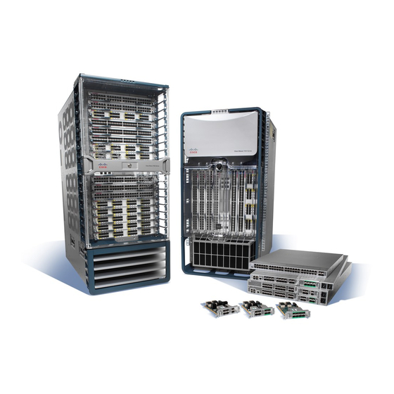
- Page 19 Cisco Nexus 7010 System The Cisco Nexus 7010 chassis has 10 slots that allow for two supervisor modules and up to eight I/O modules. The chassis also holds up to five fabric modules, two system fan trays, two fabric fan trays, up to three power supply units, and a cable management system.
-
Page 20: Overview
S e n d d o c u m e n t c o m m e n t s t o n e x u s 7 k - d o c f e e d b a c k @ c i s c o . c o m Figure 1-1 Standard Hardware Features on the Front and Sides of the Cisco Nexus 7010 Chassis Door for the cable management area... - Page 21 S e n d d o c u m e n t c o m m e n t s t o n e x u s 7 k - d o c f e e d b a c k @ c i s c o . c o m Figure 1-2 Optional Hardware Features on the Front Side of the Cisco Nexus 7010 Chassis Mid-frame door assembly...
- Page 22 You must install the Cisco Nexus 7010 system chassis in a four-post 19-inch EIA rack that meets the following specifications: Mounting rails that conform to the English universal hole spacing as specified in •...
- Page 23 Failure to stabilize the rack can cause the rack to tip over. Statement 1048 Figure 1-4 One Cisco Nexus 7010 Chassis Installed in a Four-Post Rack Install the first chassis at the bottom of the rack for maximum stability.
-
Page 24: Cisco Nexus 7018 System
Cisco Nexus 7018 System The Cisco Nexus 7018 chassis has 18 slots that allow for two supervisor modules and up to 16 I/O modules. The chassis also holds up to five fabric modules, two fan trays, up to four power supply units, and a cable management system. - Page 25 S e n d d o c u m e n t c o m m e n t s t o n e x u s 7 k - d o c f e e d b a c k @ c i s c o . c o m Figure 1-6 Standard Hardware Features on the Front and Sides of the Cisco Nexus 7018 Chassis System status LEDs...
- Page 26 Cable Management System for the 7018 Chassis System status LEDs (These LEDs show the Top hood system status displayed by the chassis LEDs.) Upper cable management assemblies Lower cable management assemblies Cisco Nexus 7000 Series Hardware Installation and Reference Guide OL-18634-01...
- Page 27 S e n d d o c u m e n t c o m m e n t s t o n e x u s 7 k - d o c f e e d b a c k @ c i s c o . c o m Figure 1-8 Optional Front Door for the Cisco Nexus 7018 Chassis Front doors Air intake frame for power supply units Cisco Nexus 7000 Series Hardware Installation and Reference Guide OL-18634-01...
- Page 28 S e n d d o c u m e n t c o m m e n t s t o n e x u s 7 k - d o c f e e d b a c k @ c i s c o . c o m Figure 1-9 Standard Hardware Features on the Back of the Cisco Nexus 7018 Chassis Fabric modules (up to 5)
- Page 29 • chassis installation and 87.5 inches (222.2 cm). Install the Cisco Nexus 7018 chassis at the lowest possible RU on the rack for stability, as shown in Figure 1-10. If there is another device in the rack, install the heaviest one at the bottom.
-
Page 30: Preparing The Site
Installation of the equipment must comply with local and national electrical codes. Statement 1074 Before you can install a Cisco Nexus 7000 Series system, you must prepare the site for the installation. You must make sure that the altitude, temperature, humidity, air quality, airflow, electromagnetic and radio frequency interference, floor structure, power, and earth grounding of the installation site all meet the requirements of the Cisco Nexus 7000 Series system that you are installing. -
Page 31: Safety Guidelines
19-inch EIA rack, and attach two bottom-support rails, you can begin installing the Cisco Nexus 7000 Series system. To install the system, you must load the chassis onto a mechanical lift, use the mechanical lift to position and elevate the chassis at its bottom-support rails on a rack or cabinet, push the chassis onto the rack or cabinet, and then secure the chassis to the rack or cabinet. -
Page 32: Replacing Components
S e n d d o c u m e n t c o m m e n t s t o n e x u s 7 k - d o c f e e d b a c k @ c i s c o . c o m Replacing Components While the Cisco Nexus 7000 Series system is operational, you can replace any I/O module or any one of the following components if they are redundant: Power supply •... -
Page 33: Installing A Cisco Nexus 7010 Chassis
C H A P T E R Installing a Cisco Nexus 7010 Chassis This chapter describes how to install a new or relocated Cisco Nexus 7010 chassis in a rack or cabinet. For information about installing a Cisco Nexus 7018 chassis, see Chapter 3, “Installing a Cisco Nexus... -
Page 34: Installing A Four-Post Rack Or Cabinet
Before you install the Cisco Nexus 7010 chassis, you must install a standard four-post, 19-inch EIA data center rack (or a cabinet that contains such a rack) that meets the requirements listed in the Cisco Nexus 7000 Series Site Preparation Guide. To maximize safety, you should do the following for the rack: •... -
Page 35: Unpacking And Inspecting A New Device
Unpacking and Inspecting a New Device Before you install a new Cisco Nexus 7010 chassis, you need to unpack and inspect it to be sure that you have all the items that you ordered and verify that the device was not damaged during shipment. If anything is damaged or missing, contact your customer representative immediately. -
Page 36: Prerequisites For Attaching The Bottom-Support Rails
Before you can attach the bottom-support rails, you must fully install the rack or cabinet, and should, for maximum stability, bolt the rack or cabinet to the concrete subfloor. If anything lighter than the Cisco Nexus 7010 system is already installed in the rack, you should make sure that it is positioned above where you will be installing the Cisco Nexus 7010 system. - Page 37 Position one of the two adjustable bottom-support rails at the lowest possible RU. If you are installing a chassis above another Cisco Nexus 7010 chassis, position the rail 36.75 inches (93.4 cm) (21 RU) above the bottom-support rails for the lower chassis as shown in Figure 2-1.
- Page 38 Use a Phillips screwdriver to screw in three M6 x 19 mm or 12-24 x 3/4 in. Phillips screws on each end Step 2 of each rail (using a total of 12 screws for both brackets) as shown in Figure 2-2. Cisco Nexus 7000 Series Hardware Installation and Reference Guide OL-18634-01...
-
Page 39: Installing The Chassis
3 12-24 x 3/4 in. Phillips screws Installing the Chassis This section describes how to install the Cisco Nexus 7010 chassis in a rack or cabinet. These installation steps include transporting the chassis, elevating the chassis to the rack using a mechanical lift, pushing the chassis onto the rack, and then securing the chassis to the rack. -
Page 40: Required Tools And Equipment
Before you install the chassis, you must make sure that the following items are available for the installation: • Data center ground is accessible where you are installing the Cisco Nexus 7010 chassis • Four-post, 19-inch, EIA rack or cabinet that includes such a rack For more information on the rack or cabinet, see the “Installing a Four-Post Rack or Cabinet”... - Page 41 You should also have at least four people to push the chassis, which can weigh up to 550 lbs (250 kg), onto and off the mechanical lift and rack. Installing the Chassis To install a Cisco Nexus 7010 chassis in a four-post rack or cabinet, follow these steps: Step 1 Load the chassis onto a mechanical lift as follows: Position the mechanical lift next to the shipping pallet that holds the chassis.
- Page 42 Use a Phillips screwdriver to screw in four M6 x 19-mm or 12-24 x 3/4-inch screws in each of the two Step 5 chassis mounting brackets (use a total of eight screws for two mounting brackets) as shown in Figure 2-4. Cisco Nexus 7000 Series Hardware Installation and Reference Guide 2-10 OL-18634-01...
-
Page 43: Prerequisites For Grounding The Chassis
Grounding the Cisco Nexus 7010 Chassis The Cisco Nexus 7010 system is grounded through the AC power supply cables and one of two grounding connections on the chassis. The AC power supply cables provide a connection to an earth ground whenever you connect the AC power to the system. - Page 44 Before you can ground the chassis, you must have a connection to the earth ground for the data center building. If you installed the Cisco Nexus 7010 chassis into a bonded rack (see the rack manufacturer’s instructions for more information) that now has a connection to the data center earth ground, you can ground the chassis by connecting its grounding ports to the rack.
- Page 45 Figure 2-6 Grounding Port on the Front of the Cisco Nexus 7010 Chassis Grounding port Cisco Nexus 7000 Series Hardware Installation and Reference Guide...
-
Page 46: Connecting Your Esd Strap To The Chassis
S e n d d o c u m e n t c o m m e n t s t o n e x u s 7 k - d o c f e e d b a c k @ c i s c o . c o m Figure 2-7 Grounding Port on the Rear of the Cisco Nexus 7010 Chassis Ground... - Page 47 S e n d d o c u m e n t c o m m e n t s t o n e x u s 7 k - d o c f e e d b a c k @ c i s c o . c o m Figure 2-8 ESD Grounding Ports on the Front of the Cisco Nexus 7010 Chassis ESD port...
-
Page 48: Installing And Formatting Compactflash Cards
ESD port Installing and Formatting CompactFlash Cards Each supervisor module on a Cisco Nexus 7000 Series device is shipped with a CompactFlash card installed in the LOG FLASH reader. The EXPANSION FLASH reader is left empty, but you can optionally install a card in that reader. For the card to function with the reader, you must make sure that it is either formatted for the reader before installing it or format it after installing it. - Page 49 Make sure that the card is fully inserted inside the reader. If the card is fully inserted, either format the card (see the Cisco NX-OS Fundamentals Configuration Guide, Release 4.0) or replace the card with another card that is properly formatted for the reader (see the “Replacing a CompactFlash...
-
Page 50: Chapter 2 Installing A Cisco Nexu 7010 Chassi
S e n d d o c u m e n t c o m m e n t s t o n e x u s 7 k - d o c f e e d b a c k @ c i s c o . c o m Cisco Nexus 7000 Series Hardware Installation and Reference Guide... -
Page 51: Required Tools
C H A P T E R Installing a Cisco Nexus 7018 Chassis This chapter describes how to install a new or relocated Cisco Nexus 7018 chassis in a rack or cabinet. For information about installing a Cisco Nexus 7010 chassis, see Chapter 2, “Installing a Cisco Nexus... -
Page 52: Preparing To Install The Device
Before you install the device, you must install a standard four-post, 19-inch EIA data center rack (or in a cabinet that contains such a rack) that meets the requirements listed in the Cisco Nexus 7000 Series Site Preparation Guide. To maximize safety, you should do the following for the rack: Bolt the rack to the concrete subfloor before moving the Cisco Nexus 7018 chassis onto it. -
Page 53: Installing The Bottom-Support Rails On The Rack
Unpacking and Inspecting a New Chassis Before you install a new Cisco Nexus 7018 chassis, you need to unpack and inspect it to be sure that you have all the items that you ordered and verify that the device was not damaged during shipment. If anything is damaged or missing, contact your customer representative immediately. - Page 54 Nexus 7018 system is already installed in the rack, you should make sure that it is positioned above where you will be installing the Nexus 7000 Series system. Also, you must have the bottom-support rail kit, which ships with the Nexus 7000 Series accessory kit. The distance between the front and rear mounting brackets on the rack or cabinet must be between 24 and 32 inches (61.0 and 81.3 cm).
- Page 55 Make sure that the two bottom-support rails are level with one another. If they are not level, adjust the Note higher rail down to the level of the lower rail. Figure 3-1 Positioning the Bottom-Support Rails Cisco Nexus 7000 Series Hardware Installation and Reference Guide OL-18634-01...
-
Page 56: Installing The Chassis
This section describes how to install the chassis (transporting and elevating the chassis to the rack using a mechanical lift, pushing it onto the rack, and then securing it to the rack). Cisco Nexus 7000 Series Hardware Installation and Reference Guide OL-18634-01... -
Page 57: Prerequisites For Installing The Chassis
“Unpacking and Inspecting a New Chassis” section on page 3-3. Required Tools and Equipment You need the following tools and equipment to install the Nexus 7000 Series chassis: Mechanical lift capable of lifting at least 700 lbs (318 kg) •... -
Page 58: Installing The Chassis
Note onto and off the mechanical lift and rack. Installing the Chassis To install a Cisco Nexus 7018 chassis in a four-post rack or cabinet, follow these steps: Step 1 Load the chassis onto a mechanical lift as follows: Position the mechanical lift next to the shipping pallet that holds the chassis. - Page 59 Use a Phillips screwdriver to screw in eight M6 x 19-mm or 12-24 x 3/4-inch screws in each of the two Step 5 chassis mounting brackets (use a total of 16 screws for two mounting brackets) as shown in Figure 3-4. Cisco Nexus 7000 Series Hardware Installation and Reference Guide OL-18634-01...
- Page 60 Eight M6 x 19 mm or 10-24 x 3/4 in. Phillips screws used to attach each side bracket to a front mounting rail (use a total of 10 screws) Cisco Nexus 7000 Series Hardware Installation and Reference Guide 3-10 OL-18634-01...
-
Page 61: Grounding The Cisco Nexus 7018 Chassis
S e n d d o c u m e n t c o m m e n t s t o n e x u s 7 k - d o c f e e d b a c k @ c i s c o . c o m Grounding the Cisco Nexus 7018 Chassis The Cisco Nexus 7018 system is grounded through the AC power supply cables and one of two grounding connections on the chassis. The AC power supply cables provide a connection to an earth ground whenever you connect the AC power to the system. -
Page 62: Connecting The System Ground
Ensure that the grounding lug and the grounding wire do not interfere with other device hardware or rack equipment. Cisco Nexus 7000 Series Hardware Installation and Reference Guide 3-12 OL-18634-01... -
Page 63: Connecting Your Esd Strap To The Chassis
Connecting Your ESD Strap to the Chassis After you connect the chassis to the earth ground, you can ground your ESD strap by plugging it into the ESD port shown in Figure 3-7. Cisco Nexus 7000 Series Hardware Installation and Reference Guide 3-13 OL-18634-01... -
Page 64: Installing The Cable Management Assemblies
ESD port Installing the Cable Management Assemblies After you have fully installed the Cisco Nexus 7018 device chassis in the rack or cabinet (see the “Installing the Chassis” section on page 3-6), you can install the cable management assemblies on the front of the chassis. - Page 65 Attach an upper cable management assembly (800-31342-01) onto the two hooks that protrude from the Step 2 upper half of the left rack-mount bracket that is attached to the Cisco Nexus 7018 device chassis, and loosely fasten the assembly to the chassis with four flat-head M4x10 screws as shown in Figure 3-9.
- Page 66 Repeat Step 1 and Step 2 to loosely attach a lower cable management assembly and an upper cable Step 3 management assembly to the right rack-mount bracket. When completed, the chassis will appear as shown in Figure 3-10. Cisco Nexus 7000 Series Hardware Installation and Reference Guide 3-16 OL-18634-01...
- Page 67 Figure 3-11. Push the top piece so that its alignment pins enter the alignment holes and the top hood rests against the chassis. Cisco Nexus 7000 Series Hardware Installation and Reference Guide 3-17 OL-18634-01...
- Page 68 Positioning the Top Hood with the Upper Cable Management Assemblies and the Device Chassis Alignment pins Alignment holes Use four M4x8 pan-head screws to loosely fasten the hood to the chassis as shown in Figure 3-11. Step 5 Cisco Nexus 7000 Series Hardware Installation and Reference Guide 3-18 OL-18634-01...
-
Page 69: Installing The Front Door And Air Intake Frame
Also, make sure that the cable management assemblies are aligned to the vertical sides of the chassis and that the cable management hood is level when you install those components. Cisco Nexus 7000 Series Hardware Installation and Reference Guide 3-19... - Page 70 S e n d d o c u m e n t c o m m e n t s t o n e x u s 7 k - d o c f e e d b a c k @ c i s c o . c o m To install the front door and air intake frame to the Cisco Nexus 7018 cable management system, follow...
- Page 71 Screw holes on the cable management assembly. Step 3 Position the hinge bracket (700-28491-01) at the bottoms of both cable management assemblies and the chassis as shown in Figure 3-15. Cisco Nexus 7000 Series Hardware Installation and Reference Guide 3-21 OL-18634-01...
- Page 72 Positioning the Hinge Bracket to the Cable Management Assemblies and Chassis Alignment pins Alignment holes Attach the bracket to the chassis with eight loosely fastened M4x8 screws, as shown in Figure 3-16. Step 4 Cisco Nexus 7000 Series Hardware Installation and Reference Guide 3-22 OL-18634-01...
- Page 73 Fasten the four ball-point studs (51-5008-01), each one with a washer (49-0430-01), to the bottom Step 7 portion of the chassis, one stud by each corner of the air intake area as shown in Figure 3-17. Cisco Nexus 7000 Series Hardware Installation and Reference Guide 3-23 OL-18634-01...
- Page 74 Align the air intake frame to the four ball-point studs and press the frame onto the chassis as shown in Step 8 Figure 3-18. The captive screws on the air-intake frame should align with their screw holes in the chassis. Cisco Nexus 7000 Series Hardware Installation and Reference Guide 3-24 OL-18634-01...
- Page 75 The double-hinge door can be installed and opened on either side. The figures in this procedure show Note how to install the door on the left side first, but you can use the instructions to install it on either side. Cisco Nexus 7000 Series Hardware Installation and Reference Guide 3-25 OL-18634-01...
- Page 76 See Figure 3-20. This action locks the latches around the hinge pins so that you no longer need to hold the door onto the chassis. Cisco Nexus 7000 Series Hardware Installation and Reference Guide 3-26 OL-18634-01...
- Page 77 Open the door handle on the open side of the door until it clicks. This action opens the latches on the Step 13 open side of the door. See Figure 3-21. Cisco Nexus 7000 Series Hardware Installation and Reference Guide 3-27 OL-18634-01...
- Page 78 If you do not hear the latches click, press the door at the handle to fully close it and to activate the latches. Test the door to make sure that it is fully secured to the four hinge pins. Cisco Nexus 7000 Series Hardware Installation and Reference Guide 3-28...
-
Page 79: Installing And Formatting Compactflash Cards
Installing and Formatting CompactFlash Cards Each supervisor module on a Cisco Nexus 7018 system is shipped with a CompactFlash card installed in the LOG FLASH reader. The EXPANSION FLASH reader is left empty, but you can optionally install a card in that reader. - Page 80 Make sure that the card is fully inserted inside the reader. If the card is fully inserted, either format the card (see the Cisco NX-OS Fundamentals Configuration Guide, Release 4.0) or replace the card with another card that is properly formatted for the reader (see the “Replacing a CompactFlash...
-
Page 81: Chapter 4 Installing Power Supply Units
Installing Power Supply Units You can install two to three power supply units in the Cisco Nexus 7010 system and two to four power supply units in the Cisco Nexus 7018 system. In either system, you must fill each power supply bay with either a 6-kW or 7.5-kW power supply unit or cover the bay with a blank plate. -
Page 82: Connecting The Power Supply Units To Ac Power
If you do not have enough power supply units to fill all of the power supply bays, cover each empty Note power supply bay with a blank plate (Cisco part number 800-28658-01) and secure it by screwing in its captive screws to 69 N m (8 in-lbs). -
Page 83: Connecting 6-Kw Power Supply Units
Ensure that the power supply switch located on the front of the power supply is set at STBY. Step 1 Plug each power cable into separate AC power sources supplied by the data center. Step 2 Cisco Nexus 7000 Series Hardware Installation and Reference Guide OL-18634-01... - Page 84 AC power source, and then turn the power switch back to ON. The Input and Output LEDs for the connected power supply units should be green and the Fault LED should be off. Cisco Nexus 7000 Series Hardware Installation and Reference Guide OL-18634-01...
-
Page 85: Preparing For Connections
Connecting the Cisco Nexus 7000 Device to the Network This chapter describes how to connect the Cisco Nexus 7000 Series device (configure its IP address through a console, set up its management interface, and connect its Ethernet ports to the network) after it has been installed in its rack or cabinet. -
Page 86: C H A P T E R 5 Connecting The Cisco Nexus 7000 Device To The Network
COM1/AUX SERIAL PORT—Use this port if you are using a modem. • You can find this cable in the console cable connector kit, which is part of the accessory kit for the Cisco Nexus 7000 Series device . Cisco Nexus 7000 Series Hardware Installation and Reference Guide... -
Page 87: Creating An Initial Device Configuration
• Minimizes or avoids the use of consecutive characters (such as “abcd”) • Minimizes or avoids repeating characters (such as “aaabbb”) Does not contain recognizable words from the dictionary • Cisco Nexus 7000 Series Hardware Installation and Reference Guide OL-18634-01... -
Page 88: Setting Up The Management Interface
The software asks if you need to save the configuration. Enter yes. Step 8 You can now set up the management interface for each supervisor module on the Cisco Nexus 7000 Series device. Setting Up the Management Interface The Cisco Nexus 7000 Series supervisor management port (MGMT ETH) provides out-of-band management, which enables you to use the CLI or the Data Center Network Manager (DCNM) interface to manage the device by its IP address. -
Page 89: Connecting The Supervisor Cmp Port
Connect the other end of the cable to a 10/100/1000 Ethernet port on the network device. Connecting the Supervisor CMP Port The CMP, which is included on the Cisco Nexus 7000 Series supervisor module, is a secondary, lightweight processor that provides a second network interface to the system for use even when the Control Processor (CP) is not reachable. -
Page 90: Connecting Or Disconnecting A 1000Base-T Port
Installing a Transceiver, page 5-7 • Removing a Transceiver, page 5-7 • Connecting a Fiber-Optic Cable with a Transceiver, page 5-8 Disconnecting a Fiber-Optic Cable From a Transceiver, page 5-8 • Cisco Nexus 7000 Series Hardware Installation and Reference Guide OL-18634-01... -
Page 91: Installing A Transceiver
S e n d d o c u m e n t c o m m e n t s t o n e x u s 7 k - d o c f e e d b a c k @ c i s c o . c o m Installing a Transceiver Use only Cisco SFP+ transceivers on the Cisco Nexus 7000 Series 32-port 10-Gigabit Ethernet modules Note and use only Cisco SFP transceivers on the Cisco Nexus 7000 Series 48-port 1-Gigabit Ethernet modules. -
Page 92: Connecting A Fiber-Optic Cable With A Transceiver
To remove the cable, follow these steps: Attach an ESD-preventative wrist strap and follow its instructions for use. Step 1 Record the cable and port connections for later reference. Step 2 Cisco Nexus 7000 Series Hardware Installation and Reference Guide OL-18634-01... -
Page 93: Maintaining Transceivers And Fiber-Optic Cables
Inspect routinely for dust and damage. If you suspect damage, clean and then inspect fiber ends • under a microscope to determine if damage has occurred. Cisco Nexus 7000 Series Hardware Installation and Reference Guide OL-18634-01... - Page 94 S e n d d o c u m e n t c o m m e n t s t o n e x u s 7 k - d o c f e e d b a c k @ c i s c o . c o m Cisco Nexus 7000 Series Hardware Installation and Reference Guide...
-
Page 95: Displaying The Device Hardware Inventory
Displaying the Device Hardware Inventory You can display information about the field replaceable units (FRUs), including product IDs, serial numbers, and version IDs by entering the show inventory command. See Example 6-1. Cisco Nexus 7000 Series Hardware Installation and Reference Guide OL-18634-01... -
Page 96: Displaying The Device Hardware Inventory
4.0(1) [build 4.0(0.855)] [gdb] BIOS compile time: 10/15/07 kickstart image file is: bootflash:/ks855.S7 kickstart compile time: 10/12/2020 25:00:00 [02/02/2008 01:38:41] system image file is: bootflash:/is855.S7 system compile time: 1/27/2008 14:00:00 [02/02/2008 02:21:24] Cisco Nexus 7000 Series Hardware Installation and Reference Guide OL-18634-01... -
Page 97: Chapter 6 Managing The Device Hardware
Model number is N7K-M132XP-12 H/W version is 0.601 Part Number is 73-10899-06 Part Revision is 13 Manufacture Date is Year 12 Week 1 Serial number is JAB120101QA CLEI code is 0 Module3 empty Cisco Nexus 7000 Series Hardware Installation and Reference Guide OL-18634-01... - Page 98 Model number is N7K-AC-6.0KW H/W version is 1.0 Part Number is 341-0230-02 Part Revision is A0 Manufacture Date is Year 12 Week 5 Serial number is DTH1205T002 CLEI code is IPUPADBAAA Cisco Nexus 7000 Series Hardware Installation and Reference Guide OL-18634-01...
-
Page 99: Displaying The Device Serial Number
Displaying the Device Serial Number The serial number of your Cisco Nexus 7000 Series device can be obtained by looking at the serial number label on the back of the device (next to the power supply), or by entering the show sprom backplane 1 command. - Page 100 00 00 00 00 00 00 00 00 00 00 00 00 00 00 00 00 00 00 00 00 00 00 00 00 00 00 00 00 00 00 00 00 Cisco Nexus 7000 Series Hardware Installation and Reference Guide OL-18634-01...
-
Page 101: Displaying Power Usage Information
See Example 6-4. Note In a Cisco Nexus 7000 Series device, power usage is reserved for both supervisor modules regardless of whether one or both supervisor modules are present. Example 6-4 Displaying Power Management Information switch# show environment power... -
Page 102: Power Supply Configuration Modes
1.2 kW for the 110-V grid and 3.0 kW for the 220-V grid. The available power would be 3.6 kW (1.2 kW + 1.2 kW + 1.2 kW) and the reserve power would be 9.0 kW (3.0 kW + 3.0 kW + 3.0 kW). Cisco Nexus 7000 Series Hardware Installation and Reference Guide OL-18634-01... - Page 103 110-V input 1 power supply 1200 W — — — 2 power supply units 2400 W 1200 W — — 3 power supply units 3600 W 2400 W — — Cisco Nexus 7000 Series Hardware Installation and Reference Guide OL-18634-01...
- Page 104 For power supply redundancy, use the • Example: ps-redundant keyword. switch(config)# power redundancy-mode redundant For input source redundancy, use the • switch(config)# insrc-redundant keyword. For full redundancy, use the redundant keyword. • Cisco Nexus 7000 Series Hardware Installation and Reference Guide 6-10 OL-18634-01...
-
Page 105: Power Supply Configuration Guidelines
For example, suppose your system has the following setup: Cisco Nexus 7000 Series Hardware Installation and Reference Guide 6-11 OL-18634-01... - Page 106 (3 kW for one power supply unit plus 3 kW for the other power supply unit). The available power does not meet the device usage requirement, so you cannot power the entire device. Cisco Nexus 7000 Series Hardware Installation and Reference Guide 6-12...
- Page 107 9 kW (3 kW for three power supply units on a second grid). The available power meets the device usage requirements, so you can power up the entire device. Cisco Nexus 7000 Series Hardware Installation and Reference Guide 6-13 OL-18634-01...
-
Page 108: Information About Modules
• Supervisor Modules The Cisco Nexus 7010 device has one or two supervisor modules. When it has two supervisors, one supervisor is automatically active while the other is in standby mode. If the active supervisor goes down or is disconnected for replacement, the standby supervisor automatically becomes active. To understand... -
Page 109: I/O Modules
(you cannot access a file system on the active supervisor). I/O Modules Cisco Nexus 7000 Series devices support the following I/O modules in slots 1 through 4 and 7 through 48-port 10/100/1000 Ethernet module •... -
Page 110: Checking The State Of A Module
This module is the active supervisor module and the device is ready to be active configured. The HA switchover mechanism is enabled on the standby supervisor module. HA-standby Cisco Nexus 7000 Series Hardware Installation and Reference Guide 6-16 OL-18634-01... -
Page 111: Connecting To A Module
Shutting Down Modules This section includes the following topics: Shutting Down a Supervisor or I/O Module, page 6-18 • • Shutting Down a Fabric Module, page 6-18 Cisco Nexus 7000 Series Hardware Installation and Reference Guide 6-17 OL-18634-01... -
Page 112: Shutting Down A Supervisor Or I/O Module
Displaying Module Temperature, page 6-19 • Overview of Module Temperatures Built-in, automatic sensors are provided in all switches in the Cisco Nexus 7000 Series to monitor your device at all times. Each module (supervisor, I/O, and fabric) has temperature sensors with two thresholds: •... -
Page 113: Displaying Module Temperature
During this interval, the software monitors the temperature every 5 seconds and continuously sends system messages as configured. We recommend that you install dual supervisor modules. If you are using a Cisco Nexus 7000 Series device without dual supervisor modules, we recommend that you immediately replace the fan module if just one fan is not working. -
Page 114: Displaying Environment Information
Temperature: -------------------------------------------------------------------- Module Sensor MajorThresh MinorThres CurTemp Status (Celsius) (Celsius) (Celsius) -------------------------------------------------------------------- Outlet1 (s1) Outlet2 (s2) Intake (s3) EOBC_MAC(s4) (s5) Crossbar(s6) Arbiter (s7) CTSdev1 (s8) InbFPGA (s9) QEng1Sn1(s10) QEng1Sn2(s11) Cisco Nexus 7000 Series Hardware Installation and Reference Guide 6-20 OL-18634-01... -
Page 115: Reloading Modules
You can reload the entire device, reset specific modules in the device, or reload the image on specific modules in the device. This section includes the following topics: Reloading the Device, page 6-22 • • Power Cycling Modules, page 6-22 Cisco Nexus 7000 Series Hardware Installation and Reference Guide 6-21 OL-18634-01... -
Page 116: Reloading The Device
A particular switching module is reloaded when you enter The configured module information is the reload module number command. preserved. Cisco Nexus 7000 Series Hardware Installation and Reference Guide 6-22 OL-18634-01... -
Page 117: Purging The Module Configuration
Device A before using this IP address. Powering Off I/O Modules By default, all fabric modules are configured to be in the power up state. SUMMARY STEPS config t [no] poweroff module slot_number Cisco Nexus 7000 Series Hardware Installation and Reference Guide 6-23 OL-18634-01... -
Page 118: Information About Fan Trays
Information About Fan Trays Hot-swappable fan trays are provided in all devices in the Cisco Nexus 7000 Series to manage airflow and cooling for the entire device. Each fan tray contains multiple fans to provide redundancy. The device can continue functioning in the following situations: One or more fans fail within a fan tray—Even with multiple fan failures, the Cisco Nexus 7000... -
Page 119: Epld Configuration
If the fan is physically present but not working properly, the status is failure. • On the Cisco Nexus 7010, each system fan module has 15 fans. If the State field for one of these fans contains “failure” in the show environment fan command output, it also displays the number of the... -
Page 120: Supported Device Hardware
You must have administrator privileges to work with the Nexus 7000 Series device. Supported Device Operating Systems The Cisco Nexus 7000 Series device must be running the Cisco NX-OS operating system, which is used to perform the EPLD upgrades. Updated EPLDs Depending on the Cisco NX-OS release that you are using, the EPLDs that you download and reinstall can include newly updated EPLDs. - Page 121 1.13 Fabric Module (Cisco Nexus Power Manager 7010) Fabric Module (Cisco Nexus Power Manager 7018) Table 11 Complete List of EPLDs for the Cisco NX-OS Release 4.1(2) Module Type EPLD Device EPLD Version Supervisor module Power Manager 3.26 Inband Local Bus CPLD...
-
Page 122: Installation Guidelines
S e n d d o c u m e n t c o m m e n t s t o n e x u s 7 k - d o c f e e d b a c k @ c i s c o . c o m Installation Guidelines You can upgrade (or downgrade) EPLDs using CLI commands on the Cisco Nexus 7000 Series device. Follow these guidelines when you upgrade or downgrade EPLDs: •... -
Page 123: Preparing The Epld Images For Installation
Preparing the EPLD Images for Installation Before you can update the EPLD images for each of your system modules, you must determine the Cisco NX-OS version that your system is using, make sure that there is space for the new EPLD images, and download the images. - Page 124 Mar 20 16:37:59 2008 setip.sh Usage for bootflash://sup-local 572186624 bytes used 306606080 bytes free 878792704 bytes total Example 11 Determining the Amount of Available Slot0 Memory switch# dir slot0: Cisco Nexus 7000 Series Hardware Installation and Reference Guide 6-30 OL-18634-01...
-
Page 125: Upgrading Epld Images
6-31). Upgrading EPLD Images When you start upgrading the EPLD images for a module, the Cisco NX-OS software tries to list the current and new versions for each EPLD. If the module is installed and online, the software reports both the installed and new versions of each EPLD, and where there is a difference, the software will upgrade (or downgrade) to the new version when you confirm that the upgrade should occur. -
Page 126: Upgrading The Epld Images For I/O Or Standby Supervisor Modules
Upgrading EPLD images for an online I/O module can disrupt traffic going through that module. Caution To upgrade EPLDs for an I/O module or the standby supervisor module, follow these steps: Determine the slot number for each module. Step 1 switch# show module Cisco Nexus 7000 Series Hardware Installation and Reference Guide 6-32 OL-18634-01... - Page 127 A module reload or just pressing the ejector buttons on the module is not sufficient for this Note reset requirement. To reset the entire system, power cycle the system. • Cisco Nexus 7000 Series Hardware Installation and Reference Guide 6-33 OL-18634-01...
- Page 128 Install the EPLDs by entering the install module slot_number epld url command. switch# install module 5 epld bootflash:n7000-s1-epld.4.0.2.img EPLD image file , built on Fri May 16 20:36:39 2008 Cisco Nexus 7000 Series Hardware Installation and Reference Guide 6-34 OL-18634-01...
- Page 129 Do you want to continue (y/n) ? Y Module 5 EPLD upgrade is successful The Cisco Nexus 7000 Series system will reload as soon as the upgrade occurs. Step 4 For releases 4.0(2) or earlier, if you updated the power management EPLD image, you must reset the power for the module so that EPLD can take effect (this is not required for release 4.0(3) or later).
- Page 130 S e n d d o c u m e n t c o m m e n t s t o n e x u s 7 k - d o c f e e d b a c k @ c i s c o . c o m To upgrade EPLDs for a fabric module, follow these steps: Determine which fabric modules are present on the Cisco Nexus 7000 Series device. Step 1...
-
Page 131: Displaying The Epld Versions
Displaying EPLD Versions for an I/O or Supervisor Module To display all of the current EPLD versions on a specific I/O or supervisor module, use the show version module slot_number epld command as shown in Example Cisco Nexus 7000 Series Hardware Installation and Reference Guide 6-37 OL-18634-01... -
Page 132: Displaying The Available Epld Versions
To view the available EPLD versions, use the show version epld url command. switch# show version epld bootflash:n7000-s1-epld.4.0.2.img EPLD image file , built on Fri May 16 20:36:39 2008 Module Type EPLD Device Version --------------------------------------------------------------- Supervisor-1X Power Manager Cisco Nexus 7000 Series Hardware Installation and Reference Guide 6-38 OL-18634-01... -
Page 133: Default Settings
Power Manager Fan Controller Fan Controller Default Settings Table 6-12 lists the default hardware settings. Table 6-12 Default Hardware Parameters Parameters Default Power supply mode Power supply redundancy mode Cisco Nexus 7000 Series Hardware Installation and Reference Guide 6-39 OL-18634-01... - Page 134 S e n d d o c u m e n t c o m m e n t s t o n e x u s 7 k - d o c f e e d b a c k @ c i s c o . c o m Cisco Nexus 7000 Series Hardware Installation and Reference Guide...
-
Page 135: Troubleshooting
Technical Assistance Center (TAC). Getting Started Start the Cisco Nexus 7000 Series device by turning on the power at the power supply units to send power to the system fans, supervisor module, fabric modules, and I/O modules. During the startup phase, the STATUS LEDs on the supervisor and I/O modules are amber to indicate that the initialization process is in progress. -
Page 136: Chapter 7 Troubleshooting
Make sure that the captive screws on the power supply unit align with their holes in the chassis. Tighten the four captive screws to 8 lb. in. Turn the power switch to ON. Cisco Nexus 7000 Series Hardware Installation and Reference Guide OL-18634-01... -
Page 137: Troubleshooting The Fan Trays
The STATUS LED on a supervisor module is amber, red, or not lit. • The CMP STATUS LED on a supervisor module is amber or red. • An ACT LED on a supervisor module is not lit. • Cisco Nexus 7000 Series Hardware Installation and Reference Guide OL-18634-01... -
Page 138: Troubleshooting The Fabric Modules
The following conditions indicate problems with one or more fabric modules: • The FAB LED on the chassis is amber. • The STATUS LED on the fabric module is red. Cisco Nexus 7000 Series Hardware Installation and Reference Guide OL-18634-01... -
Page 139: Troubleshooting The I/O Modules
Loosen the captive screws on the I/O module until they are no longer in the chassis. Press the eject buttons on either end of the module. Simultaneously rotate out both ejector levers until the module is unseated from the midplane. Cisco Nexus 7000 Series Hardware Installation and Reference Guide OL-18634-01... -
Page 140: Contacting Customer Service
Brief explanation of the steps that you have already taken to isolate and resolve the problem • Note If you have CLI access, enter the show sprom all command to display the backplane contents. To contact TAC, go to http://www.cisco.com/warp/public/687/Directory/DirTAC.shtm and click Support. Cisco Nexus 7000 Series Hardware Installation and Reference Guide OL-18634-01... -
Page 141: Replacing A Power Supply Unit During Operations
Replacing a Power Supply Unit During Operations The Cisco Nexus 7000 Series devices use a load-balanced power supply that uses up to three or four power supply units that each convert up to 1.2 kW, 3 kW, 3.5 kW, 6 kW, or 7.5 kW of AC power to DC power for system operations. -
Page 142: C H A P T E R 8 Removal And Installation Procedures
Warning when servicing. Statement 1034 To replace a power supply unit while a Cisco Nexus 7000 Series device is operating, follow these steps: Step 1 Make sure that the power supply units not being replaced have their power switches turned to ON. - Page 143 Statement 1034 To install a power supply unit while a Cisco Nexus 7000 Series device is operating, follow these steps: Ensure that the power switch on the power supply unit is in the standby (STBY) position and that the AC Step 1 power cords are not plugged into the AC power supply.
-
Page 144: Replacing A Supervisor Module
S e n d d o c u m e n t c o m m e n t s t o n e x u s 7 k - d o c f e e d b a c k @ c i s c o . c o m Replacing a Supervisor Module The Cisco Nexus 7000 Series devices can be configured with one or two supervisor modules. If the system has two supervisor modules, you can replace one of the supervisors while the other one manages system operations. - Page 145 Pull the module out of its slot. Caution To prevent ESD damage, avoid touching the electronic circuitry and prevent anything else from coming in contact with the circuitry. Cisco Nexus 7000 Series Hardware Installation and Reference Guide OL-18634-01...
- Page 146 If you are inserting the module into a Cisco Nexus 7010 chassis, rotate the module 90 degrees clockwise. Step 13 Align the module to the chassis guides for the vacated slot (slot 5 or 6 on the Cisco Nexus 7010 chassis Step 14 or slot 9 or 10 on the Cisco Nexus 7018 chassis), and slide the module part way into the slot.
-
Page 147: Replacing A Supervisor Module In A Single-Supervisor System
5-5. Replacing a Supervisor Module in a Single-Supervisor System If you need to replace the supervisor in a single-supervisor Cisco Nexus 7000 Series system, you must shut down the system before replacing the supervisor. Hazardous voltage or energy is present on the backplane when the system is operating. Use caution Warning when servicing. -
Page 148: Replacing An I/O Module
If you are inserting the module into a Cisco Nexus 7010 chassis, rotate the module 90 degrees clockwise. Step 13 Align the module to the chassis guides for the vacated slot (slot 5 or 6 on a Cisco Nexus 7010 chassis or Step 14 slot 9 or 10 on a Cisco Nexus 7018 chassis), and slide the module part way into the slot. -
Page 149: Replacing An I/O Module
32-port 10 Gigabit Ethernet SFP+ module • You can replace each of these I/O modules with another module of the same type while the Cisco Nexus 7000 Series device is operational.To do this, you must first remove an I/O module from the chassis, then install a new or replacement I/O module in the newly vacated slot within a couple of minutes to maintain the designed airflow. - Page 150 To prevent ESD damage, avoid touching the electronic circuitry and prevent anything else from coming in contact with the circuitry. If you are removing the module from a Cisco Nexus 7010 chassis, rotate the module 90 degrees Step 9 counterclockwise so that it is horizontal (with the circuitry seen from above).
-
Page 151: Replacing A Fabric Module During System Operations
Replacing a Fabric Module During System Operations The Cisco Nexus 7000 Series devices have three to five fabric modules located on the backside of the chassis. You can replace one of these fabric modules at a time while the device is operating. - Page 152 On the replacement module, rotate the two ejector levers fully away from the face of the module. Step 10 If you are inserting the module into a Cisco Nexus 7018 chassis, turn the module 90 degrees clockwise. Step 11 Cisco Nexus 7000 Series Hardware Installation and Reference Guide...
-
Page 153: Replacing A Cisco Nexus 7010 System Fan Tray During System Operations
Step 15 Replacing a Cisco Nexus 7010 System Fan Tray During System Operations The Cisco Nexus 7010 system has two system fan trays located on the upper backside of the chassis (see Figure 1-3 on page 1-4). Hazardous voltage or energy is present on the backplane when the system is operating. Use caution Warning when servicing. -
Page 154: Replacing A Cisco Nexus 7010 Fabric Fan Tray
Tighten the captive screws to 8 in-lb. Step 8 Replacing a Cisco Nexus 7010 Fabric Fan Tray The Cisco Nexus 7010 system has two fabric fan trays located on the backside of the chassis immediately above the fabric modules (see Figure 1-3 on page 1-4). -
Page 155: Replacing A Compactflash Card
S e n d d o c u m e n t c o m m e n t s t o n e x u s 7 k - d o c f e e d b a c k @ c i s c o . c o m To replace a Cisco Nexus 7010 fabric fan tray, follow these steps: Place an antistatic mat or antistatic foam where you can place the fan trays. - Page 156 Make sure that the card is fully inserted inside the reader. If the card is fully inserted, either format the card (see the Cisco NX-OS Fundamentals Configuration Guide, Release 4.0) or replace the card with another card that is properly formatted for the reader.
-
Page 157: Installing The Front Doors And Frame Assembly
Align each of the two front doors on a side of the mid frame area, and attach it by screwing in three Step 1 screws as shown in Figure 8-7. Cisco Nexus 7000 Series Hardware Installation and Reference Guide 8-17 OL-18634-01... - Page 158 S e n d d o c u m e n t c o m m e n t s t o n e x u s 7 k - d o c f e e d b a c k @ c i s c o . c o m Figure 8-7 Installing the Front Doors Cisco Nexus 7000 Series Hardware Installation and Reference Guide 8-18 OL-18634-01...
- Page 159 Re-align the EMI frame to the air intake area on the chassis and screw its four captive screws to the chassis, and tighten the captive screws to 8 in. lbs. Cisco Nexus 7000 Series Hardware Installation and Reference Guide 8-19...
-
Page 160: Replacing The Cisco Nexus 7010 System Air Filter
You can replace the optional air filter while the Nexus 7010 system is operational. Note Only the Cisco Nexus 7010 device includes an optional air filter. To replace the air filter, follow these steps: On the left and right side of the existing air filter, loosen the two captive screws so they are no longer Step 1 attached to the chassis. - Page 161 EMI frame bracket. Release the spring pin and make sure that it holds the air filter on to the EMI frame. Screw in and tighten both captive screws, one on each side of the air filter. Step 7 Cisco Nexus 7000 Series Hardware Installation and Reference Guide 8-21 OL-18634-01...
- Page 162 S e n d d o c u m e n t c o m m e n t s t o n e x u s 7 k - d o c f e e d b a c k @ c i s c o . c o m Cisco Nexus 7000 Series Hardware Installation and Reference Guide...
-
Page 163: Appendix
Technical Specifications This appendix describes the technical specifications for the Nexus 7000 system and includes these sections: Environmental Specifications for the Cisco Nexus 7000 Series Systems, page A-1 • Physical Specifications for the Cisco Nexus 7000 Series Devices, page A-2 •... -
Page 164: Appendix A Technical Specification
Cisco Nexus 7018 17.3 inches (43.9 cm) 38.0 inches (96.5 cm) 43.75 inches (111.1 cm) (25.0 RU) The height includes the bottom-support rail. The Cisco Nexus 7010 component weights, quantities, and mean time between failures (MTBF) are listed in Table... -
Page 165: Power Specifications For The Cisco Nexus 7000 Series Devices
Power Specifications for the Cisco Nexus 7000 Series Devices The number of power supplies that a Cisco Nexus 7000 Series switch requires depends on the quantities and types of modules that you include in the switch chassis. the type of power supply unit that you are using, and the power redundancy mode that you are using. -
Page 166: Power Supply Configuration Modes
Technical Specifications Power Specifications for the Cisco Nexus 7000 Series Devices S e n d d o c u m e n t c o m m e n t s t o n e x u s 7 k - d o c f e e d b a c k @ c i s c o . c o m... - Page 167 The amount of power available for use with your Cisco Nexus 7000 Series device depends on the number of power supply units, input voltage used, and the power mode used. To determine the amount of...
- Page 168 3600 W — — 1. A fourth power supply unit can be added to only the Cisco Nexus 7018 device. The Cisco Nexus 7010 holds up to three power supply units. Table A-8 Power Availability for 7.5-kW Power Supply Units...
-
Page 169: Power Supply Cable Specifications
CAB-AC-16A-AUS Power Cord and Connectors for the 6-kW Power Supply Unit Cordset rating: 16 A, 250 V Length: 14 ft 0 in. (4.26 m) Plug: AU20S3 Connector: IEC 60320 C19 Cisco Nexus 7000 Series Hardware Installation and Reference Guide OL-18634-01... - Page 170 CAB-AC-2500W-INT Power Cord and Connectors for the 6-kW Power Supply Unit Cordset rating: 16 A, 250 V Length: 14 ft 0 in. (4.26 m) Plug: IEC 309 Connector: IEC 60320 C19 Cisco Nexus 7000 Series Hardware Installation and Reference Guide OL-18634-01...
- Page 171 CAB-AC-C6K-TWLK Power Cord and Connectors for the 6-kW Power Supply Unit Cordset rating: 16 A, 250 V Length: 14 ft 0 in. (4.26 m) Plug: NEMA L6-20 Connector: IEC 60320 C19 Cisco Nexus 7000 Series Hardware Installation and Reference Guide OL-18634-01...
- Page 172 7.5 kW Power Supply AC Power Cords Local Cord rating Power cord reference illustration Japan and North America 30 A, 250 VAC Figure A-11 International 32 A, 250 VAC Figure A-12 Cisco Nexus 7000 Series Hardware Installation and Reference Guide A-10 OL-18634-01...
-
Page 173: Chassis Clearances
For the Cisco Nexus 7018 switch, the side-to-side airflow requires 11 inches (27.9 cm) of space on each side of the switch (or 22 inches [55.8 cm] between Cisco Nexus 7018 switches). You can route the I/O cables on the left front side of the chassis, but on the right side, you can route cables only on the upper right side of the chassis. -
Page 174: Facility Cooling Requirements
Cisco Nexus 7018 dissipates up to 51,195 BTUs per hour • Chassis Airflow The Cisco Nexus 7000 Series switches use either front-to-back or side-to-side airflow for device cooling. The Cisco Nexus 7010 switch uses front-to-back airflow as shown in Figure... - Page 175 Airflow for cooling the power supply units To allow for the Cisco Nexus 7018 switch to take in air from the cold aisle and floor on the right side, you should route cables on the left front side of the device. If necessary, you can route cables on the upper right front side of the chassis, which leaves the lower right side open to cooling air from the cold aisle in front of the chassis.
- Page 176 S e n d d o c u m e n t c o m m e n t s t o n e x u s 7 k - d o c f e e d b a c k @ c i s c o . c o m For the clearances required on each side of the switch, see the “Chassis Clearances” section on page A-11. Cisco Nexus 7000 Series Hardware Installation and Reference Guide A-14 OL-18634-01...
-
Page 177: Appendix
S e n d d o c u m e n t c o m m e n t s t o n e x u s 7 k - d o c f e e d b a c k @ c i s c o . c o m A P P E N D I X Cable and Port Specifications This appendix specifies the cables and port connectors used with the Cisco Nexus 7000 Series devices. This appendix includes the following sections: Module Connectors, page B-1 •... -
Page 178: Sfp Transceivers
Receive Core Size Transceiver Type or type (nm) (dBm) Power (dBm) (microns) Cable Distance Table B-4 lists the environmental conditions and power requirement specifications for the 10-Gigabit Ethernet SFP+ transceivers. Cisco Nexus 7000 Series Hardware Installation and Reference Guide OL-18634-01... -
Page 179: Sfp Transceivers
S e n d d o c u m e n t c o m m e n t s t o n e x u s 7 k - d o c f e e d b a c k @ c i s c o . c o m Table B-4 Environmental Conditions and Power Requirement Specifications for the 1-Gigabit Ethernet SFP Transceivers Parameter Minimum Maximum Storage temperature Operating temperature Case temperature Module supply voltage Cisco Nexus 7000 Series Hardware Installation and Reference Guide OL-18634-01... - Page 180 S e n d d o c u m e n t c o m m e n t s t o n e x u s 7 k - d o c f e e d b a c k @ c i s c o . c o m Cisco Nexus 7000 Series Hardware Installation and Reference Guide...
-
Page 181: Appendix
A P P E N D I X Chassis and Module LEDs This appendix lists the Cisco Nexus 7000 Series system LEDs and describes the conditions they indicate for the chassis and each type of module installed in the chassis. -
Page 182: Appendix C Chassi And Module Led
The management port link is bad and has been disabled due to a hardware Amber failure. The module has not detected a signal. LINK Green The module has detected a link. The module does not detect a link. Cisco Nexus 7000 Series Hardware Installation and Reference Guide OL-18634-01... - Page 183 I/O module LEDs. Table C-3 I/O Module LEDs Status Description Blinking The operator has activated this LED to identify this module in the chassis. blue This module is not being identified. Cisco Nexus 7000 Series Hardware Installation and Reference Guide OL-18634-01...
- Page 184 The port is disabled by the operator or is not initializing. Blinking The port is faulty and disabled. orange The port is not active or the link is not connected. Cisco Nexus 7000 Series Hardware Installation and Reference Guide OL-18634-01...
- Page 185 Self-diagnostic tests have failed or another power supply failure has occurred. Blinking blue The operator has activated this LED to identify this module in the chassis. This module is not being identified. Cisco Nexus 7000 Series Hardware Installation and Reference Guide OL-18634-01...
- Page 186 The fan tray is receiving insufficient power. No power is going to the fan tray. Blinking blue The operator has activated this LED to identify this module in the chassis. This module is not being identified. Cisco Nexus 7000 Series Hardware Installation and Reference Guide OL-18634-01...
-
Page 187: Appendix
Powering Down the Cisco Nexus 7000 Series System To power down the Cisco Nexus 7000 Series system, turn the power switch on each power supply from Power to STBY, and then disconnect the power cords to each power supply. The system is powered down when the LEDs on each power supply are all off. -
Page 188: A P P E N D I X D Repacking The Cisco Nexus 7000 Series Device For Shipment
Repacking the System Components You should repack the Cisco Nexus 7000 Series system in the packing materials in which it was originally shipped. To make the Cisco Nexus 7000 Series lighter and easier to move, remove its power supply units and its optional features, such as the midframe doors, lower frame, and air filter. You should pack each of these components separately. -
Page 189: Repacking The Cisco Nexus 7010 Device
S e n d d o c u m e n t c o m m e n t s t o n e x u s 7 k - d o c f e e d b a c k @ c i s c o . c o m When you are handling the Cisco Nexus 7000 Series deivce or device components, you must follow the Caution ESD protocol at all times to prevent ESD damage. - Page 190 Appendix D Repacking the Cisco Nexus 7000 Series Device for Shipment Repacking the System Components S e n d d o c u m e n t c o m m e n t s t o n e x u s 7 k - d o c f e e d b a c k @ c i s c o . c o m Place your other hand underneath the power supply unit to support its weight and then remove the power supply unit from the chassis.
- Page 191 Appendix D Repacking the Cisco Nexus 7000 Series Device for Shipment Repacking the System Components S e n d d o c u m e n t c o m m e n t s t o n e x u s 7 k - d o c f e e d b a c k @ c i s c o . c o m...
- Page 192 Appendix D Repacking the Cisco Nexus 7000 Series Device for Shipment Repacking the System Components S e n d d o c u m e n t c o m m e n t s t o n e x u s 7 k - d o c f e e d b a c k @ c i s c o . c o m...
- Page 193 Appendix D Repacking the Cisco Nexus 7000 Series Device for Shipment Repacking the System Components S e n d d o c u m e n t c o m m e n t s t o n e x u s 7 k - d o c f e e d b a c k @ c i s c o . c o m...
- Page 194 Appendix D Repacking the Cisco Nexus 7000 Series Device for Shipment Repacking the System Components S e n d d o c u m e n t c o m m e n t s t o n e x u s 7 k - d o c f e e d b a c k @ c i s c o . c o m...
-
Page 195: Appendix
A P P E N D I X Site Preparation and Maintenance Records This appendix provides a site planning list to use when preparing your site for the Cisco Nexus 7000 system and includes these sections: Site Preparation Checklist, page E-1 •... -
Page 196: Contact And Site Information
E-2) to record contact and site information. Table E-2 Contact and Site Information Contact person Contact phone Contact e-mail Building/site name Data center location Floor location Address (line 1) Address (line 2) City State Cisco Nexus 7000 Series Hardware Installation and Reference Guide OL-18634-01... -
Page 197: A P P E N D I X E Site Preparation And Maintenance Records
Network-Related Information Device IP address Device IP netmask Hostname Domain name IP broadcast address Gateway/router address DNS address Table E-4 Module Information Slot Module Type Module Serial Number Notes Supervisor Supervisor Cisco Nexus 7000 Series Hardware Installation and Reference Guide OL-18634-01... - Page 198 S e n d d o c u m e n t c o m m e n t s t o n e x u s 7 k - d o c f e e d b a c k @ c i s c o . c o m Cisco Nexus 7000 Series Hardware Installation and Reference Guide...
-
Page 199: I N D E X
Cisco Nexus 7018 installing shelf brackets 2-6, 3-6 LEDs cable management assembly installation power redundancy modes 6-10 Cisco Nexus 7018 3-14 repacking chassis replacing airflow A-12 inspecting the Cisco Nexus 7010 Cisco Nexus 7000 Series Hardware Installation and Reference Guide IN-1 OL-18634-01... - Page 200 2-6, 3-6 MTBF expansion flash reader 2-16 overview power specifications clearances planning A-11 fabric modules combined mode 6-8, 6-11 configuration, purging 6-23 combined power mode description 6-15 LEDs Cisco Nexus 7000 Series Hardware Installation and Reference Guide IN-2 OL-18634-01...
- Page 201 2-1, 3-1, 4-1 grounding tools for Cisco Nexus 7010 Cisco Nexus 7010 2-11 tools for Cisco Nexus 7018 Cisco Nexus 7018 3-11 troubleshooting grounding pad inventory, displaying Cisco Nexus 7010 2-13 Cisco Nexus 7000 Series Hardware Installation and Reference Guide IN-3 OL-18634-01...
- Page 202 Cisco Nexus 7010 2-11 grounding for Cisco Nexus 7018 3-11 set up for Cisco Nexus 7010 set up for Cisco Nexus 7018 physical specifications shelf brackets 2-6, 3-6 Cisco Nexus 7000 Series Hardware Installation and Reference Guide IN-4 OL-18634-01...
- Page 203 6-22 power specifications resetting 6-21 saving to nonvolatile storage 6-22 shutting down 6-18 standby state 6-16 state descriptions 6-16 temperature, displaying 6-19 terms 6-14 troubleshooting verifying status 6-15 weight Cisco Nexus 7000 Series Hardware Installation and Reference Guide IN-5 OL-18634-01...
- Page 204 S e n d d o c u m e n t c o m m e n t s t o n e x u s 7 k - d o c f e e d b a c k @ c i s c o . c o m Cisco Nexus 7000 Series Hardware Installation and Reference Guide...