Table of Contents
Advertisement
Quick Links
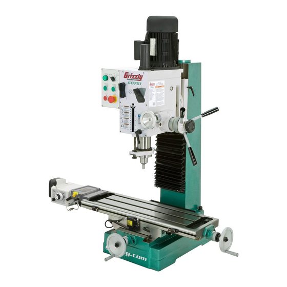
MODEL G0761
HEAVY-DUTY BENCHTOP
MILL/DRILL w/POWER FEED
& TAPPING
OWNER'S MANUAL
(For models manufactured since 10/13)
Copyright © MAy, 2014 By grizzly industriAl, inC.
WARNING: NO PORTION OF THIS MANUAL MAY BE REPRODUCED IN ANY SHAPE
OR FORM WITHOUT THE WRITTEN APPROVAL OF GRIzzLY INDUSTRIAL, INC.
#ts16056 printed in ChinA
V1.05.14
Advertisement
Table of Contents

Related Manuals for Grizzly G0761


Summary of Contents for Grizzly G0761
- Page 1 (For models manufactured since 10/13) Copyright © MAy, 2014 By grizzly industriAl, inC. WARNING: NO PORTION OF THIS MANUAL MAY BE REPRODUCED IN ANY SHAPE OR FORM WITHOUT THE WRITTEN APPROVAL OF GRIzzLY INDUSTRIAL, INC. #ts16056 printed in ChinA V1.05.14...
- Page 2 This manual provides critical safety instructions on the proper setup, operation, maintenance, and service of this machine/tool. Save this document, refer to it often, and use it to instruct other operators. Failure to read, understand and follow the instructions in this manual may result in fire or serious personal injury—including amputation, electrocution, or death.
-
Page 3: Table Of Contents
Table of Contents INTRODUCTION ..........2 installing/removing tooling ......24 Machine description ........2 installing tooling ............Contact info............ 2 removing tooling ............. Manual Accuracy ........... 2 spindle speed..........26 identification ........... 3 determining spindle speed ........Basic Controls ..........4 setting spindle speed .......... -
Page 4: Introduction
We want your feedback on this manual. What did you like about it? Where could it be improved? Please take a few minutes to give us feedback. Grizzly Documentation Manager P.O. Box 2069 Bellingham, WA 98227-2069 Email: manuals@grizzly.com Model G0761 (Mfd. Since 10/13) -
Page 5: Identification
Feed stop table X-Axis power Feed power Feed stop X-Axis y-Axis X-Axis handwheel handwheel y-Axis table locks table lock To reduce your risk of serious injury, read this entire manual BEFORE using machine. Model G0761 (Mfd. Since 10/13) -
Page 6: Basic Controls
G. STOP Button: stops spindle rotation. Figure 1. Control panel and spindle speed H. SPINDLE FORWARD Button: starts clock- controls. wise spindle rotation (as viewed from above). the spindle must be completely stopped before this button is pushed. Model G0761 (Mfd. Since 10/13) -
Page 7: Machine Data Sheet
Machine Data Sheet MACHINE DATA SHEET Customer Service #: (570) 546-9663 · To Order Call: (800) 523-4777 · Fax #: (800) 438-5901 MODEL G0761 HEAVY-DUTY BENCHTOP MILL/DRILL WITH POWER FEED AND TAPPING Product Dimensions: Weight................................716 lbs. Width (side-to-side) x Depth (front-to-back) x Height............... 49-5/8 x 30-3/4 x 57 in. - Page 8 The information contained herein is deemed accurate as of 5/14/2014 and represents our most recent product specifications. Model G0761 PAGE 2 OF 2 Due to our ongoing improvement efforts, this information may not accurately describe items previously purchased. Model G0761 (Mfd. Since 10/13)
-
Page 9: Section 1: Safety
Model G0761 (Mfd. Since 10/13) - Page 10 Contact our debris. Make sure they are properly installed, technical support at (570) 546-9663. undamaged, and working correctly. Model G0761 (Mfd. Since 10/13)
-
Page 11: Additional Safety For Mill/Drills
OFF to avoid a possible sudden startup once risk of entanglement, always allow spindle to stop on its own. do not stop spindle using your hand power is restored. or any other object. Model G0761 (Mfd. Since 10/13) -
Page 12: Section 2: Power Supply
To reduce the risk of these hazards, avoid over- loading the machine during operation and make sure it is connected to a power supply circuit that meets the requirements in the following section. -10- Model G0761 (Mfd. Since 10/13) -
Page 13: Grounding Instructions
If the plug does not fit the available receptacle, or the machine must be reconnected for use on a different type of circuit, the reconnection must be made by a qualified electrician and comply with all local codes and ordinances. -11- Model G0761 (Mfd. Since 10/13) -
Page 14: Section 3: Setup
Chuck Arbor r-8 x B16 ....... 1 • Brass hammer (Page 16) ......1 K. spindle sleeve Mt#3 x Mt#2 ....1 • Mineral spirits (Page 16) .... As needed Figure 3. small item inventory. -12- Model G0761 (Mfd. Since 10/13) -
Page 15: Cleanup
Figure 4. t23692 orange power degreaser. off the rest with the rag. repeat Steps 2–3 as necessary until clean, then coat all unpainted surfaces with a quality metal protectant to prevent rust. -13- Model G0761 (Mfd. Since 10/13) -
Page 16: Site Considerations
Only install in an Shadows, glare, or strobe effects that may distract access restricted location. or impede the operator must be eliminated. 31" ⁄ " ⁄ " Figure 5. Minimum working clearances. -14- Model G0761 (Mfd. Since 10/13) -
Page 17: Lifting & Placing
Lag Screw Flat Washer Machine Base Figure 6. recommended lifting strap position. Workbench Figure 8. example of a "direct Mount" setup. -15- Model G0761 (Mfd. Since 10/13) -
Page 18: Assembly
Figure 10. Figure 10. tapping drill chuck/arbor on block of wood. try to separate drill chuck and arbor by hand . if you can pull them apart, repeat this proce- dure. -16- Model G0761 (Mfd. Since 10/13) -
Page 19: Lubricating Mill/Drill
To test run the mill/drill: Clear all setup tools away from machine. Connect machine to power supply. power lamp should light. -17- Model G0761 (Mfd. Since 10/13) - Page 20 Congratulations! the Test Run is complete. Continue to the next subsection, Spindle Bearing Break-In. EMERGENCY STOP Button Figure 12. twisting eMergenCy stop button to reset it. -18- Model G0761 (Mfd. Since 10/13)
-
Page 21: Spindle Bearing Break-In
Continue with this process for each remain- ing speeds, working from lowest ot highest. Change headstock oil (refer to Lubrication on Page 31 for detailed instructions). the spindle break-in of the mill is now complete! -19- Model G0761 (Mfd. Since 10/13) -
Page 22: Section 4: Operations
Read books/magazines or get formal training before beginning any proj- ects. Regardless of the content in this sec- tion, Grizzly Industrial will not be held liable for accidents caused by lack of training. -20- Model G0761 (Mfd. Since 10/13) -
Page 23: Downfeed Controls
E. downfeed selector Knob adjustment knob (see “D” in Figure 13), it can be positioned anywhere within 0"–5". this is useful Coarse downfeed handle when performing the same operation multiple times or with tapping operations. -21- Model G0761 (Mfd. Since 10/13) -
Page 24: Headstock Movement
Figure 17. hex nut underneath headstock. using scale shown in Figure 16 as a guide, swivel headstock and retighten the three hex nuts to secure it. z-Axis Crank Figure 15. z-axis crank. tighten z-axis lock levers to secure setting. -22- Model G0761 (Mfd. Since 10/13) -
Page 25: Table Travel
Figure 20, then use the handwheel in front of the table in the same manner as the X-axis handwheel. thumb screw Figure 19. graduated dial and thumb screw. -23- Model G0761 (Mfd. Since 10/13) -
Page 26: X-Axis Power Feed
Note: The power feed must be connected to an independent, grounded 110V power supply to operate. Installing/Removing Tooling the Model g0761 includes the following spindle tools (see Figure 23): A. B16 Drill Chuck w/R-8 Arbor. Joined with the drill chuck. B. R-8–MT#3 Spindle Sleeve. used for Mt#3 tools and will accommodate tools with a tang. -
Page 27: Installing Tooling
Working from the top, thread drawbar by hand into tooling until it is snug, then use wrench to tighten it. Note: overtighten drawbar. Overtightening makes tool removal difficult and will damage arbor and threads. re-install drawbar cap. -25- Model G0761 (Mfd. Since 10/13) -
Page 28: Spindle Speed
Also, there are a large number of easy-to-use spindle speed calculators that can be found on the internet. these sources will help you take into account the applicable variables in order to deter- mine the best spindle speed for the operation. -26- Model G0761 (Mfd. Since 10/13) -
Page 29: Tapping Mode
10. slowly lower spindle until tap begins thread- ing into workpiece, then release pressure on the downfeed control. When the spindle dog makes contact with depth stop, spindle rotation will reverse and tap will unthread from hole. -27- Model G0761 (Mfd. Since 10/13) -
Page 30: Section 5: Accessories
To reduce this risk, only install accessories their lubricity under a variety of conditions—as recommended for this machine by Grizzly. well as reduce chatter or slip. Buy in bulk and save with 5-gallon quantities. - Page 31 Figure 35. Model sB1349 south Bend 16-pc. r-8 Collet set. Figure 33. t23964 Armor plate with Moly-d Multi-purpose grease. www.grizzly.com 1-800-523-4777 order online at or call -29- Model G0761 (Mfd. Since 10/13)
-
Page 32: Section 6: Maintenance
MAChine FroM poWer BeFore perForMing luBriCAtion! NOTICE Follow reasonable lubrication practices as outlined in this manual. Failure to do so could lead to premature failure of your machine and will void the warranty. -30- Model G0761 (Mfd. Since 10/13) -
Page 33: Headstock
Add oil until sight glass is halfway full, then disConneCt MAChine FroM poWer! replace fill plug. remove fill plug (see Figure 37). Clean up any spilled oil to reduce slipping hazards. Fill plug Figure 37. headstock oil fill plug. -31- Model G0761 (Mfd. Since 10/13) -
Page 34: Ball Oilers
(see headstock to access the entire length of the table Page 28 for offerings from grizzly). We do not and column ways for this procedure (see Figure recommend using metal needle or lance tips, as 40). -
Page 35: Quill Outside Surface
Figure 43. y-axis leadscrew. When dry, use a clean brush to apply a thin coat of oil to the leadscrew threads, then move the table through the X- and y-axis paths to distribute the oil. -33- Model G0761 (Mfd. Since 10/13) -
Page 36: Column Leadscrew, Nut, & Pinion Gear
Move the headstock up and down cleaning process. a few times to evenly distribute the lubricant. re-install rear cover. -34- Model G0761 (Mfd. Since 10/13) -
Page 37: Section 7: Service
8. Motor fan is rubbing on fan cover. 8. replace dented fan cover or damaged fan. 9. Motor bearings are at fault. 9. test by rotating shaft; rotational grinding/loose shaft requires bearing replacement. -35- Model G0761 (Mfd. Since 10/13) - Page 38 3. Check for proper cutting rotation for cutting tool. 4. Workpiece not secure. 4. properly clamp workpiece on table or in vise. 5. spindle extended too far down. 5. Fully retract spindle and lower headstock. this increases rigidity. -36- Model G0761 (Mfd. Since 10/13)
-
Page 39: Adjusting Gibs
Figure 47. X-axis leadscrew nut adjusting cap screw. X-Axis gib screw y-Axis gib screw (1 of 2) (1 of 2) Figure 46. location of table gib screws. -37- Model G0761 (Mfd. Since 10/13) -
Page 40: Tightening Return Spring Tension
If the return spring should come loose from the spring cap and rapidly unwind, laceration or impact inju- ries could occur. Always wear heavy leather gloves and safety glasses when adjusting the return spring tension. -38- Model G0761 (Mfd. Since 10/13) -
Page 41: Section 8: Wiring
Technical source. Support at (570) 546-9663. The photos and diagrams included in this section are best viewed in color. You can view these pages in color at www.grizzly.com. -39- Model G0761 (Mfd. Since 10/13) -
Page 42: Electrical Box & Control Panel Wiring
14NO 22NC 32NC 44NO 2A Fuse Ceramic 250V 2A Ø5 x 25 Ground Plate to Motor to tapping Ground Page 42) switches 6-15 Plug Page 42) (As Recommended) READ ELECTRICAL SAFETY -40- Model G0761 (Mfd. Since 10/13) ON PAGE 39! - Page 43 Electrical Box & Control Panel Wiring Figure 49. Control panel wiring. Figure 50. electrical box wiring. READ ELECTRICAL SAFETY -41- Model G0761 (Mfd. Since 10/13) ON PAGE 39!
-
Page 44: Motor & Tapping Switches Wiring
Ground Start Capacitor Capacitor 150 MFD 20 MFD 250 VAC 450 VAC Figure 51. Motor wiring. to electrical Box (Page 40) Tapping Switches Figure 52. tapping switch wiring. READ ELECTRICAL SAFETY -42- Model G0761 (Mfd. Since 10/13) ON PAGE 39! -
Page 45: Section 9: Parts
Please Note: We do our best to stock replacement parts whenever possible, but we cannot guarantee that all parts shown here are available for purchase. Call (800) 523-4777 or visit our online parts store at www.grizzly.com to check for availability. -
Page 46: Headstock Parts List
KEY 5 X 5 X 50 P0761095 CAP SCREW M8-1.25 X 25 P0761043 SET SCREW M6-1 X 12 P0761096 KNURLED THUMB SCREW M5-.8 X 12 P0761044 SPINDLE SHAFT P0761097 SPRING COVER FLAT WASHER 6MM -44- Model G0761 (Mfd. Since 10/13) - Page 47 DRAWBAR ASSEMBLY 7/16-20 X 17-3/4 P0761107 OUTER LOCK PLUNGER P0761120 ELECTRICAL CABINET P0761108 ADJUSTABLE HANDLE P0761121 ELECTRICAL CABINET FRONT COVER P0761109 SPEED SHIFT SHAFT (LH) P0761122 ELECTRICAL CABINET SIDE COVER P0761110 SPEED SHIFT ROCKER ARM (LH) -45- Model G0761 (Mfd. Since 10/13)
-
Page 48: Table & Column
Table & Column 274-2 274-1 274-4 274-3 274-5 275 276 -46- Model G0761 (Mfd. Since 10/13) - Page 49 CAP SCREW M6-1 X 16 P0761287 PHLP HD SCR M5-.8 X 12 P0761244 FLAT WASHER 6MM P0761288 Y-AXIS WAY COVER P0761245 CAP SCREW M5-.8 X 20 P0761289 TABLE SCALE P0761246 CAP SCREW M8-1.25 X 45 -47- Model G0761 (Mfd. Since 10/13)
-
Page 50: Electrical
P0761311 FUSE 2A 250V CERAMIC P0761305 E-STOP MINGER LA125H-BE 102C 22MM P0761312 GROUND PLATE P0761306 TRANSFORMER MTE JBK5-63VA 0-220V P0761313 TAPPING SWITCH JUCHE LXW16-16/51C P0761307 CONTACTOR SIEMENS 3TB41 24V P0761314 ELECTRICAL BOX MOUNTING BOARD -48- Model G0761 (Mfd. Since 10/13) -
Page 51: Accessories
405-1 P0761405-1 DRILL CHUCK KEY 8MM STD 11 SD-16MM P0761414 HEX WRENCH 3MM P0761406 SPINDLE SLEEVE MT#3-MT#2 P0761415 WRENCH 17 X 19MM OPEN-ENDS P0761407 DRILL CHUCK ARBOR R8-B16 P0761416 WRENCH 22 X 24MM OPEN-ENDS P0761408 SPINDLE SLEEVE R8-MT#3 -49- Model G0761 (Mfd. Since 10/13) -
Page 52: Labels & Cosmetics
Safety labels help reduce the risk of serious injury caused by machine hazards. If any label comes off or becomes unreadable, the owner of this machine MUST replace it in the original location before resuming operations. For replacements, contact (800) 523-4777 or www.grizzly.com. -50-... -
Page 53: Warranty Card
Would you recommend Grizzly Industrial to a friend? _____ Yes _____No Would you allow us to use your name as a reference for Grizzly customers in your area? Note: We never use names more than 3 times. _____ Yes _____No 10. - Page 54 FOLD ALONG DOTTED LINE Place Stamp Here GRIZZLY INDUSTRIAL, INC. P.O. BOX 2069 BELLINGHAM, WA 98227-2069 FOLD ALONG DOTTED LINE Send a Grizzly Catalog to a friend: Name_______________________________ Street_______________________________ City______________State______Zip______ TAPE ALONG EDGES--PLEASE DO NOT STAPLE...
-
Page 55: Warranty & Returns
WARRANTY & RETURNS Grizzly Industrial, Inc. warrants every product it sells for a period of 1 year to the original purchaser from the date of purchase. This warranty does not apply to defects due directly or indirectly to misuse, abuse, negligence, accidents, repairs or alterations or lack of maintenance.