Table of Contents
Advertisement
Quick Links
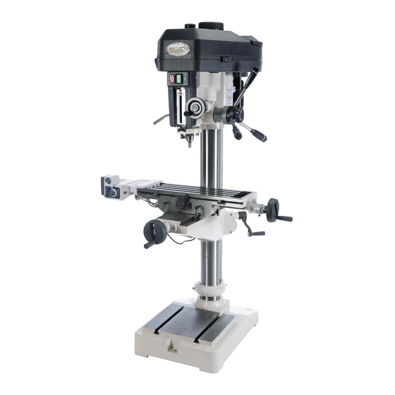
MODEL G0810
16" DRILL PRESS w/CROSS-
SLIDE TABLE & POWER FEED
OWNER'S MANUAL
(For models manufactured since 10/15)
COPYRIGHT © AUGUST, 2016 BY GRIZZLY INDUSTRIAL, INC.
WARNING: NO PORTION OF THIS MANUAL MAY BE REPRODUCED IN ANY SHAPE
OR FORM WITHOUT THE WRITTEN APPROVAL OF GRIZZLY INDUSTRIAL, INC.
#WK17973 PRINTED IN TAIWAN
V1.08.16
Advertisement
Table of Contents

Related Manuals for Grizzly G0810


Summary of Contents for Grizzly G0810
- Page 1 (For models manufactured since 10/15) COPYRIGHT © AUGUST, 2016 BY GRIZZLY INDUSTRIAL, INC. WARNING: NO PORTION OF THIS MANUAL MAY BE REPRODUCED IN ANY SHAPE OR FORM WITHOUT THE WRITTEN APPROVAL OF GRIZZLY INDUSTRIAL, INC. #WK17973 PRINTED IN TAIWAN V1.08.16...
- Page 2 This manual provides critical safety instructions on the proper setup, operation, maintenance, and service of this machine/tool. Save this document, refer to it often, and use it to instruct other operators. Failure to read, understand and follow the instructions in this manual may result in fire or serious personal injury—including amputation, electrocution, or death.
-
Page 3: Table Of Contents
Table of Contents INTRODUCTION ..........2 SECTION 5: ACCESSORIES ......34 Contact Info............ 2 SECTION 6: MAINTENANCE ......37 Manual Accuracy ........... 2 Schedule ............37 Identification ........... 3 Cleaning & Protecting ........37 Controls & Components ......... 4 Lubrication ........... 38 Machine Data Sheet ........ -
Page 4: Introduction
ID label (see below). This information is required for us to provide proper tech support, and it helps us determine if updated documenta- tion is available for your machine. Manufacture Date Serial Number Model G0810 (Mfd. Since 10/15) -
Page 5: Identification
Manual Before Operating Drill Press. Wear eye protection. b) Do not wear gloves, necktie, or loose clothing. Clamp workpiece or brace against column to prevent rotation. d) Use recommended speed for drill accessory and workpiece material. Model G0810 (Mfd. Since 10/15) -
Page 6: Controls & Components
0.001" increments. One complete revolution equals 0.100". Headstock H. Coarse Downfeed Levers: Provide coarse control over vertical spindle travel. Downfeed Selector Knob: Engages/disen- gages fine downfeed handwheel. Figure 1. Headstock controls & components. Model G0810 (Mfd. Since 10/15) - Page 7 X/Y Cross Table Power Feed Identification Model G0810 is equipped with a power feed unit for X-axis table movement. Refer to Figure 3 and the following descriptions to understand the func- tions of the various components of the power feed system.
-
Page 8: Machine Data Sheet
Machine Data Sheet MACHINE DATA SHEET Customer Service #: (570) 546-9663 · To Order Call: (800) 523-4777 · Fax #: (800) 438-5901 MODEL G0810 16" DRILL PRESS WITH CROSS‐SLIDE TABLE AND POWER FEED Product Dimensions: Weight................................662 lbs. Width (side-to-side) x Depth (front-to-back) x Height..............42 x 39-1/2 x 65 in. - Page 9 The information contained herein is deemed accurate as of 8/8/2016 and represents our most recent product specifications. Model G0810 PAGE 2 OF 2 Due to our ongoing improvement efforts, this information may not accurately describe items previously purchased. Model G0810 (Mfd. Since 10/15)
-
Page 10: Section 1: Safety
Everyday ery. Never operate under the influence of drugs or eyeglasses are NOT approved safety glasses. alcohol, when tired, or when distracted. Model G0810 (Mfd. Since 10/15) - Page 11 EXPERIENCING DIFFICULTIES. If at any time debris. Make sure they are properly installed, you experience difficulties performing the intend- undamaged, and working correctly BEFORE ed operation, stop using the machine! Contact our operating machine. Technical Support at (570) 546-9663. Model G0810 (Mfd. Since 10/15)
-
Page 12: Additional Safety For Drill Presses
To avoid impact injuries, make sure complete stop before changing bits/cutting tools workpiece is free of nails or foreign objects in area or starting any inspection, adjustment, or mainte- to be drilled. nance procedure. -10- Model G0810 (Mfd. Since 10/15) -
Page 13: Section 2: Power Supply
To reduce the risk of these hazards, avoid over- loading the machine during operation and make sure it is connected to a power supply circuit that meets the specified circuit requirements. -11- Model G0810 (Mfd. Since 10/15) -
Page 14: Extension Cords
Minimum Gauge Size ......14 AWG all local codes and ordinances. Maximum Length (Shorter is Better)..50 ft. -12- Model G0810 (Mfd. Since 10/15) -
Page 15: Section 3: Setup
IMPORTANT: Save all packaging materials until you are completely satisfied with the machine and have resolved any issues between Grizzly or the shipping agent. You MUST have the original pack- aging to file a freight claim. It is also extremely helpful if you need to return your machine later. -
Page 16: Inventory
....... 2 X-Axis Limit Stop Assemblies: — Limit Stops ..........2 — Cap Screws ⁄ -20 x 1 ⁄ ......2 — Flat Washers ⁄ ........2 — Slide Nuts ⁄ -20 ........2 -14- Model G0810 (Mfd. Since 10/15) -
Page 17: Cleanup
Figure 6. T23692 Orange Power Degreaser. Repeat Steps 2–3 as necessary until clean, then coat all unpainted surfaces with a quality metal protectant to prevent rust. -15- Model G0810 (Mfd. Since 10/15) -
Page 18: Site Considerations
Shadows, glare, or strobe effects that may distract access restricted location. or impede the operator must be eliminated. Wall Min. 30" for Maintenance 39½" 42½" = Electrical Connection 56½" Figure 7. Minimum working clearances. -16- Model G0810 (Mfd. Since 10/15) -
Page 19: Lifting & Placing
Lag Screw Flat Washer Machine Base Lag Shield Anchor Concrete Figure 8. Lifting slings properly wrapped around headstock. Drilled Hole Unbolt machine from pallet. Figure 9. Anchoring machine to concrete floor. -17- Model G0810 (Mfd. Since 10/15) -
Page 20: Assembly
(see Figure 11). tory (if applicable). Assembly of Model G0810 consists of remov- ing the wooden shipping braces, installing the revolving handles on the Z-Axis crank handle and Upper... - Page 21 Left Side feed unit until power feed gear meshes with of Bracket X-axis leadscrew gear, then fully tighten hex Assembly bolts (see Figure 17). Figure 15. Left side of power feed bracket assembly removed. -19- Model G0810 (Mfd. Since 10/15)
- Page 22 17. Install X-axis limit switch to mounting block using (2) M8-1.25 x 12 cap screws and (2) 8mm flat washers (see Figure 22). Mounting X-Axis Figure 19. Location of factory-installed stop Block Limit Switch plate. Figure 22. X-axis limit switch installed. -20- Model G0810 (Mfd. Since 10/15)
-
Page 23: Test Run
If you choose not to install the X-axis power feed, or decide to remove it, install the extra handwheel and handle assembly in its place. Figure 25. Power ON and OFF buttons. -21- Model G0810 (Mfd. Since 10/15) -
Page 24: Power Feed Test Run
Power Feed Test Run Make sure power feed direction lever is in neutral (middle) position, turn speed dial The Model G0810 comes with a power feed unit counterclockwise to lowest setting, then for X-axis table travel. Proper operation of the limit move ON/OFF switch to ON position. -
Page 25: Spindle Break-In
DISCONNECT MACHINE FROM POWER! Repeat Steps 2–4 for 5 minutes in each of the following speeds, in this order: 255, 500, 850, 1500, 2300, and 3000 RPM. Congratulations, the spindle break-in is now complete! -23- Model G0810 (Mfd. Since 10/15) -
Page 26: Section 4: Operations
Firmly secures workpiece to table using a ects. Regardless of the content in this sec- vise or T-slot clamps. tion, Grizzly Industrial will not be held liable for accidents caused by lack of training. Adjusts table height, then locks it in place. -
Page 27: Table Movement
Additionally, each collar has a thumb screw that is used to adjust the dial to "0". X-Axis Y-Axis Locks Lock Graduated Collars Figure 27. Locations of graduated collars and X-axis and Y-axis table locks. -25- Model G0810 (Mfd. Since 10/15) - Page 28 OFF, rotate speed dial all the way coun- terclockwise, and move direction lever to neutral (middle) position to avoid unexpected table movement later. For additional component details, refer to Power Feed Identification on Page 5. -26- Model G0810 (Mfd. Since 10/15)
-
Page 29: Spindle Speed
Spindle Speed Setting Spindle Speed The Model G0810 has twelve spindle speeds, which are selected by positioning the V-belts in various configurations on the pulleys. Using the correct spindle speed is important for safe and satisfactory results, as well as maximiz- Tools Needed ing tool life. - Page 30 Pulley Pulley Pulley 2–5 1600 1–7 3–6 2300 2–8 4–7 3000 1–8 Spindle Motor Figure 34. V-belt configuration chart. V-Belt V-Belt Figure 36. Example of V-belts configured for a spindle speed of 1500 RPM. -28- Model G0810 (Mfd. Since 10/15)
-
Page 31: Calculating Spindle Speed For Drilling
Always clamp the Often, when drilling materials other than wood, workpiece to the table to prevent injuries. some type of lubrication is necessary. Figure 37. Drilling speed chart. -29- Model G0810 (Mfd. Since 10/15) -
Page 32: Spindle Downfeed
Letting go of the levers too soon will cause the spindle to retract too quickly and slam up into the headstock. -30- Model G0810 (Mfd. Since 10/15) -
Page 33: Setting Depth Stop
" to the depth stop setting. tooling and spindle from properly mating. This condition can cause excessive vibration, poor cutting results, or tool/workpiece damage. Depth Stop Pointer Scale Depth Stop Adjustment Knob Figure 39. Location of depth stop controls. -31- Model G0810 (Mfd. Since 10/15) - Page 34 Figure 42. Threading drawbar into tooling. Use wrench to tighten drawbar an additional ⁄ -turn. Note: overtighten drawbar. Overtightening makes tool removal difficult and may damage arbor and threads. Close V-belt cover. -32- Model G0810 (Mfd. Since 10/15)
-
Page 35: Loading/Unloading Tanged Tooling
Note: Debris or oily substances can prevent tooling and spindle from properly mating. This condition can cause excessive vibration, poor cutting results, or tool/workpiece damage. Insert MT#3 tooling into spindle, and engage tang (see Figure 44) with slot inside spindle. -33- Model G0810 (Mfd. Since 10/15) -
Page 36: Section 5: Accessories
0°–360° scales. serious personal injury or machine damage. To reduce this risk, only install accessories recommended for this machine by Grizzly. NOTICE Refer to our website or latest catalog for additional recommended accessories. - Page 37 Features ⁄ " T-Nuts & ⁄ " bolts. Figure 50. H8261 ⁄ "– ⁄ " x MT#3 Keyless Integral Chuck. Figure 52. G1075 52-Pc. Clamping Kit. www.grizzly.com 1-800-523-4777 order online at or call -35- Model G0810 (Mfd. Since 10/15)
- Page 38 " Speed setup, production, and inspection with Each V-Block pair is precision-ground and num- the Grizzly Precision Angle Block Set and Thin bered to match for accuracy. Parallel Set made from hardened and precision- ground steel, Round Bar Center Finder, and 4-Pc.
-
Page 39: Section 6: Maintenance
Keep table rust-free with ISO 68 way oil or other tions for loose/tight gibs. Adjust the gibs if high-quality metal protectants. necessary (see Page 44). • Adjust table height, then tighten the Z-axis table lock (see Page 4). -37- Model G0810 (Mfd. Since 10/15) -
Page 40: Lubrication
Use clean brushes to apply oil to the grooves of your usage. the column rack. Move each component through the entire path of travel several times to distribute the lubricant. Note: Take care not to remove the quill rack grease without re-applying it. -38- Model G0810 (Mfd. Since 10/15) - Page 41 Re-install cover plate when finished. Note: Re-apply oil to the quill smooth outside surface that was removed during the cleaning process. Y-Axis Leadscrew Figure 61. Y-axis leadscrew as viewed from underneath knee. -39- Model G0810 (Mfd. Since 10/15)
-
Page 42: Tensioning Return Spring
(as shown from below). Figure 65. Spring tension components. Use rubbing alcohol or other appropriate sol- vent/cleaner to thoroughly clean grease/resi- due from mating surfaces of gear guard, then re-install guard using double-sided adhesive tape. -40- Model G0810 (Mfd. Since 10/15) -
Page 43: Calibrating Depth Stop Pointer
— If top of pointer is not at zero mark, pointer should be calibrated. Proceed to Step 2. Loosen Phillips head screw shown in Figure 67, and position pointer so its upper edge aligns with zero, then re-tighten screw. -41- Model G0810 (Mfd. Since 10/15) -
Page 44: Section 7: Service
6. Fix/replace fan cover; replace loose/damaged fan. 7. Spindle bearings at fault. 7. Test by rotating spindle; rotational grinding/loose shaft requires bearing replacement. 8. Motor bearings at fault. 8. Test by rotating shaft; rotational grinding/loose shaft requires bearing replacement. -42- Model G0810 (Mfd. Since 10/15) -
Page 45: Power Feed
4. Motor shaft and gear shaft not engaged. 4. Replace clutch. Operates at high 1. Rapid traverse button at fault. 1. Inspect/replace rapid traverse button. speed only or is 2. Wiring harness unplugged from circuit 2. Reconnect wiring harness. inconsistent. board. -43- Model G0810 (Mfd. Since 10/15) -
Page 46: Adjusting Gibs
Repeat Steps 3–4 as neces- sary. X-Axis Gib Adjustment Screw Figure 68. Location of X-axis gib adjustment screw and Y-axis table locks. Y-Axis Gib Adjustment Screw Figure 69. Location of Y-axis gib adjustment screw. -44- Model G0810 (Mfd. Since 10/15) -
Page 47: Adjusting Leadscrew Backlash
Long-Handle Hex Wrench 4mm ......1 Leadscrew Nut Hex Wrench 4mm ..........1 Figure 70. X-axis leadscrew nut located under right side of table. Y-Axis Leadscrew Nut Screws Figure 71. Y-axis leadscrew nut located inside knee. -45- Model G0810 (Mfd. Since 10/15) -
Page 48: Section 8: Wiring
Technical Support at (570) 546-9663. The photos and diagrams included in this section are best viewed in color. You can view these pages in color at www.grizzly.com. -46- Model G0810 (Mfd. Since 10/15) -
Page 49: Electrical Components
Power Feed X-axis Limit Stop Power Feed Figure 72. Electrical component wiring overview. Figure 74. Motor junction box wiring. Figure 75. Motor junction box, start capacitor and ID plate. READ ELECTRICAL SAFETY -47- Model G0810 (Mfd. Since 10/15) ON PAGE 46! -
Page 50: Wiring Diagram
(Bottom) (Top) Ground X-Axis KEDU Limit Switch 10.1A 250V HY-56 1/4HP 125V 10.1A 250V 1/4HP 125V Start & Stop Buttons (Viewed from Rear) X-Axis Powerfeed Unit ALIGN AL-500D READ ELECTRICAL SAFETY -48- Model G0810 (Mfd. Since 10/15) ON PAGE 46! -
Page 51: Section 9: Parts
SECTION 9: PARTS We do our best to stock replacement parts when possible, but we cannot guarantee that all parts shown are available for purchase. Call (800) 523-4777 or visit www.grizzly.com/parts to check for availability. Headstock 79-3 79-4 79-3 79-2... -
Page 52: Headstock Parts List
P0810035-3 SHOULDER SCREW 5/16-18 X 3/8, 3/8 X 7/8 P0810084 V-BELT B42 35-4 P0810035-4 SET SCREW 5/16-18 X 5/16 P0810085 WIRE RETENTION CLIP P0810037 SPRING BASE ASSEMBLY P0810086 HEX BOLT 5/16-18 X 3/4 37-1 P0810037-1 SPRING BASE P0810087 MOTOR MOUNT PLATE -50- Model G0810 (Mfd. Since 10/15) - Page 53 MOTOR CORD 14G 5W 30" 88-9 P0810088-9 CAPACITOR COVER P0810101 PHLP HD SCR M4-.7 X 25 P0810089 FENDER WASHER 5/16 P0810102 HEX NUT M4-.7 P0810090 HEX BOLT 5/16-18 X 1 P0810103 WIRE NUT 14G P0810091 HEX NUT 5/16-18 -51- Model G0810 (Mfd. Since 10/15)
-
Page 54: Column
206-2 216-5 208-1 208-3 216-4 216-6 206-1 206-5 208-2 206-4 206-3 216-1 216-2 216-3 216-2 256 257 207-1 267-2 232-1 207-2 267-1 232-2 207-3 232-3 232-5 232-2 206-2 232-4 206-1 232-6 206-5 206-3 206-4 -52- Model G0810 (Mfd. Since 10/15) -
Page 55: Column Parts List
Y-AXIS LEADSCREW ASSEMBLY P0810277 CAP SCREW M8-1.25 X 12 232-1 P0810232-1 Y-AXIS LEADSCREW INCH 1-10 P0810278 FLAT WASHER 8MM 232-2 P0810232-2 THRUST BEARING 51103 P0810279 POWER FEED LIMIT STOP 232-3 P0810232-3 Y-AXIS LEADSCREW BRACKET -53- Model G0810 (Mfd. Since 10/15) -
Page 56: Labels
Safety labels help reduce the risk of serious injury caused by machine hazards. If any label comes off or becomes unreadable, the owner of this machine MUST replace it in the original location before resuming operations. For replacements, contact (800) 523-4777 or www.grizzly.com. -54-... -
Page 57: Warranty Card
Would you recommend Grizzly Industrial to a friend? _____ Yes _____No Would you allow us to use your name as a reference for Grizzly customers in your area? Note: We never use names more than 3 times. _____ Yes _____No 10. - Page 58 FOLD ALONG DOTTED LINE Place Stamp Here GRIZZLY INDUSTRIAL, INC. P.O. BOX 2069 BELLINGHAM, WA 98227-2069 FOLD ALONG DOTTED LINE Send a Grizzly Catalog to a friend: Name_______________________________ Street_______________________________ City______________State______Zip______ TAPE ALONG EDGES--PLEASE DO NOT STAPLE...
-
Page 59: Warranty & Returns
WARRANTY & RETURNS Grizzly Industrial, Inc. warrants every product it sells for a period of 1 year to the original purchaser from the date of purchase. This warranty does not apply to defects due directly or indirectly to misuse, abuse, negligence, accidents, repairs or alterations or lack of maintenance.