Table of Contents
Advertisement
Quick Links
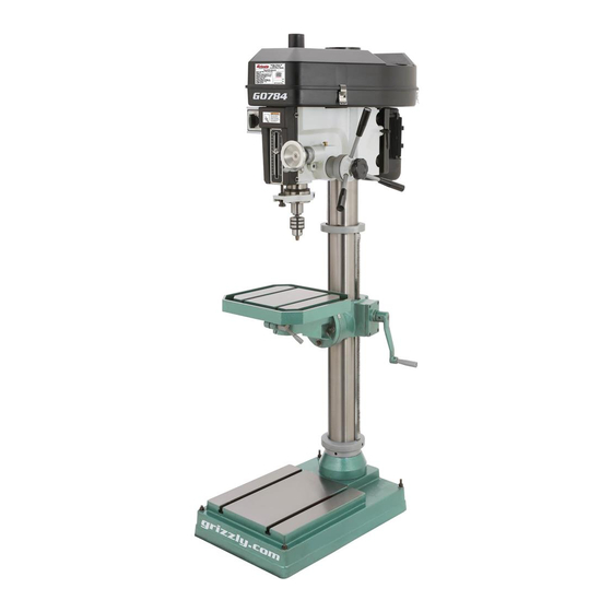
MODEL G0784
15" HEAVY-DUTY
FLOOR DRILL PRESS
OWNER'S MANUAL
(For models manufactured since 03/15)
COPYRIGHT © APRIL, 2015 BY GRIZZLY INDUSTRIAL, INC.
WARNING: NO PORTION OF THIS MANUAL MAY BE REPRODUCED IN ANY SHAPE
OR FORM WITHOUT THE WRITTEN APPROVAL OF GRIZZLY INDUSTRIAL, INC.
#WKBLMN17372 PRINTED IN CHINA
V1.04.15
Advertisement
Table of Contents

Related Manuals for Grizzly G0784


Summary of Contents for Grizzly G0784
- Page 1 (For models manufactured since 03/15) COPYRIGHT © APRIL, 2015 BY GRIZZLY INDUSTRIAL, INC. WARNING: NO PORTION OF THIS MANUAL MAY BE REPRODUCED IN ANY SHAPE OR FORM WITHOUT THE WRITTEN APPROVAL OF GRIZZLY INDUSTRIAL, INC. #WKBLMN17372 PRINTED IN CHINA V1.04.15...
- Page 2 This manual provides critical safety instructions on the proper setup, operation, maintenance, and service of this machine/tool. Save this document, refer to it often, and use it to instruct other operators. Failure to read, understand and follow the instructions in this manual may result in fire or serious personal injury—including amputation, electrocution, or death.
-
Page 3: Table Of Contents
Calculating Spindle Speed for Drilling ..20 Changing Spindle Speed ......21 Using Spindle Downfeed Controls ....22 Installing/Removing Tooling ......22 Adjusting Headstock Position ...... 24 Setting Depth Stop ........24 Positioning Table ......... 25 Model G0784 (Mfd. since 03/15) -
Page 4: Introduction
ID label (see below). This information is required for us to provide proper tech support, and it helps us determine if updated documenta- tion is available for your machine. Manufacture Date Serial Number Model G0784 (Mfd. since 03/15) -
Page 5: Identification
E. Belt Cover P. Motor Locking Lever Fine Downfeed Handwheel Q. Coarse Downfeed Lever G. Table R. Column H. Pivot Lock Handle S. Rack Chuck Table Elevation Crank Spindle U. Base K. Depth Stop Adjustment Knob Model G0784 (Mfd. since 03/15) -
Page 6: Controls & Components
When tightened, locks motor in position to maintain belt ten- Pivot Lock Handle: Allows table to rotate sion. freely when loosened. M. Table Elevation Crank: Changes elevation of table assembly. Model G0784 (Mfd. since 03/15) -
Page 7: Machine Data Sheet
MACHINE DATA SHEET Customer Service #: (570) 546-9663 · To Order Call: (800) 523-4777 · Fax #: (800) 438-5901 MODEL G0784 15" HEAVY‐DUTY FLOOR DRILL PRESS Product Dimensions: Weight................................662 lbs. Width (side-to-side) x Depth (front-to-back) x Height..............23 x 35-1/2 x 67 in. - Page 8 The information contained herein is deemed accurate as of 4/9/2017 and represents our most recent product specifications. Model G0784 PAGE 2 OF 2 Due to our ongoing improvement efforts, this information may not accurately describe items previously purchased. Model G0784 (Mfd. since 03/15)
-
Page 9: Section 1: Safety
Everyday ery. Never operate under the influence of drugs or eyeglasses are NOT approved safety glasses. alcohol, when tired, or when distracted. Model G0784 (Mfd. since 03/15) - Page 10 EXPERIENCING DIFFICULTIES. If at any time debris. Make sure they are properly installed, you experience difficulties performing the intend- undamaged, and working correctly BEFORE ed operation, stop using the machine! Contact our operating machine. Technical Support at (570) 546-9663. Model G0784 (Mfd. since 03/15)
-
Page 11: Additional Safety For Drill Presses
If normal safety pre- Failure to do so could result in serious per- cautions are overlooked or ignored, serious sonal injury, damage to equipment, or poor personal injury may occur. work results. Model G0784 (Mfd. since 03/15) -
Page 12: Section 2: Power Supply
To reduce the risk of these hazards, avoid over- loading the machine during operation and make sure it is connected to a power supply circuit that meets the specified circuit requirements. -10- Model G0784 (Mfd. since 03/15) -
Page 13: Grounding Instructions
-11- Model G0784 (Mfd. since 03/15) -
Page 14: Section 3: Setup
Grizzly or the shipping agent. You MUST have the original pack- Box 1 (Figure 5) aging to file a freight claim. -
Page 15: Cleanup
Figure 6. T23692 Orange Power Degreaser. off the rest with the rag. Repeat Steps 2–3 as necessary until clean, then coat all unpainted surfaces with a quality metal protectant to prevent rust. -13- Model G0784 (Mfd. since 03/15) -
Page 16: Site Considerations
Only install in an Shadows, glare, or strobe effects that may distract access restricted location. or impede the operator must be eliminated. ⁄ " 23" 30" Minimum for Maintenance Figure 7. Minimum working clearances. -14- Model G0784 (Mfd. since 03/15) -
Page 17: Lifting & Placing
With another person to help to steady machine, lift it just enough to clear pallet and any floor obstacles, then place it in its final position on shop floor. -15- Model G0784 (Mfd. since 03/15) -
Page 18: Joining Drill Chuck & Arbor
Refer to Extension Cords on Page 11 for more infor- mation. Figure 10. Joining drill chuck and arbor. Attempt to separate drill chuck and arbor by hand —if they separate, repeat Steps 3–4. -16- Model G0784 (Mfd. since 03/15) -
Page 19: Test Run
DO NOT start machine until all preceding setup instructions have been performed. Operating an improperly set up machine may result in malfunction or unexpect- ed results that can lead to serious injury, death, or machine/property damage. -17- Model G0784 (Mfd. since 03/15) -
Page 20: Spindle Break-In
DO NOT perform this procedure indepen- dently of the Test Run section. The drill press could be seriously damaged if the controls are set differently than instructed in that section. -18- Model G0784 (Mfd. since 03/15) -
Page 21: Section 4: Operations
V-belt configuration chart located inside ects. Regardless of the content in this sec- belt cover. tion, Grizzly Industrial will not be held liable for accidents caused by lack of training. Connects machine to power, and starts spin- dle rotation in proper direction for cutting tool installed. -
Page 22: Calculating Spindle Speed For Drilling
Aluminum Mild Steel Carbide Insert Type One-Piece Type 1800 Tenon/Plug Cutters Soft Wood Hard Wood Plastic Brass Aluminum Mild Steel 3/8" – 1/2" 1200 1000 5/8" – 1" Figure 11. Drill bit speed chart. -20- Model G0784 (Mfd. since 03/15) -
Page 23: Changing Spindle Speed
Tip: Lower headstock for easy access (see Headstock Position on Page 24). The Model G0784 is capable of twelve different spindle speed RPMs. Spindle speed is controlled by the configuration of V-belts and pulleys located inside the belt cover on top of the machine. -
Page 24: Using Spindle Downfeed Controls
Installing/Removing Downfeed Controls Tooling This machine has coarse downfeed levers and a The Model G0784 includes the following spindle fine downfeed handwheel. tools (see Figure 16): To operate the downfeed levers, simply pull for- A. Drill Chuck w/R-8 Arbor: Use with drill bits. -
Page 25: Installing Tooling
Figure 17. Threading drawbar into collet/arbor to Figure 18. Tapping top of drawbar with drawbar install tooling. nut already loosened to remove tooling. Unthread drawbar until it is free from tooling. Remove tooling from spindle when not in use. -23- Model G0784 (Mfd. since 03/15) -
Page 26: Adjusting Headstock Position
20) to move head up or down as desired. Use your hands to rotate headstock on column as needed. Indicator Knurled Knob Figure 21. Depth stop controls. Headstock Elevation Crank Figure 20. Location of headstock elevation crank. Retighten headstock lock nuts. -24- Model G0784 (Mfd. since 03/15) -
Page 27: Positioning Table
Remove any loose objects from table surface. Retighten tilt-lock nuts. Loosen table lock handles shown in Figure 22. 3. Adjust table height by rotating table elevation crank (see Figure 22), then re-tighten table lock handles. -25- Model G0784 (Mfd. since 03/15) -
Page 28: Section 5: Accessories
Made for ⁄ " T-slots. To reduce this risk, only install accessories recommended for this machine by Grizzly. NOTICE Refer to our website or latest catalog for additional recommended accessories. G5753— 6" Cast-Iron Drill Press Vise If you use a drill press and value your fingers, you Figure 25. - Page 29 T26685 T26934 Figure 30. T26685 Moly-D Oil-ISO 32 and T23964 Armor Plate with Moly-D Grease Figure 28. T26688 R-8 Quick Change Collet 8 pc. Set www.grizzly.com 1-800-523-4777 order online at or call -27- Model G0784 (Mfd. since 03/15)
-
Page 30: Section 6: Maintenance
, or Boeshield T-9 (see ® ® • Make sure drill is clean and lubricated. Figure 31 and the Grizzly catalog or website). • Check for worn or damaged wires. • Check for any other unsafe condition. • Check belts for tension and wear. -
Page 31: Lubrication
Figure 33. Belt tension. Figure 32. Location of oil cup. NOTICE Follow reasonable lubrication practices as outlined in this manual. Failure to do so could lead to premature failure of your machine and will void the warranty. -29- Model G0784 (Mfd. since 03/15) -
Page 32: Section 7: Service
7. Test by rotating shaft; rotational grinding/loose shaft requires bearing replacement. 8. Chuck unbalanced or cutter dull. 8. Replace chuck; replace/resharpen cutter. 9. Centrifugal switch out of adjustment or at 9. Adjust or replace. fault. -30- Model G0784 (Mfd. since 03/15) - Page 33 1. Increase return spring tension (Page 32). return to highest 2. Worn return spring. 2. Replace return spring. position. 1. Calibrate depth stop (Page 32). Depth stop pro- 1. Depth stop not calibrated. ducing inaccurate results. -31- Model G0784 (Mfd. since 03/15)
-
Page 34: Tensioning Return Spring
35) out enough so notches just clear roll pin. HOLD SPRING COVER TIGHTLY during this step, or force of spring will cause cover to spin out of your hands. Figure 36. Calibrating depth stop. -32- Model G0784 (Mfd. since 03/15) -
Page 35: Section 8: Wiring
Technical Support at (570) 546-9663. The photos and diagrams included in this section are best viewed in color. You can view these pages in color at www.grizzly.com. READ ELECTRICAL SAFETY -33- Model G0784 (Mfd. Since 03/15) ON PAGE 33! -
Page 36: Electrical Components
Junction Figure 38. Switch box wiring (right side). Motor Figure 37. Electrical component wiring overview. Figure 39. Switch box wiring (left side). Figure 40. Motor junction box wiring. READ ELECTRICAL SAFETY -34- Model G0784 (Mfd. Since 03/15) ON PAGE 33! -
Page 37: Wiring Diagram
220V Motor Start Capacitor Capacitor 150 MFD 20 MFD 250 VAC 450 VAC U2 V1 6-15 Plug (As Recommended) Ground Ground Spindle Switch Left Right Side Side Ground READ ELECTRICAL SAFETY -35- Model G0784 (Mfd. Since 03/15) ON PAGE 33! -
Page 38: Section 9: Parts
SECTION 9: PARTS Main Breakdown 98-1 98-3 98-7 98-4 98-2 98-8 98-9 98-6 98-5 63 64 22 23 -36- Model G0784 (Mfd. since 03/15) -
Page 39: Main Parts List
98-6 P0784098-6 CETRIFUGAL SWITCH 48 P0784048 QUILL WORM SHAFT 98-7 P0784098-7 MOTOR JUNCTION BOX 49 P0784049 BALL BEARING 6202ZZ 98-8 P0784098-8 BALL BEARING 6205Z (FRONT) 50 P0784050 SPACER 29MM 98-9 P0784098-9 BALL BEARING 6205Z (REAR) -37- Model G0784 (Mfd. since 03/15) - Page 40 105 P0784105 HELICAL GEAR 15T 114 P0784114 ROTARY SWITCH CANSEN LW5D-16 106 P0784106 EXT RETAINING RING 14MM 115 P0784115 CAP SCREW M4-.7 X 6 107 P0784107 ELEVATION CRANK 116 P0784116 POWER CORD 14G 3W 72" -38- Model G0784 (Mfd. since 03/15)
-
Page 41: Base Breakdown
Base Breakdown -39- Model G0784 (Mfd. since 03/15) -
Page 42: Base Parts List
Please Note: We do our best to stock replacement parts whenever possible, but we cannot guarantee that all parts shown here are available for purchase. Call (800) 523-4777 or visit our online parts store at www.grizzly.com to check for availability. -
Page 43: Accessories
P0784313 SPINDLE SLEEVE R-8 X MT#3 P0784306 HEX WRENCH 4MM P0784314 DRILL CHUCK ARBOR R8 X B16 P0784307 HEX WRENCH 3MM P0784315 DRILL CHUCK B16 1-13MM P0784308 T-BOLT M14-2 X 55 P0784316 DRILL CHUCK KEY 8MM STD 11 SD-16MM -41- Model G0784 (Mfd. since 03/15) -
Page 44: Labels & Cosmetics
DO NOT REPRODUCE OR CHANGE THIS ARTWORK alcohol. COLOR CODES WITHOUT WRITTEN APPROVAL! Grizzly will not accept labels changed without approval. 14. Do not expose to rain or use in wet locations. COLOR CODES artwork changes are required, contact us immediately at manuals@grizzly.com. -
Page 45: Warranty Card
Would you recommend Grizzly Industrial to a friend? _____ Yes _____No Would you allow us to use your name as a reference for Grizzly customers in your area? Note: We never use names more than 3 times. _____ Yes _____No 10. - Page 46 FOLD ALONG DOTTED LINE Place Stamp Here GRIZZLY INDUSTRIAL, INC. P.O. BOX 2069 BELLINGHAM, WA 98227-2069 FOLD ALONG DOTTED LINE Send a Grizzly Catalog to a friend: Name_______________________________ Street_______________________________ City______________State______Zip______ TAPE ALONG EDGES--PLEASE DO NOT STAPLE...
-
Page 47: Warranty & Returns
WARRANTY & RETURNS Grizzly Industrial, Inc. warrants every product it sells for a period of 1 year to the original purchaser from the date of purchase. This warranty does not apply to defects due directly or indirectly to misuse, abuse, negligence, accidents, repairs or alterations or lack of maintenance.