Table of Contents
Advertisement
Quick Links
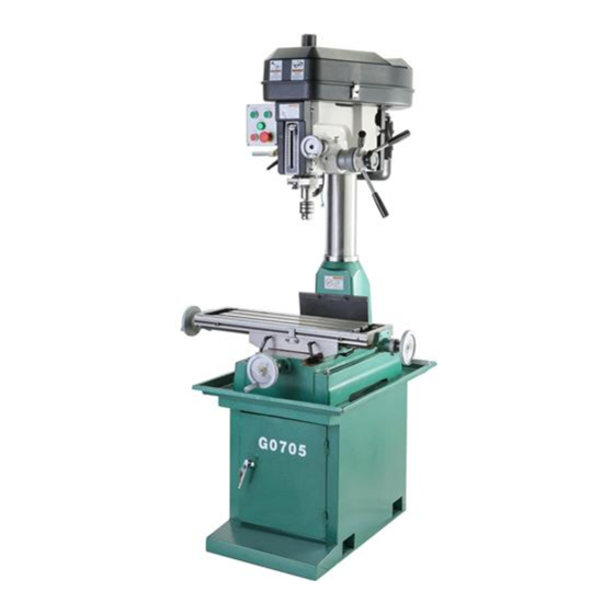
The Model G0760 is the same machine as the Model G0705 except the Model G0760 has an X-axis table
power feed. Except for the differences noted in this insert, all other content in the Model G0705 owner's
manual applies to this machine. Before operating your new machine, you MUST read and understand this
insert and the entire Model G0705 manual to reduce the risk of injury when using this machine.
If you have any further questions about this manual insert or the differences between the Model G0760
and the Model G0705, contact our Technical Support at (570) 546-9663 or email techsupport@grizzly.com.
Power Feed Assembly
248
248-2
248-4
248-3
409
REF PART #
DESCRIPTION
248
P0760248
POWER FEED ASSY ALIGN AS-235
248-1 P0760248-1
MOUNTING BRACKET 2-PC
248-2 P0760248-2
CONTROL HANDLE
248-3 P0760248-3
SPEED CONTROL KNOB
248-4 P0760248-4
ON/OFF SWITCH
248-5 P0760248-5
ZYTEL GEAR ASSEMBLY
248-6 P0760248-6
CAP SCREW M8-1.25 X 20
248-7 P0760248-7
DOWEL PIN 6 X 30
401
P0760401
MACHINE ID LABEL
409
P0760409
MODEL NUMBER LABEL
WARNING: NO PORTION OF THIS MANUAL MAY BE REPRODUCED IN ANY SHAPE
OR FORM WITHOUT THE WRITTEN APPROVAL OF GRIZZLY INDUSTRIAL, INC.
(FOR MODELS MANUFACTURED SINCE 12/13) #TS16257 PRINTED IN CHINA
248-1
248-7
248-6
248-5
401
COPYRIGHT © JANUARY, 2014 BY GRIZZLY INDUSTRIAL, INC.
MODEL G0760
8" X 29" MILL/DRILL
w/STAND & POWER FEED
MANUAL INSERT
Attaching Power Feed
For shipping purposes, the power feed assembly
comes unattached from the table.
To attach power feed assembly:
1.
DISCONNECT MACHINE FROM POWER!
2.
Insert pins shown in Figure 1 into holes on
top of left side of table.
Figure 1. Power feed assembly attached to
3.
Using a 6mm hex wrench, secure assem-
bly with two M8-1.25 x 20 cap screws (see
Figure 1).
Pins
Cap Screws
table.
Advertisement
Table of Contents

Related Manuals for Grizzly G0760


Summary of Contents for Grizzly G0760
- Page 1 & POWER FEED MANUAL INSERT The Model G0760 is the same machine as the Model G0705 except the Model G0760 has an X-axis table power feed. Except for the differences noted in this insert, all other content in the Model G0705 owner's manual applies to this machine.
- Page 2 C. Rapid Switch. When held down, moves table rapidly in the direction chosen. D. Power Light. Illuminates when unit is con- nected to power. E. Speed Dial. Controls rate of power feed. ON/OFF Switch. Turns power feed ON and OFF. Model G0760 (Mfd. Since 12/13)
- Page 3 Copyright © MarCh, 2010 By grizzly industrial, inC. revised april, 2013 (tr) Warning: no portion of this manual may be reproduced in any shape or form Without the Written approval of grizzly industrial, inc.
- Page 4 This manual provides critical safety instructions on the proper setup, operation, maintenance, and service of this machine/tool. Save this document, refer to it often, and use it to instruct other operators. Failure to read, understand and follow the instructions in this manual may result in fire or serious personal injury—including amputation, electrocution, or death.
-
Page 5: Table Of Contents
table of contents introduction ..........2 section 5: accessories ......36 Manual accuracy ........... 2 section 6: maintenance ......38 Contact info............ 2 schedule ............38 Machine description ........2 Cleaning and protecting ......38 identification ........... 3 lubrication ........... 39 section 1: safety ........ -
Page 6: Introduction
Any updates to your model tionary on the table while the cutting tool is fed of machine will be reflected in these documents vertically into the workpiece with the movement of as soon as they are complete. -
Page 7: Identification
identification detail of left side of machine figure 1. Model g0705 identification. a. Control panel m. longitudinal travel lock b. drawbar & Cap n. Cabinet stand c. Belt Cover o. Mounting Bolt hole d. Motor p. Cabinet door e. Coarse downfeed lever Q. - Page 8 MACHINE DATA SHEET Customer Service #: (570) 546-9663 · To Order Call: (800) 523-4777 · Fax #: (800) 438-5901 MODEL G0705 DRILL/MILL WITH STAND 29 INCH X 8 INCH TABLE Product Dimensions: Weight................................617 lbs. Width (side-to-side) x Depth (front-to-back) x Height............41-5/8 x 40-1/2 x 43-1/4 in. Footprint (Length x Width).......................
- Page 9 Main Specifications: Operation Info Spindle Travel............................ 4-11/16 in. Max Distance Spindle to Column......................7-3/4 in. Max Distance Spindle to Table......................17-5/16 in. Longitudinal Table Travel (X-Axis)....................19-11/16 in. Cross Table Travel (Y-Axis)........................7-1/2 in. Drilling Capacity for Cast Iron......................1-3/16 in. Drilling Capacity for Steel..........................
- Page 10 Accessories Included: Drill chuck 1/16-1/2 in. with MT#3 spindle taper Tool box Chuck key Drift Oil bottle Hex wrenches Locking nuts for leveling feet R8 to MT#3 adapter MT#3 to MT#2 adapter Two T-bolts The information contained herein is deemed accurate as of 8/15/2013 and represents our most recent product specifications. Model G0705 PAGE 3 OF 3 Due to our ongoing improvement efforts, this information may not accurately describe items previously purchased.
-
Page 11: Section 1: Safety
section 1: safety for your own safety, read instruction manual before operating this machine the purpose of safety symbols is to attract your attention to possible hazardous conditions. this manual uses a series of symbols and signal words intended to convey the level of impor- tance of the safety messages. - Page 12 Wearing proper apparel. do not wear forcing machinery. do not force machine. clothing, apparel or jewelry that can become it will do the job safer and better at the rate for entangled in moving parts. always tie back or which it was designed. cover long hair.
-
Page 13: Additional Safety For Mill/Drills
additional safety for mill/drills understanding controls. Make sure you machine care and maintenance. never understand the use and operation of all controls. operate the mill/drill with damaged or worn parts. Maintain your mill/drill in proper working condition. safety accessories. always use a chip perform routine inspections and maintenance guard in addition to your safety glasses when mill-... -
Page 14: Section 2: Power Supply
section 2: poWer supply availability circuit information Before installing the machine, consider the avail- A power supply circuit includes all electrical ability and proximity of the required power supply equipment between the breaker box or fuse panel circuit. If an existing circuit does not meet the in the building and the machine. -
Page 15: Grounding Requirements
grounding requirements This machine MUST be grounded. In the event of certain malfunctions or breakdowns, grounding Serious injury could occur if you connect reduces the risk of electric shock by providing a the machine to power before completing the path of least resistance for electric current. setup process. -
Page 16: Conversion
Indicator Light Type XDJ2(J) 220V AC Indicator Light Type XDJ2(J) 110V AC cedure you need help, call grizzly tech support To Plug (Indicator is wired the same for 110V/220V) at (570) 546-9663. - Page 17 4. Remove the screws that secure the brass 10. Locate the terminal block located in the motor junction box, shown in Figure 8. contactor mounting plate to the back of the electrical box, then pull the contactors out to access the gray tab shown in Figure 7. Pull outward on the gray tab to release each Motor 220V contactor from the mounting plate. Terminal Block 110V Terminal Block Jumper...
- Page 18 11. use a phillips screwdriver to remove the 14. install a neMa 5-20 plug such as the one screws that secure the two metal jumpers shown in figure 3 onto the power cord, as to the terminal block, as shown in figure 9, illustrated in figure 10.
-
Page 19: Section 3: Setup
section 3: setup needed for setup this machine presents serious injury hazards the following are needed to complete the setup to untrained users. read process: through this entire manu- al to become familiar with description the controls and opera- • precision level ........... -
Page 20: Inventory
inventory The following is a list of items shipped with your machine. Before beginning setup, lay these items out and inventory them. If any non-proprietary parts are missing (e.g. a nut or a washer), we will gladly replace them; or for the sake of expediency, replacements can be obtained at your local hardware store. -
Page 21: Cleanup
cleanup gasoline and petroleum products have low flash the unpainted surfaces of your machine are points and can explode coated with a heavy-duty rust preventative that or cause fire if used to prevents corrosion during shipment and storage. clean machinery. avo i d this rust preventative works extremely well, but it u sing t h e s e p r o du c t s will take a little time to clean. -
Page 22: Site Considerations
site considerations Weight Load Physical Environment Refer to the Machine Data Sheet for the weight The physical environment where the machine is of your machine. Make sure that the surface upon operated is important for safe operation and lon- which the machine is placed will bear the weight gevity of machine components. -
Page 23: Mounting Options
& placing g7158—1-1/2" dia., 800 lb capacity machine on page 22. Mount the machine g7159—3"... -
Page 24: Using Machine Mounts
using machine mounts anchoring to concrete floors anchoring machinery to the floor prevents tipping using machine mounts, shown in figure 16, gives or shifting and reduces vibration that may occur the advantage of fast leveling and vibration reduc- during operation, resulting in a machine that runs tion. -
Page 25: Mounting To A Workbench
assembly mounting to a Workbench if you are placing the machine on an existing workbench, it must be securely attached to the workbench. assembly of the Model g0705 consists of attach- ing the three handwheel handles to the machine. the base of this machine has mounting holes that allow it to be fastened to a workbench or to assemble your machine: other mounting surface to prevent it from moving... -
Page 26: Moving & Placing Machine
moving & placing unbolt the machine from the pallet, then with an assistant steadying the machine to pre- machine vent it from swinging, lift it slightly off of the pallet. use the cross handwheel to move the table forward or backward as necessary to balance the machine so it hangs as close to to move your machine into position: level as possible. -
Page 27: Test Run
test run push the eMergenCy stop button in, then twist it clockwise (see figure 22) so it pops out. When the eMergenCy stop button pops out, the switch is reset and ready once the assembly is complete, test run your for operation. -
Page 28: Break-In
break-in press the stop button to stop the machine. allow the spindle to stop rotating before pro- ceeding. repeat step 5 with the reverse button. NOTICE the spindle should rotate in the opposite direction. failure to follow spindle break-in proce- dures will likely cause rapid deterioration of press the eMergenCy stop button to the spindle and other related parts and may... -
Page 29: Section 4: Operations
Wears safety glasses or a face shield. regardless of the content in this section, grizzly industrial will not be held liable for accidents caused by lack of training. -25- Model G0705 (Mfg. since 09/09) -
Page 30: Basic Controls
basic controls For milling operations, loosens the quill lock lever and uses the quill feed lever or the fine feed knob to set the cutting tool height according to the workpiece. then, presses use the descriptions and figures below to become the ForWard or reverse button to start familiar with the basic controls of your machine. - Page 31 longitudinal travel handwheels: Control longi- head crank: Changes the elevation of the entire tudinal (X-axis) travel of the table. headstock. cross travel handwheel: Controls cross (y-axis) travel of the table. table locks: lock the table in position along their respective axes. travel stops: limit longitudinal table travel.
-
Page 32: Calculating Spindle Speed For Milling
calculating spindle the cutting speeds shown in figure 29 do not represent the recommended spindle speed in speed for milling rpM. the relationship between cutting speed and spindle rpM is dependent on the diameter of the installed cutting tool. When a tool's cutting edge rotates, as is the case with a milling machine, Before calculating the spindle speed for a milling the cutting speed of that tool is directly propor-... -
Page 33: Speed Changes
speed changes open the belt cover, then loosen the two idler cap screws (figure 31) that hold the idler pul- ley in place so it can move freely. the Model g0705 is capable of twelve different speed settings. different types of cuts and materi- als require varying speeds. -
Page 34: Calculating Spindle Speed For Drilling
calculating spindle speed for drilling using the drill bit speed chart lubrication suggestions the chart shown in figure 33 is intended as Wood ............none a guide only. always follow the manufacturer's plastics ..........soapy Water speed recommendations if provided with your Brass .......Water-Based lubricant drill bits, cutters, or hole saws. -
Page 35: Spindle Height
spindle height loosen the thumb screw on the rim surface of the handwheel dial. turn the dial until the "0" lines up with the index line. tighten the thumb screw. the Model g0705 has coarse downfeed levers and a micro-adjustment handwheel. to operate turn the handwheel according to the distance the downfeed levers, simply pull forward and you want to move the quill downward. -
Page 36: Loading Tooling
loading tooling if you're using a collet, insert the cutter in the hole at the bottom of the collet. Be sure to protect your hands from the cutter with leather gloves or a shop rag. the Model g0705 features an r-8 spindle that accepts r-8 collets and arbors. -
Page 37: Drill Chuck Arbor
drill chuck arbor collet adapters your machine includes an r-8 drill chuck arbor the Model g0705 includes two adapters that will and Mt#3 drill chuck. Before use, the drill chuck allow the use of Mt#3 and Mt#2 tooling. a drift must be installed onto the arbor. -
Page 38: Headstock Position
depth stop headstock position the depth stop is used to limit the range of down- the headstock height and rotation on the Model ward movement by the drill bit or cutter. Maximum g0705 can be adjusted for various applications. depth is 4 ⁄... -
Page 39: Graduated Dials
table travel cross feed the cross handwheel shown in figure 42 move the table along the cross axis (y-axis). one complete revolution of the handwheel moves the the mill/drill table moves in the longitudinal cross slide 0.100". the table lock lever located (X-axis) and cross (y-axis) directions. -
Page 40: Section 5: Accessories
10 second vernier scales, gear drives with oil immersion and satin chrome dials. see the current grizzly catalog for full specifica- tions. Features: 4.330" overall height (horizontal), 6.750" height to center hole (vertical), #3 Morse taper, 0.465"... - Page 41 g2861—face mill g5641—1-2-3 blocks g4051—carbide insert for face mill g9815—parallel set this 2 " Face Mill accepts four carbide inserts h5556—edge finder set (not included). Comes with an r-8 arbor. g5641 h5556 g9815 figure 49. g2861 Face Mill. figure 52. g5641 1-2-3 Blocks, g9815 parallel g9760—20-pc.
-
Page 42: Section 6: Maintenance
, or Boeshield t-9 (see the ® ® • Check for worn or damaged wires. grizzly catalog or website). • Check for any other unsafe condition. monthly check: • Check that gibs are adjusted properly. biannual check: •... -
Page 43: Lubrication
lubrication table leadscrews every six months, or more frequently under heavy use, clean and lubricate the leadscrews. points requiring periodic lubrication are: items needed: Mobil vactra 2 or iso 68 equivalent ....1 a. column. a light film of oil (Mobil vactra 2 or stiff-Bristled nylon Brush for Cleaning .... - Page 44 v-belts using the longitudinal handwheel, move the table as far to one side as possible. use mineral spirits and a brush to clean as inspect regularly for tension and wear. refer to much of the oil and debris as possible off of figure 57 for proper belt tension.
-
Page 45: Section 7: Service
troubleshooting section 7: service review the troubleshooting and procedures in this section to fix or adjust your machine if a problem devel- ops. if you need replacement parts or you are unsure of your repair skills, then feel free to call our technical support at (570) 546-9663. - Page 46 symptom possible Cause possible solution tool slips in collet. 1. Collet is not fully drawn up into 1. tighten drawbar. spindle taper. 2. Wrong size collet. 2. Measure tool shank diameter and match with appropriate diameter collet. 3. debris on collet or in spindle taper. 3.
-
Page 47: Gibs
gibs return spring gibs are wedge-shaped pieces of metal that fill the gap between the dovetailed ways of the machine. By adjusting the position of the gib in the gap, you the tail end of the spring is located on can remove any play that might exist between the the perimeter of the spring housing. -
Page 48: Leadscrew Backlash
tools needed put on gloves and pull the spring cover out 3mm hex Bit ............1 enough so the notches just clear the roll pin. hold the spring Cover tightly or 6" extension for hex Bit ........1 the force of the spring will spin it out of your ratchet for hex Bit .......... -
Page 49: Section 8: Wiring
Technical source. Support at (570) 546-9663. The photos and diagrams included in this section are best viewed in color. You can view these pages in color at www.grizzly.com. -45- Model G0705 (Mfg. since 09/09) -
Page 50: G0705 Wiring Diagram
g0705 Wiring diagram Motor 220V 110V Terminal Block Jumper To Electrical Box Position. (Wire positions are the same for 110V/220V) Start Capacitor Capacitor 20 MFD 150 MFD 450 VAC 250 VAC Ground To Electrical Box Cord Rewired for 110V Ground Neutral 110 VAC 5-20 Plug... - Page 51 g0705 Wiring diagram (continued) Contactor Information For 220V, Contactor Type 3TB41 22-OX, Coil Voltage 220V/60Hz/1PH, SIEMENS For 110V, Contactor Type 3TB41 22-OX, Coil Voltage 110V/60Hz/1PH, SIEMENS (Contactor is wired the same for 110V/220V) 13NO 14NO 21NC 22NC 31NC 32NC To Motor 43NO 44NO 13NO...
-
Page 52: Section 9: Parts
section 9: parts headstock parts breakdown -48- Model G0705 (Mfg. since 09/09) -
Page 53: Headstock Parts List
headstock parts list REF PART # DESCRIPTION REF PART # DESCRIPTION P0705001 HEAD CASTING P0705020 PINION SHAFT P0705002 DRAWBAR PFH08 FLAT HD SCR 10-24 X 1/2 P0705003 SPINDLE LOCK NUT PK25M KEY 7 X 7 X 20 P0705004 SPINDLE PULLEY P0705023 DOWNFEED ASSEMBLY P0705005... - Page 54 headstock parts list (continued) REF PART # DESCRIPTION REF PART # DESCRIPTION PCAP05 CAP SCREW 1/4-20 X 3/4 P0705080 PULLEY IDLER PLATE P0705049 ELEVATION CRANK PN04 HEX NUT 5/8-11 P0705051 CLAMP HANDLE PW07 FLAT WASHER 5/16 P0705052 OUTER QUILL CLAMP PCAP08 CAP SCREW 5/16-18 X 1-1/2 P0705053...
-
Page 55: Base Parts Breakdown
base parts breakdown -51- Model G0705 (Mfg. since 09/09) -
Page 56: Base Parts List
base parts list REF PART # DESCRIPTION REF PART # DESCRIPTION P0705201 TABLE PB09 HEX BOLT 5/16-18 X 1/2 P0705202 T-NUT 1/4-20 P0705227 GIB SCREW P0705203 TABLE STOP P0705228 LOCK HANDLE SPACER PCAP04 CAP SCREW 1/4-20 X 1/2 P0705229 LOCK HANDLE M8-1.25 X 32 PLUBE001 TAP-IN BALL OILER 8MM P0705229... -
Page 57: Electrical Components Breakdown & List
electrical components breakdown & list 13NO 14NO 21NC 22NC 31NC 32NC 43NO 44NO 13NO 14NO 21NC 22NC 31NC 32NC 43NO 44NO Electrical Box Control Panel (Viewed From Behind) 13NO 14NO 21NC 22NC 31NC 32NC 43NO 44NO FORWARD REVERSE BUTTON BUTTON 13NO 14NO POWER... -
Page 58: Labels Breakdown And List
(800) 523-4777 or www.grizzly.com to order new labels. -54-... - Page 59 Would you recommend Grizzly Industrial to a friend? _____ Yes _____No Would you allow us to use your name as a reference for Grizzly customers in your area? Note: We never use names more than 3 times. _____ Yes _____No 10.
- Page 60 FOLD ALONG DOTTED LINE Place Stamp Here GRIZZLY INDUSTRIAL, INC. P.O. BOX 2069 BELLINGHAM, WA 98227-2069 FOLD ALONG DOTTED LINE Send a Grizzly Catalog to a friend: Name_______________________________ Street_______________________________ City______________State______Zip______ TAPE ALONG EDGES--PLEASE DO NOT STAPLE...
-
Page 61: Warranty And Returns
WARRANTY AND RETURNS Grizzly Industrial, Inc. warrants every product it sells for a period of 1 year to the original purchaser from the date of purchase. This warranty does not apply to defects due directly or indirectly to misuse, abuse, negligence, accidents, repairs or alterations or lack of maintenance.