Table of Contents
Advertisement
Quick Links
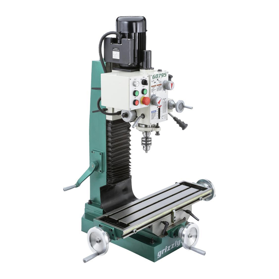
MODEL G0795
HEAVY-DUTY BENCHTOP
MILL/DRILL
OWNER'S MANUAL
(For models manufactured since 02/15)
COPYRIGHT © JULY, 2015 BY GRIZZLY INDUSTRIAL, INC., REVISED AUGUST, 2015 (JH)
WARNING: NO PORTION OF THIS MANUAL MAY BE REPRODUCED IN ANY SHAPE
OR FORM WITHOUT THE WRITTEN APPROVAL OF GRIZZLY INDUSTRIAL, INC.
#JH17427 PRINTED IN CHINA
V1.08.15
Advertisement
Table of Contents

Related Manuals for Grizzly G0795


Summary of Contents for Grizzly G0795
- Page 1 OWNER'S MANUAL (For models manufactured since 02/15) COPYRIGHT © JULY, 2015 BY GRIZZLY INDUSTRIAL, INC., REVISED AUGUST, 2015 (JH) WARNING: NO PORTION OF THIS MANUAL MAY BE REPRODUCED IN ANY SHAPE OR FORM WITHOUT THE WRITTEN APPROVAL OF GRIZZLY INDUSTRIAL, INC.
- Page 2 This manual provides critical safety instructions on the proper setup, operation, maintenance, and service of this machine/tool. Save this document, refer to it often, and use it to instruct other operators. Failure to read, understand and follow the instructions in this manual may result in fire or serious personal injury—including amputation, electrocution, or death.
-
Page 3: Table Of Contents
Table of Contents INTRODUCTION ..........2 SECTION 5: ACCESSORIES ......28 Contact Info............ 2 SECTION 6: MAINTENANCE ......33 Manual Accuracy ........... 2 Schedule ............33 Identification ........... 3 Cleaning & Protecting ........33 Controls & Components ......... 4 Lubrication ........... 34 SECTION 1: SAFETY ........ -
Page 4: Introduction
ID label (see below). This information is required for us to provide proper tech support, and it helps us determine if updated documenta- tion is available for your machine. Manufacture Date Serial Number Model G0795 (Mfd. Since 02/15) -
Page 5: Identification
Downfeed Selector Depth Stop Knob & Scale Coarse Downfeed Work Table Handle Stop X-Axis Table Locks Y-Axis Work Table Handwheel Stop To reduce your risk of serious injury, read this entire manual BEFORE using machine. Model G0795 (Mfd. Since 02/15) -
Page 6: Controls & Components
M. Headstock Elevation Crank Handle: Moves headstock up and down for proper spindle position during setup. N. Spindle Direction Buttons: Controls spindle direction of rotation (as viewed from above). The spindle must be completely stopped before either button is pushed. Model G0795 (Mfd. Since 02/15) -
Page 7: Machine Data
MACHINE DATA SHEET Customer Service #: (570) 546-9663 · To Order Call: (800) 523-4777 · Fax #: (800) 438-5901 MODEL G0795 HEAVY DUTY BENCHTOP MILL/DRILL Product Dimensions: Weight................................408 lbs. Width (side-to-side) x Depth (front-to-back) x Height............... 39 x 30-1/2 x 49-1/2 in. - Page 8 The information contained herein is deemed accurate as of 8/13/2015 and represents our most recent product specifications. Model G0795 PAGE 2 OF 3 Due to our ongoing improvement efforts, this information may not accurately describe items previously purchased. Model G0795 (Mfd. Since 02/15)
-
Page 9: Section 1: Safety
Everyday ery. Never operate under the influence of drugs or eyeglasses are NOT approved safety glasses. alcohol, when tired, or when distracted. Model G0795 (Mfd. Since 02/15) - Page 10 EXPERIENCING DIFFICULTIES. If at any time debris. Make sure they are properly installed, you experience difficulties performing the intend- undamaged, and working correctly BEFORE ed operation, stop using the machine! Contact our operating machine. Technical Support at (570) 546-9663. Model G0795 (Mfd. Since 02/15)
-
Page 11: Additional Safety For Mill/Drills
Use this machine with respect and caution to lessen the possibility of operator injury. If normal safety precautions are over- looked or ignored, serious personal injury may occur. Model G0795 (Mfd. Since 02/15) -
Page 12: Section 2: Power Supply
To reduce the risk of these hazards, avoid over- loading the machine during operation and make sure it is connected to a power supply circuit that meets the requirements in the following section. -10- Model G0795 (Mfd. Since 02/15) -
Page 13: Grounding Instructions
If the plug does not fit the available receptacle, or the machine must be reconnected for use on a different type of circuit, the reconnection must be made by a qualified electrician and comply with all local codes and ordinances. -11- Model G0795 (Mfd. Since 02/15) -
Page 14: Section 3: Setup
L. Spindle Wrench .......... 1 • Wood Block (Page 16) ....... 1 M. Handwheel Handle Assembly (not shown) ..2 To reduce your risk of serious injury, read this entire manual BEFORE using machine. Figure 4. Toolbox inventory. -12- Model G0795 (Mfd. Since 02/15) -
Page 15: Cleanup
Figure 5. T23692 Orange Power Degreaser. off the rest with the rag. Repeat Steps 2–3 as necessary until clean, then coat all unpainted surfaces with a quality metal protectant to prevent rust. -13- Model G0795 (Mfd. Since 02/15) -
Page 16: Site Considerations
Only install in an Shadows, glare, or strobe effects that may distract access restricted location. or impede the operator must be eliminated. Minimum 30" For Maintenance " 39" " Figure 6. Minimum working clearances. -14- Model G0795 (Mfd. Since 02/15) -
Page 17: Lifting & Placing
Sling Lag Screw Flat Washer Machine Base Figure 7. Recommended lifting sling position around headstock. Workbench Secure machine to workbench following instructions in Bench Mounting. Figure 9. Example of a "Direct Mount" setup. -15- Model G0795 (Mfd. Since 02/15) -
Page 18: Assembly
Figure 11. Tapping drill chuck/arbor on block of wood. Attempt to separate drill chuck and arbor by hand —if they separate, repeat Steps 3–4. -16- Model G0795 (Mfd. Since 02/15) -
Page 19: Lubricating Mill/Drill
E-Stop death, or machine/property damage. Button Figure 12. Location of power indicator light and E-Stop button. Rotate mode switch to "Drill". -17- Model G0795 (Mfd. Since 02/15) - Page 20 Press "Off" button and wait for spindle to Continue to the next subsection, Spindle Bearing completely stop. Break-In. Press "Right" button. Spindle should rotate counterclockwise (as viewed from top). 10. Press E-stop button and wait for spindle to completely stop. -18- Model G0795 (Mfd. Since 02/15)
-
Page 21: Spindle Bearing Break-In
To perform spindle break-in procedure: Set mode switch to Drill. Set spindle speed to 115 RPM (see Spindle Speed on Page 26 for details). Run for 10 minutes in each direction of rotation (FWD and REV). -19- Model G0795 (Mfd. Since 02/15) -
Page 22: Section 4: Operations
Read books/magazines or get formal training before beginning any proj- ects. Regardless of the content in this sec- tion, Grizzly Industrial will not be held liable for accidents caused by lack of training. -20- Model G0795 (Mfd. Since 02/15) -
Page 23: Using Spindle Downfeed Controls
(there is no automatic spindle return to the top position, as The Model G0795 is equipped with coarse and with the coarse downfeed controls). This manual fine spindle downfeed controls as shown in level of control makes it easy to precisely lock the Figure 14. -
Page 24: Setting Depth Stop
(or other material) used in the previous step. Remove cardboard and retighten lock Use headstock elevation crank shown in levers. Figure 16 to adjust headstock height. Tighten lock levers to secure setting. -22- Model G0795 (Mfd. Since 02/15) -
Page 25: Controlling Table Travel
Using tilt scale shown in Figure 17 as a guide, push or pull headstock to swivel it into desired position, then retighten the three hex nuts to secure it. Figure 20. Graduated dial on table handwheel. -23- Model G0795 (Mfd. Since 02/15) -
Page 26: Installing/Removing Tooling
X-axis. This feature is typically used when milling up to a The Model G0795 includes a 3–16mm drill chuck shoulder. with an R-8 arbor (see Figure 22). The R-8 arbor is precision-ground, and features a tool slot for easy, secure alignment in the mill/drill spindle. -
Page 27: Removing Tooling
Hold onto tooling with one hand and fully unthread drawbar with the other hand. Tighten drawbar and re-install drawbar cap. Do not overtighten drawbar. Overtightening makes tool removal difficult and may dam- age arbor and threads. -25- Model G0795 (Mfd. Since 02/15) -
Page 28: Setting Spindle Speed
Also, there are a large number of easy-to-use spindle speed calculators that can be found on the internet. These sources will help you take into account the applicable variables in order to deter- mine the best spindle speed for the operation. -26- Model G0795 (Mfd. Since 02/15) -
Page 29: Using Tapping Mode
Set depth stop (see Figure 26) to workpiece hole depth. Mode Switch Downfeed Depth Selector Stop Knob Quill Lock Lever Adjustment Knob Figure 26. Locations of controls for tapping operation. -27- Model G0795 (Mfd. Since 02/15) -
Page 30: Section 5: Accessories
To reduce this risk, only install accessories because they tend to resist run-off and maintain recommended for this machine by Grizzly. their lubricity under a variety of conditions—as well as reduce chatter or slip. Buy in bulk and NOTICE save with 5-gallon quantities. - Page 31 Figure 32. T23964 Armor Plate with Moly-D Multi-Purpose Grease. Figure 34. Model SB1349 South Bend 16-Pc. R-8 Collet Set. www.grizzly.com 1-800-523-4777 order online at or call -29- Model G0795 (Mfd. Since 02/15)
- Page 32 G9806—Dial Indicator 0.05" Range x 0.0001" H3326—Digital Indicator ⁄ " Range x 0.0005" H5939—Grizzly 18-Pc. R-8 Boring Head Set If your measuring requirements call for supreme This all-inclusive set features a precision 2" bor- accuracy within a short range, this is the Dial ing head, R-8 shank, 9 carbide-tipped boring bars Indicator for you.
- Page 33 Speed set-up, production and inspection with H5611—V-Block Pair w/Clamps 2 ⁄ " the Grizzly Precision Angle Block Set and Thin Each V-Block pair is precision-ground and num- Parallel Set made from hardened and precision- bered to match for accuracy. ground steel. Each set offers a wide range of sizes for any job.
- Page 34 Grizzly Screw Pitch Gauge. Our gauge helps determine the thread pitch of a bolt, tapped hole, nut or screw thread insert.
-
Page 35: Section 6: Maintenance
(Page 37). lead to premature failure of machine com- • Lubricate quill rack and pinion (Page 37). ponents and will void the warranty. Annually: • Change headstock oil (Page 34). -33- Model G0795 (Mfd. Since 02/15) -
Page 36: Lubrication
Drain Pan (1-Gallon or larger) ......1 replace fill plug. To change headstock oil: Clean up any spilled oil to reduce slipping hazards. Run spindle at 600 RPM for approximately 10 minutes to warm oil. DISCONNECT MACHINE FROM POWER! -34- Model G0795 (Mfd. Since 02/15) -
Page 37: Ball Oilers
Hex Wrench 5mm ..........1 can with a tip wide enough to seal the ball oil inlet (see Page 28 for offerings from Grizzly). We do Disconnect one side of the column way cover, not recommend using metal needle or lance-type... -
Page 38: Quill Outside Surface
When dry, apply a thin coat of lubricant to the smooth surface, then move the spindle up and down to evenly distribute the oil. X-Axis Leadscrew Figure 53. Location of X-axis leadscrew. Y-Axis Leadscrew Figure 54. Location of Y-axis leadscrew. -36- Model G0795 (Mfd. Since 02/15) - Page 39 When dry, apply a medium coat of grease to the components and threads of the leadscrew and gears. Move the headstock up and down a few times to evenly distribute the lubricant. Re-install rear cover. -37- Model G0795 (Mfd. Since 02/15)
-
Page 40: Section 7: Service
5. Test by rotating spindle; rotational grinding/loose shaft requires bearing replacement. 6. Centrifugal switch is at fault. 6. Replace. 7. Motor bearings at fault. 7. Test by rotating shaft; rotational grinding/loose shaft requires bearing replacement. -38- Model G0795 (Mfd. Since 02/15) - Page 41 4. Dull or incorrect cutting tool. 4. Sharpen cutting tool or select one that better suits the operation. 5. Wrong rotation direction of cutting 5. Check for proper cutting tool rotation direction. tool. -39- Model G0795 (Mfd. Since 02/15)
-
Page 42: Adjusting Gibs
X-Axis Leadscrew Nut Cap Screw X-Axis Gib Screw Y-Axis Gib Screw (1 of 2) (1 of 2) Figure 57. Location of table gib screws. Figure 58. X-axis leadscrew nut adjusting cap screw. -40- Model G0795 (Mfd. Since 02/15) -
Page 43: Tightening Return Spring Tension
Cover Thumb Screw Roll Cover Slot Figure 59. Return spring components. -41- Model G0795 (Mfd. Since 02/15) -
Page 44: Tramming Spindle
Figure 61. Dial test indicator mounted. Tools Needed Dial Test Indicator (with at least 0.0005" resolution) ....1 Indicator Holder (mounted on the quill/spindle) ....1 Precision Parallel Block (at least 9" in length) ........1 -42- Model G0795 (Mfd. Since 02/15) - Page 45 6–7 until you are satisfied with the spindle so the head does not move loosely while you axis alignment along the table X-axis. adjust it. Remember to tighten all the tilt lock bolts after adjusting the head. -43- Model G0795 (Mfd. Since 02/15)
-
Page 46: Section 8: Wiring
Technical Support at (570) 546-9663. The photos and diagrams included in this section are best viewed in color. You can view these pages in color at www.grizzly.com. -44- Model G0795 (Mfd. Since 02/15) -
Page 47: Component Location
Spindle Motor Wiring Diagram 220V Motor Electrical Panel Page 47 Ground Start Z1W1 Capacitor Capacitor 100 MFD 20 MFD 250 VAC Z2W2 450 VAC Figure 64. Motor Wiring READ ELECTRICAL SAFETY -45- Model G0795 (Mfd. Since 02/15) ON PAGE 44! -
Page 48: Main Wiring Diagram
Schneider Electric RELAY LC1E12N LC1E12N Schneider Electric RXM2LB2P7 230VAC 54NO 62NC 62NC 54NO 14NO 14NO Electrical Box Fuse F15A250V Ground To Motor Page 45 6-15 Plug (As Recommended) Ground READ ELECTRICAL SAFETY -46- Model G0795 (Mfd. Since 02/15) ON PAGE 44! -
Page 49: Main Wiring Photos
Main Wiring Photos Figure 66. Control panel wiring. Figure 67. Electrical panel wiring. READ ELECTRICAL SAFETY -47- Model G0795 (Mfd. Since 02/15) ON PAGE 44! -
Page 50: Section 9: Parts
Please Note: We do our best to stock replacement parts whenever possible, but we cannot guarantee that all parts shown here are available for purchase. Call (800) 523-4777 or visit our online parts store at www.grizzly.com to check for availability. -
Page 51: Base Parts List
P0795017 CAP SCREW M8-1.25 X 20 P0795038 X-AXIS LEADSCREW BRACKET (R) P0795018 Y-AXIS LEADSCREW BRACKET P0795039 HOSE CONNECTOR M16-2 X 15 P0795019 BALL OILER 6MM PRESS-IN P0795040 TABLE P0795020 CAP SCREW M6-1 X 12 -49- Model G0795 (Mfd. Since 02/15) -
Page 52: Headstock
Headstock 193-1 193-8 193-3 193-2 193-4 193-5 193-10 193-7 193-6 193-9 195 196 163 164 164 161 -50- Model G0795 (Mfd. Since 02/15) -
Page 53: Headstock Parts List
KEY 5 X 5 X 16 P0795142 ROLL PIN 3 X 12 P0795189 GEAR 18T P0795143 EXT RETAINING RING 18MM P0795190 INT RETAINING RING 28MM P0795144 FLAT COIL SPRING P0795191 HEADSTOCK PLUG P0795145 RETURN SPRING HOUSING -51- Model G0795 (Mfd. Since 02/15) - Page 54 KEY 5 X 5 X 60 P0795196 MOTOR MOUNTING PLATE P0795213 KEY 5 X 5 X 10 P0795197 CAP SCREW M6-1 X 16 P0795214 GEAR 41T P0795198 CAP SCREW M6-1 X 40 P0795215 SPACER -52- Model G0795 (Mfd. Since 02/15)
-
Page 55: Downfeed Handle
SET SCREW M6-1 X 8 P0795320 EXT RETAINING RING 25MM P0795309 SET SCREW M6-1 X 5 P0795321 WORM GEAR P0795310 HANDWHEEL SEAT P0795322 CAP SCREW M8-1.25 X 55 P0795311 GRADUATED DIAL P0795323 KEY 8 X 8 X 16 -53- Model G0795 (Mfd. Since 02/15) -
Page 56: Column
Z-AXIS WAY COVER P0795419 Z-AXIS CRANK HANDLE P0795441 Z-AXIS WAY COVER LOWER BRACKET P0795420 SET SCREW M8-1.25 X 8 P0795442 PHLP HD SCR M5-.8 X 12 P0795421 TAPER PIN 6 X 18 P0795443 Y-AXIS WAY COVER -54- Model G0795 (Mfd. Since 02/15) -
Page 57: Electrical Parts
FUSE 15A 250V 0.18" FAST-ACTING, GLASS 520 P0795520 CONDUIT 13MM X 9-1/2" 510 P0795510 CAP SCREW M5-.8 X 10 521 P0795521 AUX CONTACT BLOCK SCHN LAEN11N 220V 511 P0795511 BUTTON HD CAP SCR M4-.7 X 6 -55- Model G0795 (Mfd. Since 02/15) -
Page 58: Accessories
611 P0795611 HEX NUT M10-1.5 P0795605 SCREWDRIVER FLAT #2 612 P0795612 FLAT WASHER 10MM P0795606 HEX WRENCH SET 5-PC 613 P0795613 DRILL CHUCK B16 3-16MM P0795607 WRENCH 17 X 19MM OPEN-ENDS 614 P0795614 TOOLBOX -56- Model G0795 (Mfd. Since 02/15) -
Page 59: Labels & Cosmetics
COPYRIGHT © GRIZZLY INDUSTRIAL, INC. FOR GRIZZLY MACHINES ONLY! DO NOT REPRODUCE OR CHANGE THIS ARTWORK WITHOUT WRITTEN APPROVAL! Grizzly will not accept labels changed without approval. artwork changes are required, contact us immediately at manuals@grizzly.com. REF PART # DESCRIPTION... - Page 60 -58- Model G0795 (Mfd. Since 02/15)
-
Page 61: Warranty Card
Would you recommend Grizzly Industrial to a friend? _____ Yes _____No Would you allow us to use your name as a reference for Grizzly customers in your area? Note: We never use names more than 3 times. _____ Yes _____No 10. - Page 62 FOLD ALONG DOTTED LINE Place Stamp Here GRIZZLY INDUSTRIAL, INC. P.O. BOX 2069 BELLINGHAM, WA 98227-2069 FOLD ALONG DOTTED LINE Send a Grizzly Catalog to a friend: Name_______________________________ Street_______________________________ City______________State______Zip______ TAPE ALONG EDGES--PLEASE DO NOT STAPLE...
-
Page 63: Warranty & Returns
WARRANTY & RETURNS Grizzly Industrial, Inc. warrants every product it sells for a period of 1 year to the original purchaser from the date of purchase. This warranty does not apply to defects due directly or indirectly to misuse, abuse, negligence, accidents, repairs or alterations or lack of maintenance.