Table of Contents
Advertisement
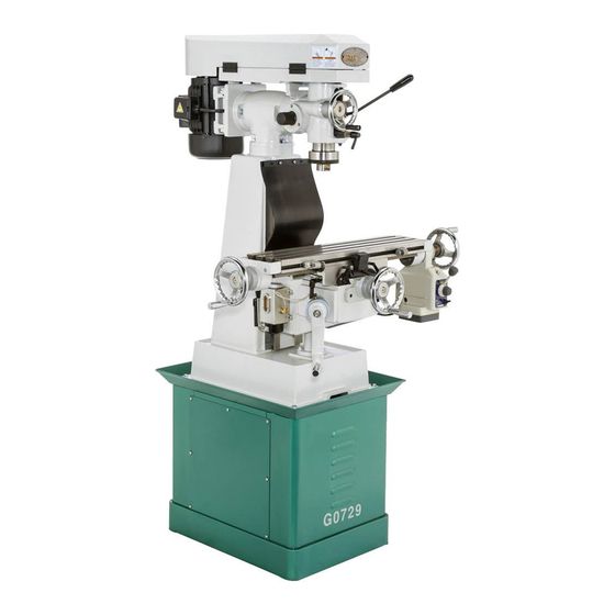
Models G0728, G0729, G0730
& G0731
VERTICAL MILLING MACHINES
OWNER'S MANuAL
(For models manufactured since 11/11)
Copyright © DECEMBEr, 2011 By grizzly inDustrial, inC., rEvisED FEBruary, 2013 (tr)
WARNING: NO pORTION Of THIS MANuAL MAy bE REpROduCEd IN ANy SHApE
OR fORM WITHOuT THE WRITTEN AppROVAL Of GRIzzLy INduSTRIAL, INC.
#Kn14570 printED in taiWan
Advertisement
Table of Contents

Related Manuals for Grizzly G0728


Summary of Contents for Grizzly G0728
- Page 1 OWNER'S MANuAL (For models manufactured since 11/11) Copyright © DECEMBEr, 2011 By grizzly inDustrial, inC., rEvisED FEBruary, 2013 (tr) WARNING: NO pORTION Of THIS MANuAL MAy bE REpROduCEd IN ANy SHApE OR fORM WITHOuT THE WRITTEN AppROVAL Of GRIzzLy INduSTRIAL, INC.
- Page 2 This manual provides critical safety instructions on the proper setup, operation, maintenance, and service of this machine/tool. Save this document, refer to it often, and use it to instruct other operators. Failure to read, understand and follow the instructions in this manual may result in fire or serious personal injury—including amputation, electrocution, or death.
-
Page 3: Table Of Contents
Table of Contents INTROduCTION ..........2 SECTION 4: OpERATIONS ......19 Manual accuracy ........... 2 operation safety .......... 19 Contact info............ 2 Basic Controls ..........19 Machine Description ........2 table Movement .......... 20 identification ........... 3 head tilting ..........22 Machine Data sheet ........ -
Page 4: Introduction
For your convenience, we post all available man- uals and manual updates for free on our website at www.grizzly.com. Any updates to your model of machine will be reflected in these documents as soon as they are complete. -
Page 5: Identification
Identification Coarse Downfeed v-Belt Cover handle v-Belt tension adjustment Bolt Fine Downfeed handwheel spindle Bearing oil Cup on/oFF spindle Direction switch longitudinal limit stop track X-axis Crank handwheel y-axis Feed limit stop track Cross Feed handwheel Knee Front view Downfeed selector Motor 1 ⁄... -
Page 6: Machine Data Sheet
Machine data Sheet MODEL G0728/G0729/G0730/G0731 VERTICAL MILLING MACHINES Model Number G0728 G0729 G0730 G0731 product dimensions Weight 660 lbs. 671 lbs. 924 lbs. 935 lbs. Width x depth x Height ⁄ " x 49 ⁄ " x 68" ⁄ " x 42 ⁄... - Page 7 Model Number Model Number G0728 G0728 G0729 G0729 G0730 G0730 G0731 G0731 Operation Info (cont'd) Swing 13" 14" Longitudinal Table Travel ⁄ " 18" Cross Table Travel 6" ⁄ " Knee Travel ⁄ " ⁄ " Head Swivel (Left-to-right) 45° left/right Turret/Column Swivel (Left and Right) 360°...
-
Page 8: Section 1: Safety
SECTION 1: SAfETy For Your Own Safety, Read Instruction Manual Before Operating This Machine The purpose of safety symbols is to attract your attention to possible hazardous conditions. This manual uses a series of symbols and signal words intended to convey the level of impor- tance of the safety messages. - Page 9 INTENdEd usAGE. Only use machine for its machine in good working condition. A machine intendedpurposeandnevermakemodifications that is improperly maintained could malfunction, not approved by Grizzly. Modifying machine or leadingtoseriouspersonalinjuryordeath. using it differently than intended may result in ChECK dAMAGEd PARTs. Regularly inspect...
-
Page 10: Additional Safety Instructions For Mills
Additional Safety Instructions for Mills uNdERSTANdING CONTROLS: the mill is a STOppING SpINdLE: to reduce the risk of complex machine that presents severe cutting or hand injuries or entanglement hazards, Do not entanglement hazards if used incorrectly. Make attempt to stop the spindle with your hand or a sure you understand the use and operation of all tool. -
Page 11: Section 2: Power Supply
SECTION 2: pOWER SuppLy Availability Circuit Information Before installing the machine, consider the avail- A power supply circuit includes all electrical ability and proximity of the required power supply equipment between the breaker box or fuse panel circuit. If an existing circuit does not meet the in the building and the machine. -
Page 12: Extension Cords
Grounding Requirements GROUNDED This machine MUST be grounded. In the event 6-15 RECEPTACLE of certain malfunctions or breakdowns, grounding Current Carrying Prongs reduces the risk of electric shock by providing a path of least resistance for electric current. 6-15 PLUG For 110V operation: This machine is equipped with a power cord that has an equipment-ground- ing wire and a grounding plug (see following fig-... - Page 13 Voltage Conversion Motor prewired for 110V to convert this mill for 220v power, you must re- wire the motor and install a nEMa 6-15 plug and receptacle. refer to page 40 for the full Wiring diagram. you MuST disconnect the mill from the power source before beginning any of the following 220V conver-...
-
Page 14: Section 3: Setup
SECTION 3: SETup Setup Safety Needed for Setup the following items are needed to complete the setup process, but are not included with your machine: This machine presents serious injury hazards description to untrained users. Read • assistants ........... 2 through this entire manu- •... -
Page 15: Inventory
Before cleaning, gather the following: • Disposable Rags • Cleaner/degreaser (WD•40 works well) Inventory Cleanup • Safety glasses & disposable gloves • Plastic paint scraper (optional) Basic steps for removing rust preventative: the following is a description of the main compo- The unpainted surfaces of your machine are nents shipped with your machine. -
Page 16: Site Considerations
Site Considerations Weight Load Physical Environment Refer to the Machine Data Sheet for the weight The physical environment where the machine is of your machine. Make sure that the surface upon operated is important for safe operation and lon- which the machine is placed will bear the weight gevity of machine components. -
Page 17: Moving & Placing Base Unit
Moving & placing use a ⁄ " wrench to unbolt the mill from the pallet. base unit With assistance to steady the machine, move it as close to the prepared location as pos- sible. lift it just enough to clear the pallet and any floor obstacles, then situate it in its final posi- The vertical mill is a tion. -
Page 18: Mounting
Mounting NOTICE Anchor studs are stronger and more per- manent alternatives to lag shield anchors; although not required, we recommend that you however, they will stick out of the floor, mount your new machine to the floor. Because which may cause a tripping hazard if you this is an optional step and floor materials may decide to move your machine. -
Page 19: Assembly
Assembly remove the retaining ring from the end of the vertical crank screw, install the crank handle, then re-install the retaining ring, as shown in figure 13. gather the needed tools and components listed in Needed for Setup on page 12. To assemble the mill: secure the three handles to the handwheels, as shown in figures 11 and 12. -
Page 20: Initial Lubrication
Initial Lubrication power Connection After you have completed all previous setup this mill has numerous moving metal-to-metal instructions and circuit requirements, the machine contacts that require proper lubrication to help is ready to be connected to the power supply. ensure efficient and long-lasting mill operation. however, some lubrication must be performed To avoid unexpected startups or property dam- manually. -
Page 21: Test Run
Test Run To test run the machine: Make sure you understand the safety instruc- tions at the beginning of the manual and that once the assembly is complete, test run your the machine is set up properly. machine to make sure it runs properly and is ready for regular operation. -
Page 22: Spindle Break-In
Spindle break-In Successfully complete the spindle break-in procedure to avoid rapid wear of spindle it is essential to closely follow the proper break-in components when placed into operation. procedures to ensure trouble-free performance of this mill. To perform the spindle break-in procedure: adjust the pulleys to set the spindle speed to 230 rpM (g0728/g0729), or 270 rpM do not attempt to perform the spindle break-... -
Page 23: Section 4: Operations
Regardless of the content in this section, Grizzly Industrial will not be held liable for accidents caused by lack of train- ing. -21-... -
Page 24: Table Movement
Table Movement Knee lock this mill table has three paths of movement that are controlled by the corresponding handwheels or the vertical crank handle (see figure 18). Logitudinal (X-Axis) saddle lock or Left & Right Cross Feed figure 20. saddle and knee locks. (Y-Axis) or In &... - Page 25 Longitudinal power feed System Tools Needed Wrench or socket 12mm ........1 the g0729 and g0731 vertical mills are equipped with a longitudinal power feed and limit switch for To operate the longitudinal power feed: controlled X-axis table movement. refer to figure 23 and the descriptions below to understand the loosen the table locks (see figure 24).
-
Page 26: Head Tilting
Head Tilting rotate the speed dial to the minimum speed (all the way to the left), and use the direction lever to select the direction of table travel. the head tilts 90° to the left or right (see Flip the on/oFF switch up to turn the power figure 25). -
Page 27: Turret Rotation
To rotate the turret left or right: tilt the head to the left or right and use the head tilt scale to determine the angle of tilt. DisConnECt thE Mill FroM poWEr! re-tighten the four hex nuts and lock washers to secure the head. -
Page 28: Tramming Spindle
Tramming Spindle Center the parallel block under the spindle and tighten the table, knee, and quill locks to eliminate unwanted movement. tramming the spindle ensures that the spindle With the test indicator attached to the indica- and table are perpendicular along the X-axis (see tor holder, mount the holder in the spindle. -
Page 29: Adjusting Spindle Speed
Adjusting Spindle Setting Spindle Speed Tools Needed Speed Wrench 24 mm ..........2 To set the spindle speed: to select the correct spindle speed (rpM) for a DisConnECt thE Mill FroM poWEr. milling operation, you will need to: 1) Determine the spindle speed needed for the workpiece, release motor pulley tension by loosening and 2) configure the belts to provide the closest... -
Page 30: Downfeed Controls
downfeed Controls A. Quill dog: Moves with the quill. use the pointer on the side with the downfeed scale to determine the depth of downfeed. refer to figures 34–35 and the following descrip- b. downfeed Scale: Displays in inches the tions to understand the functions of the downfeed amount of quill travel. -
Page 31: Loading/Unloading Tooling
Loading/unloading open the v-belt cover and rotate the adjust- ment hex nut to the top of the drawbar to Tooling extend the drawbar fully within the spindle (see figure 37). this mill is equipped with a ⁄ "-20 drawbar (see figure 36). -
Page 32: Section 5: Accessories
To minimize this risk, only install accessories recommended for this machine by Grizzly. NOTICE Refer to the newest copy of the Grizzly Catalog for other accessories available for this machine. figure 39. g1075 52-pC. Clamping Kit. - Page 33 ⁄ " end mills. drives with oil immersion and satin chrome dials. see the current grizzly catalog for full specifica- tions. Features: 4.330" overall height (horizontal), 6.750" height to center hole (vertical), #3 Morse taper, 0.465" t-slot width, and 117 lbs. approxi- mate shipping weight.
-
Page 34: Section 6: Maintenance
Way oil, g96 gun treatment, ® slipit , or Boeshield t-9 (see grizzly Catalog ® ® before daily Operation: for more details). • Check/tighten loose mounting bolts. - Page 35 One-Shot Oiler Quill Gearing Lubricant frequency Lubricant frequency iso 68 lubricant or Every iso 68 lubricant or Every Equivalent 8 hours pump Equivalent 8 hours Drops of operation of operation the oil lines running from the one-shot oiler feed lift the cap of the oil cup shown in figure 46 to lubrication to the ways of the column (knee), add the lubricant.
-
Page 36: V-Belt Tensioning
V-belt Tensioning Leadscrews Lubricant frequency nlgi #2 grease Every thin power is transferred from the motor to the spindle 40 hours Coat with a v-belt. With normal use, this belt will gradu- of operation ally stretch over time. When it does, perform the following procedures to re-tension it. -
Page 37: Section 7: Service
SECTION 7: SERVICE review the troubleshooting and procedures in this section to fix or adjust your machine if a problem devel- ops. if you need replacement parts or you are unsure of your repair skills, then feel free to call our technical support at (570) 546-9663. - Page 38 Operation symptom possible Cause possible solution tool slips in collet. 1. Collet is not fully drawn into spindle taper. 1. snug up drawbar. 2. Wrong size collet. 2. use correct collet for shank diameter. 3. Debris on collet or spindle mating surface. 3.
-
Page 39: Adjusting Gibs
Adjusting Gibs gibs control the accuracy of table movement along the ways. tight gibs make the movement more accurate, but harder to move. loose gibs make the movement sloppy, but easier to move. the goal of gib adjustment is to remove unnec- essary sloppiness without causing the ways to table gib adjustment bind. -
Page 40: Adjusting Backlash
Screws Adjusting backlash Cross leadscrew nut leadscrew backlash is the amount of motion the leadscrew rotates before the device begins to move. leadscrews always have a certain amount of backlash which increases with wear. generally, 0.005"–0.010" of backlash is an acceptable range. -
Page 41: Section 8: Wiring
Technical source. Support at (570) 546-9663. The photos and diagrams included in this section are best viewed in color. You can view these pages in color at www.grizzly.com. -39- Model G0728–31 (Mfg. Since 11/11) -
Page 42: Wiring
electrical panel wiring Wiring Motor Motor Rewired for 220V Prewired for 110V Ground Start Capacitor 500MFD 125VAC Ground Motor terminal figure 57. Motor terminal location. Switch Box Front Ground View switch Box 12 9 figure 58. switch box location. Plug Rewired for 220V Ground 6-15 Plug (As Recommended) -
Page 43: Section 9: Parts
SECTION 9: pARTS G0728 & G0729 Head breakdown -41- Model G0728–31 (Mfg. Since 11/11) - Page 44 G0728 & G0729 Head parts List REF PART # DESCRIPTION REF PART # DESCRIPTION P0728101 SPINDLE NUT P0728131 SPINDLE NUT P0728102 SPANNER LOCK WASHER P0728132 LOCK KNOB SHAFT P0728103 SPINDLE PULLEY P0728133 LOCK BLOCK SLEEVE P0728104 SPLINE SLEEVE P0728134 COMPRESSION SPRING P0728105 BEARING COVER P0728135...
- Page 45 G0728 & G0729 drive System breakdown 207-3 207-1 207-2 207-10 207-4 207-5 207-7 207-6 207-8 207-9 PART # DESCRIPTION REF PART # DESCRIPTION P0728201 WOODRUFF KEY 5 X 40 PB56 HEX BOLT 1/2-13 X 1-3/4 PVA32 V-BELT A32 P0728215 MOUNTING PLATE PSS03M SET SCREW M6-1 X 8 P0728216...
- Page 46 G0728 & G0729 Table & Saddle breakdown G0729 Only 344-5 344-4 344-9 344-10 344-2 344-8 344-7 344-6 344-1 344-3 G0728 Only REF PART # DESCRIPTION PART # DESCRIPTION P0728301 HANDLE 3/8-16 X 1/2 P0728328 LOCK LEVER PN04 HEX NUT 5/8-11 P0728329 TABLE LOCKING LEVER PSS03M...
- Page 47 G0728 & G0729 Knee & base breakdown 464 465 -45- Model G0728–31 (Mfg. Since 11/11)
- Page 48 G0728 & G0729 Knee & base parts List REF PART # DESCRIPTION REF PART # DESCRIPTION P0728403 COLUMN P0728437 LEADSCREW PCAP68M CAP SCREW M6-1 X 8 P0728438 PEDESTAL P0728406 KNEE GIB P0728441 MACHINE BASE P0728407 GIB ADJUSTMENT SCREW P0728444 LIMIT TRACK P0728409 KNEE PB01M...
- Page 49 MuST maintain the original location and readability of the labels on the machine. If any label is removed or becomes unreadable, REpLACE that label before using the machine again. Contact Grizzly at (800) 523-4777 or www.grizzly.com to order new labels. -47-...
- Page 50 G0730 & G0731 Head breakdown 109 110 -48- Models G0728–31 (Mfg. Since 11/11)
- Page 51 G0730 & G0731 Head parts List REF PART # DESCRIPTION REF PART # DESCRIPTION P0728101 SPINDLE NUT P0731606 SPINDLE COLLAR P0730102 SPANNER LOCK WASHER P0728132 LOCK KNOB SHAFT P0730103 SPINDLE PULLEY P0728133 LOCK BLOCK SLEEVE P0728104 SPLINE SLEEVE P0728134 COMPRESSION SPRING P0730105 BEARING COVER P0728135...
- Page 52 G0730 & G0731 drive System breakdown 207-3 207-1 207-2 207-4 207-5 207-6 207-7 207-9 207-10 207-8 207-11 207-12 PART # DESCRIPTION REF PART # DESCRIPTION P0730201 WOODRUFF KEY 5 X 40 PB56 HEX BOLT 1/2-13 X 1-3/4 PVB35 V-BELT B35 P0728215 MOUNTING PLATE PSS03M...
- Page 53 G0730 & G0731 Table & Saddle breakdown G0731 Only 344-5 344-3 344-9 344-10 344-8 344-1 344-7 344-6 344-4 344-2 307 343 G0730 Only REF PART # DESCRIPTION PART # DESCRIPTION P0730301 HANDLE 3/8-16 X 1/2 P0730328 SADDLE LOCK SCREW PN04 HEX NUT 5/8-11 P0730329 TABLE LOCK SCREW...
- Page 54 G0730 & G0731 Knee & base breakdown 457 456 442 441 461 462 -52- Models G0728–31 (Mfg. Since 11/11)
- Page 55 G0730 & G0731 Knee & base parts List REF PART # DESCRIPTION REF PART # DESCRIPTION PS68M PHLP HD SCR M6-1 X 10 P0731606 CROSS FEED LEADSCREW P0730403 COLUMN P6204ZZ BALL BEARING 6204ZZ PCAP68M CAP SCREW M6-1 X 8 P0730437 VERTICAL LEADSCREW P0728406 KNEE GIB...
- Page 56 MuST maintain the original location and readability of the labels on the machine. If any label is removed or becomes unreadable, REpLACE that label before using the machine again. Contact Grizzly at (800) 523-4777 or www.grizzly.com to order new labels. -54-...
-
Page 57: Warranty Card
Would you recommend Grizzly Industrial to a friend? _____ Yes _____No Would you allow us to use your name as a reference for Grizzly customers in your area? Note: We never use names more than 3 times. _____ Yes _____No 10. - Page 58 FOLD ALONG DOTTED LINE Place Stamp Here GRIZZLY INDUSTRIAL, INC. P.O. BOX 2069 BELLINGHAM, WA 98227-2069 FOLD ALONG DOTTED LINE Send a Grizzly Catalog to a friend: Name_______________________________ Street_______________________________ City______________State______Zip______ TAPE ALONG EDGES--PLEASE DO NOT STAPLE...
-
Page 59: Warranty And Returns
WARRANTY AND RETURNS Grizzly Industrial, Inc. warrants every product it sells for a period of 1 year to the original purchaser from the date of purchase. This warranty does not apply to defects due directly or indirectly to misuse, abuse, negligence, accidents, repairs or alterations or lack of maintenance. - Page 60 Buy Direct and Save with Grizzly – Trusted, Proven and a Great Value! ® ~Since 1983~ Visit Our Website Today For Current Specials! ORDER 24 HOURS A DAY! 1-800-523-4777...