Table of Contents
Advertisement
Quick Links
model g0705
mill/drill w/stand
oWner's manual
Copyright © MarCh, 2010 By grizzly industrial, inC. revised deCeMBer, 2010 (JB)
Warning: no portion of this manual may be reproduced in any shape
or form Without the Written approval of grizzly industrial, inc.
(For Models ManuFaCtured sinCe 09/09) #JB12469 printed in China
Advertisement
Table of Contents

Related Manuals for Grizzly G0705


Summary of Contents for Grizzly G0705
- Page 1 Copyright © MarCh, 2010 By grizzly industrial, inC. revised deCeMBer, 2010 (JB) Warning: no portion of this manual may be reproduced in any shape or form Without the Written approval of grizzly industrial, inc.
- Page 2 This manual provides critical safety instructions on the proper setup, operation, maintenance, and service of this machine/tool. Save this document, refer to it often, and use it to instruct other operators. Failure to read, understand and follow the instructions in this manual may result in fire or serious personal injury—including amputation, electrocution, or death.
-
Page 3: Table Of Contents
Backlash ... 44 section 8: Wiring ... 45 Wiring safety instructions ... 45 g0705 Wiring diagram ... 46 g0705 Wiring diagram (Continued) ... 47 section 9: parts ... 48 headstock parts Breakdown ... 48 headstock parts list ... 49 headstock parts list (continued) ... -
Page 4: Introduction
Your Machine For your convenience, we post all available man- uals and manual updates for free on our website at www.grizzly.com. Any updates to your model of machine will be reflected in these documents as soon as they are complete. -
Page 5: Identification
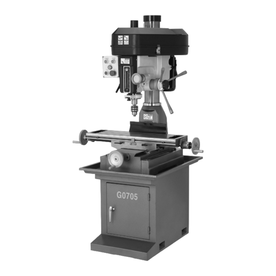
Fine downfeed handwheel h. Column table longitudinal handwheel K. table stop Cross travel lock Model g0705 (Mfg. since 09/09) identification figure 1. Model g0705 identification. m. longitudinal travel lock n. Cabinet stand o. Mounting Bolt hole p. Cabinet door Q. -
Page 6: Machine Data Sheet
Customer Service #: (570) 546-9663 · To Order Call: (800) 523-4777 · Fax #: (800) 438-5901 MODEL G0705 DRILL/MILL WITH STAND 29 INCH X 8 INCH Product Dimensions: Weight... 617 lbs. Length/Width/Height...41-5/8 x 40-1/2 x 43-1/4 in. Foot Print (Length/Width)... 28-3/8 x 17-3/4 in. - Page 7 The information contained herein is deemed accurate as of 12/20/2010 and represents our most recent product specifications. Model G0705 Due to our ongoing improvement efforts, this information may not accurately describe items previously purchased. Model g0705 (Mfg. since 09/09) PAGE 2 OF 3...
- Page 8 The information contained herein is deemed accurate as of 12/20/2010 and represents our most recent product specifications. Model G0705 Due to our ongoing improvement efforts, this information may not accurately describe items previously purchased. PAGE 3 OF 3 Model g0705 (Mfg. since 09/09)
-
Page 9: Section 1: Safety
NIOSH-approved respirator to reduce your risk. Model g0705 (Mfg. since 09/09) WEARING PROPER APPAREL. Do not wear clothing, apparel, or jewelry that can become entangled in moving parts. Always tie back or cover long hair. - Page 10 Always repair or replace damaged or mis- adjusted parts before operating machine. EXPERIENCING DIFFICULTIES. If at any time you are experiencing difficulties performing the intended operation, stop using the machine! Contact our Technical Support Department at (570) 546-9663. Model g0705 (Mfg. since 09/09)
-
Page 11: Additional Safety For Mill/Drills
injury. -
Page 12: Section 2: Circuit Requirements
The intended 110V circuit must have a verified ground and meet the follow- ing requirements: nominal voltage ... 110v/120v cycle ...60 hz phase ... single-phase circuit rating ... 30 amps plug/receptacle ... nema 5-20 Model g0705 (Mfg. since 09/09) -
Page 13: V Conversion
Neutral 5-20 PLUG Grounding Prong figure 3. typical 5-20 plug and receptacle. Model g0705 (Mfg. since 09/09) Serious injury could occur if you connect the machine to power before completing the setup process. DO NOT connect to power until instructed later in this manual. - Page 14 110v conversion the Model g0705 can be converted for 110v operation. this conversion job consists of dis- To Motor connecting the machine from the power source, replacing the contactors and power indicator lamp, and rewiring the motor. the necessary components for this procedure can be purchased in the Model g0705 110v Conversion Kit (part no.
- Page 15 7. Contactor release tab location. install the two 110v contactors from the Model g0705 110v Conversion Kit in place of the contactors you removed in step 4. replace the wires you removed in step 3 to the corresponding terminals on the 110v con- tactors.
- Page 16 3 onto the power cord, as illustrated in figure 10. refer to section 8: Wiring starting on page 45 for detailed wiring diagrams. Cord Rewired for 110V Neutral (As Recommended) Ground figure 10. Cord rewired for 110V. Model g0705 (Mfg. since 09/09) L5-30 Plug...
-
Page 17: Section 3: Setup
(rated for at least 750 lbs.) ... 1 • another person ... 1 unpacking the Model g0705 was carefully packed when it left our warehouse. if you discover the machine is damaged after you have signed for delivery, please immediately call Customer Service at (570) 546-9663 for advice. -
Page 18: Inventory
Bolts M12-1.75 x 40 ... 4 • hex nuts M12-1.75 ... 4 • Cap screws M6-1 x 16 ... 3 • Flat Washers 6mm ... 3 • drawbar ... 1 -16- figure 11. Main inventory. figure 12. inventory. Model g0705 (Mfg. since 09/09) -
Page 19: Cleanup
WD•40 can be used to remove rust pre- ventative. Before using these products, though, test them on an inconspicuous area of your paint to make sure they will not damage it. Model g0705 (Mfg. since 09/09) Gasoline and petroleum products have low flash points and can explode or cause fire if used to clean machinery. -
Page 20: Site Considerations
Lighting around the machine must be adequate enough that operations can be performed safely. Shadows, glare, or strobe effects that may distract or impede the operator must be eliminated. Wall 30" 42" 61.5" 39" 44" Model g0705 (Mfg. since 09/09) -
Page 21: Mounting Options
Model g0705 (Mfg. since 09/09) using the included leveling bolt thread one M12-1.75 x 40 hex bolt with one M12-1.75 hex nut into the bolt mounting hole on each corner of the base, as shown in figure 15. -
Page 22: Mounting To Shop Floor
NOTICE We strongly recommend securing your machine to the floor if it is hardwired to the power source. consult with your electrician to ensure compliance with local codes. Model g0705 (Mfg. since 09/09) - Page 23 19. example of a direct mount setup. Model g0705 (Mfg. since 09/09) assembly assembly of the Model g0705 consists of attach- ing the three handwheel handles to the machine. to assemble your machine: use one M6-1 x 16 cap screw and 6mm flat washer to install each handwheel in the loca- tions shown in figure 20.
-
Page 24: Moving & Placing Machine
—if you mounted your machine to the cabinet and mounted the cabinet to the floor, use a precision level and metal shims as needed to make sure the machine table is level from side-to-side and from front-to-back. Model g0705 (Mfg. since 09/09) -
Page 25: Test Run
Make sure all tools and objects used during setup are cleared away from the machine. Connect the machine to the power source. Model g0705 (Mfg. since 09/09) push the eMergenCy stop button in, then twist it clockwise (see figure 22) so it pops out. -
Page 26: Break-In
29. turn the spindle ON and let it run for a mini- mum of 10 minutes. repeat this step for each rpM setting. refer to speed changes on page 29. Model g0705 (Mfg. since 09/09) -
Page 27: Section 4: Operations
Model g0705 (Mfg. since 09/09) operation overview... -
Page 28: Basic Controls
Knob: engages/disengages the micro- adjustment handwheel. Quill downfeed levers: provide coarse control over vertical spindle travel. Fine downfeed handwheel Quill downfeed levers figure 24. spindle controls. Model g0705 (Mfg. since 09/09) depth stop locking Knob... - Page 29 Can be loosened for headstock repositioning Motor locking lever figure 26. Headstock controls. Model g0705 (Mfg. since 09/09) head crank: Changes the elevation of the entire headstock. head Crank table locks reverse button: Moves the spindle in a counter- clockwise direction.
-
Page 30: Calculating Spindle Speed For Milling
Model g0705 (Mfg. since 09/09) -
Page 31: Speed Changes
Model g0705 is capable of twelve different speed settings. different types of cuts and materi- als require varying speeds. refer to the chart in figure 29 for appropriate cutting speeds. tools needed hex Wrench 6mm ... 1... -
Page 32: Calculating Spindle Speed For Drilling
1000 figure 33. drill bit speed chart. Brass Aluminum Mild Steel 2500 3000 2500 1250 2500 1250 1500 1000 Brass Aluminum Mild Steel Brass Aluminum Mild Steel Brass Aluminum Mild Steel Brass Aluminum Mild Steel Model g0705 (Mfg. since 09/09) -
Page 33: Spindle Height
Model g0705 has coarse downfeed levers and a micro-adjustment handwheel. to operate the downfeed levers, simply pull forward and down on the lever nearest you. the spindle will go down until you stop pulling or until it hits the depth stop. -
Page 34: Loading Tooling
Model g0705 features an r-8 spindle that accepts r-8 collets and arbors. to install tooling: disConneCt MaChine FroM poWer! release the latches on the head cover and open it. Make sure the tapered mating surfaces of the cutting tool and the spindle are clean and free of grease or other contaminants. -
Page 35: Drill Chuck Arbor
Model g0705 (Mfg. since 09/09) collet adapters the Model g0705 includes two adapters that will allow the use of Mt#3 and Mt#2 tooling. a drift key is also included to aid in the separation of the adapters and any installed tooling. -
Page 36: Headstock Position
Model g0705 can be adjusted for various applications. For increased quill rigidity and reduced vibrations, which will produce the best results, keep the quill fully retracted and set the headstock as low as possible. -
Page 37: Table Travel
X-axis table lock levers X-axis scale y-axis table lock lever figure 43. table locks and scales. Model g0705 (Mfg. since 09/09) cross feed the cross handwheel shown in figure 42 move the table along the cross axis (y-axis). one complete revolution of the handwheel moves the cross slide 0.100". -
Page 38: Section 5: Accessories
10 second vernier scales, gear drives with oil immersion and satin chrome dials. see the current grizzly catalog for full specifica- tions. Features: 4.330" overall height (horizontal), 6.750" height to center hole (vertical), #3 Morse taper, 0.465"... - Page 39 ", ", ", ", ". figure 51. g9765 9 pC. Ball end Mill set. Model g0705 (Mfg. since 09/09) g5641—1-2-3 blocks g9815—parallel set h5556—edge finder set g5641 g9815 figure 52. g5641 1-2-3 Blocks, g9815 parallel set, and h5556 edge Finder set.
-
Page 40: Section 6: Maintenance
Keep unpainted cast iron surfaces rust-free with regular applications of products like g96 treatment, slipit , or Boeshield ® grizzly catalog or website). Model g0705 (Mfg. since 09/09) ® t-9 (see the ®... -
Page 41: Lubrication
Ways. periodically lubricate the ways with Mobil vactra 2 or way oil. figure 54. Ball oiler locations. Model g0705 (Mfg. since 09/09) table leadscrews every six months, or more frequently under heavy use, clean and lubricate the leadscrews. - Page 42 29 to loosen the belts. remove them from the pulleys, then install new v-belts. Deflection ⁄ " figure 57. Belt tension. Model g0705 (Mfg. since 09/09) Pulley Pulley...
-
Page 43: Section 7: Service
6. Quill is overextended. 7. Machine is incorrectly mounted or sits unevenly. 8. Motor bearings are at fault. Model g0705 (Mfg. since 09/09) troubleshooting possible solution 1. ensure circuit size is correct and a short does not exist. reset breaker or replace fuse. - Page 44 2. sharpen cutting tool or select one that better suits the operation. 3. Check for proper direction of cutting rotation for cutting tool. 4. secure properly to the table. 5. Fully retract spindle and lower headstock. this increases rigidity. Model g0705 (Mfg. since 09/09)
-
Page 45: Gibs
Model g0705 (Mfg. since 09/09) the tail end of the spring is located on the perimeter of the spring housing. this... -
Page 46: Leadscrew Backlash
X-axis leadscrew. leadscrew adjuster Model g0705 (Mfg. since 09/09) -
Page 47: Section 8: Wiring
You can view these pages in color at www.grizzly.com. Model g0705 (Mfg. since 09/09) WIRE/COMPONENT DAMAGE. Damaged wires or components increase the risk of serious per- sonal injury, fire, or machine damage. If you notice... -
Page 48: G0705 Wiring Diagram
110V/220V) Cord Rewired for 110V Neutral Ground -46- Capacitor 20 MFD 450 VAC L5-30 Plug (As Recommended) To Electrical Box Start Capacitor 150 MFD 250 VAC Ground To Electrical Box Ground 6-20 Plug Model g0705 (Mfg. since 09/09) -
Page 49: G0705 Wiring Diagram (Continued)
To Motor Electrical Box To Plug Motor electrical Box figure 62. Electrical component locations. Model g0705 (Mfg. since 09/09) Contactor Information (Contactor is wired the same for 110V/220V) FUSE Control Panel (Viewed From Behind) Indicator Light Type XDJ2(J) 220V AC... -
Page 50: Section 9: Parts
9: parts headstock parts breakdown -48- Model g0705 (Mfg. since 09/09) -
Page 51: Headstock Parts List
P0705016 DEPTH STOP ADJUSTER PCAP159M CAP SCREW 1/4-20 x 2 PN05 HEX NUT 1/4-20 P0705019 DEPTH STOP BLOCK Model g0705 (Mfg. since 09/09) REF PART # DESCRIPTION P0705020 PINION SHAFT PFH08 FLAT HD SCR 10-24 X 1/2 PK25M KEY 7 X 7 X 20... -
Page 52: Headstock Parts List (Continued)
HEX BOLT 7/16-14 X 3/4 PK109M KEY 7 X 7 X 35 P0705099 GUARD BRACKET PCAP03M CAP SCREW M5-.8 X 8 PCAP26M CAP SCREW M6-1 X 12 P0705102 PROTECTIVE PLATE P0705113 CHUCK B16 1–13MM 113-1 P0705113-1 CHUCK KEY Model g0705 (Mfg. since 09/09) -
Page 53: Base Parts Breakdown
-51- Model g0705 (Mfg. since 09/09) -
Page 54: Base Parts List
CROSS LEADSCREW ASSEMBLY COLUMN BASE ELEVATION RACK COLUMN CAP COLUMN RING HEX BOLT 5/8-11 X 2-1/2 LOCK WASHER 5/8 CAP SCREW 5/16-18 X 3/4 LOCK WASHER 5/16 DRAIN PLUG HEX BOLT M10-1.5 X 140 CABINET ASSEMBLY Model g0705 (Mfg. since 09/09) -
Page 55: Electrical Components Breakdown And List
P0705302 TERMINAL BLOCK ASSEMBLY P0705303 CONTACTOR SIEMENS 3TB41 220V P0705304 FORWARD BUTTON P0705305 POWER INDICATOR LAMP 220V P0705306 STOP BUTTON Model g0705 (Mfg. since 09/09) 14NO 22NC 32NC 44NO 14NO 22NC 32NC 44NO Electrical Box Control Panel (Viewed From Behind) -
Page 56: Labels Breakdown And List
(800) 523-4777 or www.grizzly.com to order new labels. -54-... -
Page 57: Warranty Card
Do you think your machine represents a good value? Would you recommend Grizzly Industrial to a friend? Would you allow us to use your name as a reference for Grizzly customers in your area? Note: We never use names more than 3 times. - Page 58 FOLD ALONG DOTTED LINE FOLD ALONG DOTTED LINE Send a Grizzly Catalog to a friend: Name_______________________________ Street_______________________________ City______________State______Zip______ GRIZZLY INDUSTRIAL, INC. P.O. BOX 2069 BELLINGHAM, WA 98227-2069 TAPE ALONG EDGES--PLEASE DO NOT STAPLE Place Stamp Here...
-
Page 59: Warranty And Returns
WARRANTY AND RETURNS Grizzly Industrial, Inc. warrants every product it sells for a period of 1 year to the original purchaser from the date of purchase. This warranty does not apply to defects due directly or indirectly to misuse, abuse, negligence, accidents, repairs or alterations or lack of maintenance. - Page 60 Buy Direct and Save with Grizzly – Trusted, Proven and a Great Value! ® ~Since 1983~ Visit Our Website Today For Current Specials! ORDER 24 HOURS A DAY! 1-800-523-4777...