Advertisement
Available languages
Available languages
Quick Links
Download this manual
See also:
User Manual
Advertisement

Related Manuals for Fisher & Paykel OR24SDPWGX


Summary of Contents for Fisher & Paykel OR24SDPWGX
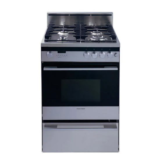
- Page 1 OR24SDPWGX model...
- Page 2 WARNING ,, ALL RANGES CAN TiP ,, iNJURY TO PERSON COULD RESULT ,, iNSTALL ANTI=TIP DEVICE PACKED WiTH RANGE ,, SEE iNSTALLATiON iNSTRUCTiONS WARNING" IF THE INFORMATION IN THIS MANUAL IS NOT FOLLOWED EXACTLY, A FIRE OR EXPLOSION RESULT CAUSING PROPERTY DAMAGE, PERSONAL...
- Page 3 DATA PLATE CONVERSION LABEL IMPORTANT - PLEASE READ AND FOLLOW ¢" Before beginning, please read these instructions completely carefully. ¢" Do not remove permanently affixed labels, warnings, or plates from the product. This may void the warranty. ¢" Please observe all local and national codes and ordinances.
-
Page 4: For Installation
WARNING! THIS APPLIANCE HAS TO BE INSTALLED BY A QUALIFIED INSTALLER. Improper installation, adjustment, alteration, services, or maintenance can cause injury or property damage. Consult a qualified installer, service agent, or the gas supplier. IMPORTANT: The use of suitable protective clothing/gloves is recommended when handling, installing of this appliance. -
Page 5: General Information
GENERAL INFORMATION WARNING!! 1. Installation must conform with local codes or, in the absence of local codes, with the National Fuel Gas Code, ANSI Z223.1-Latest Edition, CAN/CGA-B149.1 or CAN/CGA- ELECTRICAL GROUNDING INSTRUCTIONS B149.2. The range must be electrically grounded in accordance with local codes... - Page 6 installation PROXIMITY TO SIDE CABINETS • This range may be installed directly adjacent to existing 36" (914 mm) high base cabinets• Range dimensions: • width: 23" 7/8 (606.5 mm) • depth: 24" 11/64 (614.1 mm) • height (without backguard): MIN 35" 17/32 (902.5 mm) - MAX 36" 7/32 (920 mm) •...
- Page 7 PROXIMITY TO SIDE CABINETS 13"maX. ( 330ram) ram) Fig. 1.3 ASSEMBLING THE BACKGUARD It is mandatory to install the backguard Assemble the backguard as shown in figure 1.5: • Screw the 2 screws "A" interposing the spacers. • Screw the central screw "B". Fig.
- Page 8 LEVELLING THE RANGE The range is equipped with 4 LEVELLING FEET (supplied in a separate kit) and may be levelled by screwing or unscrewing the feet (fig. 1.8). It is important to observe the directions of figures 1.6, 1.7a, 1.7b. °...
- Page 9 connection All gas connections must be made according to national and local codes. This gas supply (service) line must be the same size or greater than the inlet line of the WARNING appliance. Sealant on all pipe joints must be resistant to the action of LP/Propane gas.
-
Page 10: Pressure Regulator
PRESSURE REGULATOR INSTALLATION STEP 1 Mount the 1/2" NPT (conical) male connector to the pressure regulator and tighten by using a wrench. LOCK Do not over tighten the connector. Over tightening may crack regulator. Fig. 2.2 STEP 2 Assemble the 1/2" NPT connector + pressure regulator group to the extension pipe interposing the gasket supplied. -
Page 11: Specification
GAS CONNECTION SPECIFICATION manifold I Manifold male pipe fitting I/2" G cylindrical (ISO 228-I) male 1/2" G cylindrical ISO 228-I) female EXtension ipe femak pipe fitting E×tensi pipe Extension I/2" G cylindrical pipe male (ISO 228-I) male pipe fitting I/2" G cylindrical (ISO 228-I) female Con"eCto, 1... - Page 12 b) Any conversion required must be performed by your dealer or a qualified licensed plumber or gas service company. Please provide the service person with this TEST POINT ADAPTER manual before work is started on the range. (Gas conversions are the responsibility The Test Point adapter is available of the dealer or end user.) from the After-Sales...
-
Page 13: Setting The Pressure
CONVERSION TO LP/PROPANE Every range is provided with a set of injectors for the various types of gas. Select the injectors to be replaced according to the "INJECTORS TABLE". The nozzle diameters, expressed in hundredths of a millimetre, are marked on the body of each injector. - Page 14 _f _='_,% To set the pressure regulator (fig. 2.9): _--_ _e_u_ re___ 1. Unscrew the regulator cover; 2. Unscrew the A component, reverse and screw it according to the LP/PROPANE regulation. REGULATOR COVER Fig. 2.9 NATURAL GAS LP/PROPANE REGULATION REGULATION Fitting the warming drawer...
- Page 15 INJECTORS TABLE NOMINAL REDUCED LP/PROPANE NATURAL GAS POWER POWER 11" W.C.R 4" W.C.R BTU/hr {3 injector By-pass O injector By-pass BURNERS BTU/hr [1/100 ram] [1/100mm] [1/100 mm] [1/100mm] Auxiliary (AUX) 3500 1000 adjustable Semirapid (SR) 6000 1500 adjustable Triple ring (TC) 12000 5000 adjustable...
- Page 16 electrical connection If codes permit and a separate ground wire is used, it is recommended that a qualified electrician installer determine that the ground path and wire gauge are in accordance with local codes. Be sure that the electrical connection and wire size are adequate and in conformance with: - ANSl/NFPA 70 latest edition and local codes and ordinances - CSA Standard C22.1, Canadian Electrical Code, Part 1 - latest edition, and all local...
- Page 17 I-_ °:...
- Page 18 AVERTISSENIENT ,, TOUS LES TYPES DE CUISINli_RE PEUVENT BASCULER ,, CELA PEUT PROVOQUER DES BLESSURES ,, INSTALLEZ LE DISPOSITIF ANTIBASCULEMENT FOURNI AVEC LA CUISINli_RE e CONSULTEZ LES iNSTRUCTiONS D'INSTALLATION AVIERTISSlEMIENT : SI L'INFORMATION CONTENUE DANS MANUEL N'EST PAS SUIVIE A LA LETTRE, UN INCENDIE UNE EXPLOSION PEUVENT...
- Page 19 PLAQUE SIGNALFtTIQUE FtTIQUETTE DE CONVERSION IMPORTANT - VEUILLEZ LIRE ET SUIVRE v" Avant de commencer, veuillez lire attentivement toutes les instructions. N'enlevez pas les etiquettes, plaques ou avertissements permanents I'appareil. Cela pourrait annuler la garantie. ,/ Veuillez respecter tousles codes et les r_glements Iocaux et nationaux.
- Page 20 AVERTISSEMENT! CET APPAREIL DOlT ETRE INSTALLI_ PAR UN INSTALLATEUR QUALIFII_. Une mauvaise installation, modification, r_paration ou un mauvais reglage ou entretien peuvent causer des blessures ou des dommages materiels. Consultez un installateur qualifi_, un agent autoris_ ou le fournisseur de gaz. IMPORTANT : L'utilisation de v_tements et de gants de protection est recommand_e...
-
Page 21: Pieces De Rechange
RENSEIGNEMENTS GC:NC:RAUX 1. L'installation dolt 6tre conforme aux codes Iocaux ou, en AVERTISSEMENT!! I'absence de ceux-ci, & la derniere edition du National Fuel Gas Code, ANSI Z223.1, au CAN/CGA-B149.1 ou au CAN/ INSTRUCTIONS DE MISE A LA TERRE CGA-B149.2. La cuisini_re doit _tre mise a la terre conformement 2. - Page 22 installation PROXIMITI_ DES ARMOIRES 1. Cette cuisiniere peut 6tre installee directement adjacente & des armoires de base existantes de 36 po (914 mm) de hauteur. Dimensions de la cuisiniere • largeur : 23-7/8 po (606,5 mm) • profondeur : 24-11/64 po (614,1 mm) •...
- Page 23 PROXIMITI_ DES ARMOIRES 13pol 13po 3Po(76mm Fig. 1.4 MONTAGE DU DOSSERET L'installation du dosseret est obligatoire, Montez le dosseret tel qu'indique a la figure 1.5 : • Vissez les 2 vis ,_A _ en interposant les butoirs. • Vissez la vis centrale _ B _. Fig.
- Page 24 S _ _,_'_"_!_ MISE A NIVEAU DE LA CUISINIERE La cuisiniere est munie de 4 PIEDS DE MISE A NIVEAU (fournis dans une trousse sepa- ree) et peut _tre mise & niveau en vissant ou en devissant ces pieds (fig. 1.8). II est important de respecter les instructions des figures 1.6, 1.7a, 1.7b.
- Page 25 raccordement Tousles raccordements au gaz doivent _tre effectues conformement aux codes natio- naux et Iocaux. Ce tuyau d'alimentation en gaz dolt _tre du m_me format ou plus grand que la conduite de I'appareil. Le produit d'etancheite sur tousles joints de tuyau dolt AVERTISSEMENT 6tre resistant &...
- Page 26 INSTALLATION DU RI_GULATEUR DE PRESSION I_TAPE 1 Montez le connecteur m&le (conique) NPT de 1/2 po sur le regulateur FERMER de pression et serrez avec une clef. Ne serrez pas le connecteur outre mesure. Trop serrer pourrait entra_ner une fissure dans le regulateur. Fig.
- Page 27 SPleCIFICATION DU RACCORDEMENT AU GAZ Collecteur ia cuisini_re dU toyao d uooHeoteur M&le G cylindrique (ISO 228-1) de 1/2 po Femelle G cylindrique Vers la cuisiniere Raccord femelle_ _ (ISO 228-1) de 1/2 po du tuyau de _ Pr01qngati°n "_ ,L,,, prolongation_ du tuyau de...
- Page 28 Toute conversion requise dolt _tre effectuee soit par votre detaillant, soit par un tech- nicien agree qualifie ou par la societe gaziere. Veuillez remettre le present manuel au ADAPTATEUR DU POINT technicien avant de commencer I'entretien de la cuisiniere. (Les conversions de gaz D'I_PREUVE sent la responsabilite...
- Page 29 CONVERSION AU GAZ PROPANE/GPL Chaque cuisiniere est fournie avec un ensemble d'injecteurs pour les divers types de gaz. Choisissez les injecteurs a _tre remplaces selon le ,, TABLEAU DES INJECTEURS _. Le diametre de la busette, exprime en centiemes de millimetre, est indique sur le corps de chaque injecteur.
- Page 30 _f _='_,% Pour r_gler le r_gulateur de pression (fig. 2.9) : 1. Devissez le couvercle du regulateur. 2. Devissez le composant A, inversez-le et vissez-le selon le reglage PROPANE/GPL. COUVERCLE DU REGULATEUR Fig. 2.9 REGLAGE REGLAGE GAZ NATUREL PROPANE/GPL Installation du tiroir de maintien au chaud (fig.
- Page 31 TABLEAU DES INJECTEURS PUISSANCE PUISSANCE PROPANE/GPL GAZ NATUREL NOMINALE REDUITE Pressionde 11 poCE Pressionde 4 po CE BRULEURS BTU/h BTU/h Injecteur {3 D6rivation Injecteur O D_rivation [1/100 ram] [1/100mm] [1/100 mm] [1/100mm] Auxiliaire (AUX) 3 500 1 000 reglable Semi-rapide (SR) 6 000 1 500 reglable...
- Page 32 raccordement lectrique Si les codes le permettent et qu'un fil de mise a la terre distinct est utilis_, il est recommande qu'un _lectricien qualifie d_termine que le trajet de mise a la terre et le calibre du fil sent conformes aux codes Iocaux. Assurez-vous que le raccordement electrique et que la taille du fil sent adequats et...
- Page 33 .__ = ¢) ,l,IJ ¢)
- Page 34 Copyright _ Fisher & Paykel 2007. All rights reserved. The oroauc_ soecifications - this DOOKle_appb _c _ne s_ecific droauc_s a]a r'nodels aesc'ibed at _ne aa_e Df issue, unaer our policy of continu }us Dr }auc_ _-orover'nenL _nese soecificatior s r'nsx cnange a_ any time.