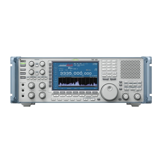
Icom IC-R9500 Instruction Manual
Communications receiver
Hide thumbs
Also See for IC-R9500:
- Price list (158 pages) ,
- Service manual (139 pages) ,
- Service manual addendum (392 pages)
Table of Contents

Related Manuals for Icom IC-R9500


Summary of Contents for Icom IC-R9500
- Page 1 COMMUNICATIONS RECEIVER iR9500 Instruction Manual A-6553H-1EX Printed in Japan © 2007 Icom Inc.
- Page 2 FOREWORD Thank you for making the IC-R9500 your radio of choice. We hope you agree with Icom’s philosophy of “technology first.” Many hours of research and development went into the design of your IC-R9500. D FEATURES ❍ Ultimate receiver performance: 110 dB wide dynamic range and third-order intercept (IP3) of +40 dBm (HF bands only) ❍...
- Page 3 DO NOT use chemical agents such as benzine or al- including patent rights, copyrights and trade secrets of cohol when cleaning the IC-R9500, as they can dam- Digital Voice Systems, Inc. This voice coding age the receiver’s surfaces. Technology is licensed solely for use within this com- munications equipment.
-
Page 4: Supplied Accessories
SUPPLIED ACCESSORIES (FH M4×16 mm) (FH M4×12 mm) FH: Flat head PH: Pan head (PH M4×8 mm) q AC power cable* ………………………………… 1 w Carrying handles ……………………………… 1 set e Spare fuse (FGB 1 A) …………………………… 1 r Spare fuse FGB 4 A (100 V/120 V versions) …………………... -
Page 5: Table Of Contents
TABLE OF CONTENTS Section 1 PANEL DESCRIPTION ■ Front panel ……………………………………………………………… 1-2 ■ Rear panel ……………………………………………………………… 1-8 ■ LCD display …………………………………………………………… 1-10 ■ Screen menu arrangement …………………………………………… 1-12 Section 2 INSTALLATION AND CONNECTIONS ■ Unpacking ……………………………………………………………… 2-2 ■ Selecting a location ……………………………………………………... - Page 6 TABLE OF CONTENTS ■ Tone/DTCS squelch operation ………………………………………… 4-4 ■ Operating WFM ………………………………………………………… 4-5 D Convenient functions for WFM ………………………………………4-5 ■ TV channel operation ………………………………………………… 4-6 D Convenient functions for TV operation ……………………………4-6 ■ Operating AM …………………………………………………………… 4-7 D Convenient functions for AM …………………………………………4-7 ■...
- Page 7 TABLE OF CONTENTS ■ Noise reduction ………………………………………………………… 5-16 ■ Notch function ………………………………………………………… 5-16 ■ Autotune function ……………………………………………………… 5-17 ■ AFC function …………………………………………………………… 5-17 Section 6 VOICE RECORDER FUNCTIONS ■ About digital voice recorder …………………………………………… 6-2 ■ Recording a received audio …………………………………………… 6-3 D Regular recording ……………………………………………………...
- Page 8 TABLE OF CONTENTS ■ Memory scan …………………………………………………………… 8-11 D Setting ……………………………………………………………… 8-11 D Memory scan operation …………………………………………… 8-11 D Programming the select memory scan setting ………………… 8-12 D Select memory scan operation …………………………………… 8-13 D Mode select memory scan operation …………………………… 8-14 ■...
- Page 9 TABLE OF CONTENTS D Scanning …………………………………………………………… 12-3 D Display ……………………………………………………………… 12-3 D Voice recorder ……………………………………………………… 12-3 D Format memory media …………………………………………… 12-3 ■ Screen type selection ………………………………………………… 12-4 ■ Main dial brake adjustment ………………………………………… 12-4 ■ Frequency calibration (approximate) ……………………………… 12-5 ■...
-
Page 11: Lcd Display ..................................................................... 1-10 ■ Screen Menu Arrangement
PANEL DESCRIPTION Section ■ Front panel ……………………………………………………………… 1-2 ■ Rear panel ……………………………………………………………… 1-8 ■ LCD display …………………………………………………………… 1-10 ■ Screen menu arrangement …………………………………………… 1-12... -
Page 12: Panel Description
PANEL DESCRIPTION ■ Front panel !1 !2 !3 !4 !5 !6 !7 t RECORDER REMOTE JACK [REC REMOTE] q POWER SWITCH [POWER] (p. 3-2) Controls the operation of a tape recorder for record- Turn the internal power supply ON before turning the ing. - Page 13 PANEL DESCRIPTION o PASSBAND TUNING CONTROLS [TWIN PBT] !4 MANUAL NOTCH SWITCHES (p. 5-11) [NOTCH1]/[NOTCH2] (p. 5-16) ➥ Turns the manual notch function ON or OFF Adjusts the IF filter “passband width” via the DSP. • Passband width and shift frequency are shown on the when pushed in SSB, CW, AM and FSK mode.
- Page 14 PANEL DESCRIPTION ■ Front panel (continued) @2 AF CONTROL [AF] (inner control; p. 3-8) !9 NOISE REDUCTION LEVEL CONTROL Varies the audio output level of the speaker or [NR LEVEL] (outer control; p. 5-16) headphones. Adjusts the DSP noise reduction level when noise reduction is in use.
- Page 15 PANEL DESCRIPTION ➥ Switches between the tone squelch, @5 MULTIFUNCTION SWITCHES DTCS squelch function and no-tone oper- Push to select the functions indicated in the LCD ation when pushed in FM mode. (p. 4-4) display to the right of these switches. ➥...
- Page 16 PANEL DESCRIPTION ■ Front panel (continued) #8 #9 $0 $2 $3 %4 %5 %6 %7 %8 #7 KEYPAD (pgs. 3-3, 3-4, 7-3) #3 TUNING STEP SWITCHES [▲UP]/[▼DOWM] Enters a frequency or memory channel. Pushing (p. 3-5) ➥ Select the tuning step for the main dial. Push [ENT], [VFO] or [MEMO] ends keypad input.
- Page 17 PANEL DESCRIPTION $9 SHORT VOICE MEMORY PLAY BACK SWITCH IMPORTANT! [PLAY] (p. 6-5) When receiving a weak signal, or receiving a sig- ➥ Plays back the audio previously recorded during nal with interference, the automatic tuning func- the preset time period when pushed. tion may tune the receiver to an undesired signal.
-
Page 18: Rear Panel
PANEL DESCRIPTION ■ Rear panel q w e r t y u i o !0 !1 !2 !3 u LINE OUTPUT JACK [LINE OUT] q EXTERNAL SPEAKER JACK [EXT-SP] (p. 2-6) Audio output jack for tape recorder. The fixed audio Connects an external speaker (4–8 Ω), if desired. - Page 19 Using a fuse rated for a different cable. input power may damege your house electrical Can be used for remote control of the IC-R9500 system or the receiver. without the optional CT-17, or the FSK decoded sig- nal output. The [RS-232C] interface is wired as a !6 AC POWER SOCKET [AC] (p.
-
Page 20: Lcd Display
PANEL DESCRIPTION ■ LCD display @8 @7 w CENTER METER q RSSI METER (p. 3-10) Shows that the received signal is tuned to its center Shows the received signal strength. Four meter frequency for FM/WFM or FSK modes. types, S, dBµ, dBµ(EMF) and dBm meters are se- lectable. - Page 21 PANEL DESCRIPTION o MULTIFUNCTION SWITCH GUIDE @1 CLOCK READOUT (p. 10-2) Indicates the function of the multifunction switches. Shows the current time. Local and UTC time can in- dicate at the same time. !0 LCD FUNCTION SWITCH GUIDE @2 NOISE REDUCTION INDICATOR (p. 5-16) Indicates the function of the LCD function switches ([F-1] –...
-
Page 22: Screen Menu Arrangement
PANEL DESCRIPTION ■ Screen menu arrangement The following screens can be selected from the start Pushing [EXIT/SET] several times returns to the start up screen. Choose the desired screen using the fol- up screen. See p. 11-3 for set mode arrangement. lowing chart. -
Page 23: Installation And Connections
INSTALLATION AND CONNECTIONS Section ■ Unpacking ……………………………………………………………… 2-2 ■ Selecting a location …………………………………………………… 2-2 ■ Grounding ……………………………………………………………… 2-2 ■ Antenna connection …………………………………………………… 2-3 ■ TV jumper cable connection …………………………………………… 2-4 ■ Carrying handle attachment …………………………………………… 2-4 ■ Rack mounting handle detachment …………………………………… 2-4 ■... -
Page 24: Unpacking
After unpacking, immediately report any damage to the delivering carrier or dealer. Keep the shipping cartons. For a description and a diagram of accessory equip- ment included with the IC-R9500, see ‘Supplied ac- cessories’ on p. iii of this manual. ■ Selecting a location Select a location for the receiver that allows adequate air circulation and access to the front and rear panels. -
Page 25: Antenna Connection
If the antenna is poor, your receiver cannot give you the best performance. The IC-R9500 requires at least 2 antennas (ANT 1/HF ANT 3, ANT 2) for full coverage from 100 kHz to 3335 MHz. Select an antenna, such as a well matched 50 Ω... -
Page 26: Tv Jumper Cable Connection
INSTALLATION AND CONNECTIONS ■ TV jumper cable connection Connect the RCA cable between [VIDEO IN] and [VIDEO OUT]. When connecting external video equipment, connect the unit between [VIDEO IN] and [VIDEO OUT] con- nectors. ■ Carrying handle attachment Attach the supplied Carrying handles as shown at left. ■... -
Page 27: Required Connections
INSTALLATION AND CONNECTIONS ■ Required connections D D Rear panel Ground (p. 2-2) AC outlet [VIDEO IN], [VIDEO OUT] R WARNING: TV jumper cable must be con- Ground connection Use the supplied nected when internal TV tuner AC power cable and LCD are in use. -
Page 28: Advanced Connections
INSTALLATION AND CONNECTIONS ■ Advanced connections D D Front panel [REC REMOTE], [REC OUT] (p. 2-8) Connects a tape re- corder or other au- dio equipment. Headphones Accepts headphones with 4–16 Ω impe- dance. D D Rear panel—1 [DC-DC IN] External speaker (p. -
Page 29: D Rear Panel-2
INSTALLATION AND CONNECTIONS D D Rear panel—2 ANT SEL [METER] Video equipment Connects an external Connects a video re- meter, etc. corder, etc. Meter When the [ANT] switch is ON: 13.8 V DC output 100 mA max. MOUT [ACC] [S/P DIF IN/OUT] [USB] External Display Connects a PC-style... -
Page 30: Tape Recorder Connections
INSTALLATION AND CONNECTIONS ■ Tape recorder connections The [REC REMOTE] jack is grounded when a signal The [REC OUT] or [LINE OUT] jack has 350 mV is received and squelch opens. If a tape recorder has rms/4.7 kΩ output for connection to other audio equip- a control terminal, this jack can be used for recording ment. -
Page 31: D Separately Recording Audio And Frequency
INSTALLATION AND CONNECTIONS D D Separately recording audio and frequency When using a stereo tape recorder for recording, received audio and a frequency with a synthesized voice can be separately recorded. When recording this way, you can search ahead of the audio signal recorded in the tape recorder using the frequency recording channel search. -
Page 32: Monitor Display Connection
INSTALLATION AND CONNECTIONS ■ Monitor display connection A monitor display can be connected to the IC-R9500 NOTE: Video output from [DATA IN] is available an via the [DATA IN] socket and [EXT-DISPLAY]. You NTSC system only. can monitor the LCD monitor information on a large size display. -
Page 33: Fsk And Afsk (Sstv) Connections
INSTALLATION AND CONNECTIONS ■ FSK and AFSK (SSTV) connections To connect a terminal unit, TNC or scan converter, • Frequency settings depend on the mode used. refer to the diagram below. FM mode: [Setting frequency (displayed freq.)] = [Desired freq.] q Connect a terminal unit as below. -
Page 34: Accessory Connector Information
INSTALLATION AND CONNECTIONS ■ Accessory connector information PIN No. NAME DESCRIPTION SPECIFICATIONS ANTS Outputs 5 V when the [ANTENNA] Output current : Less than 100 µA switch is ON. Output impedance : 10 kΩ Connects to ground. SEND When grounded, attenuator activates GROUND level : –0.5 to +0.8 V and then audio is muted. -
Page 35: Basic Operations
BASIC OPERATIONS Section ■ When first applying power (CPU resetting) ………………………… 3-2 ■ Initial settings …………………………………………………………… 3-2 ■ Selecting VFO mode …………………………………………………… 3-3 ■ Selecting memory mode ……………………………………………… 3-3 ■ Frequency setting ……………………………………………………… 3-4 D Direct frequency entry with the keypad …………………………… 3-4 D Tuning with the main dial ……………………………………………... -
Page 36: When First Applying Power (Cpu Resetting)
BASIC OPERATIONS ■ When first applying power (CPU resetting) Before first applying power, make sure all connections required for your system are complete by referring to Section 2. Then, reset the receiver using the following procedure. Resetting CLEARS all programmed contents in memory channels and returns programmed values in set mode to default values. -
Page 37: Selecting Vfo Mode
VFO data. The main dial is often called the “VFO knob.” The IC-R9500 stores ten sets of VFO data. You can use the desired VFO to call up a frequency and oper- ating mode for operation. -
Page 38: Frequency Setting
BASIC OPERATIONS ■ Frequency setting There are two ways to set a frequency: with the main dial or keypad. Use both in combination for quick tun- ing. • If the panel lock function is activated, the panel lock indicator lights, and any switches, keys and controls do not function. -
Page 39: D Tuning With The Main Dial
BASIC OPERATIONS D D Tuning with the main dial Rotate the main dial to change the frequency. • The frequency changes in increments determined by the selected tuning step (see below). q Push the desired VFO number (0 to 9) and [VFO]. [VFO] Number key •... -
Page 40: D Auto Tuning Step Function
BASIC OPERATIONS • Setting the programmable tuning step q Push the numeral keys on the keypad that corre- Number key spond to the tuning step you wish to program. • Programmable tuning steps can be set between 0.1 and 999.9 kHz in 0.1 kHz steps. ➠... -
Page 41: Operating Mode Selection
FM, WFM, AM, Synchronous-AM (S-AM(D)/S- AM(U)/S-AM(L)), SSB (USB/LSB), CW, CW reverse (CW-R), FSK, FSK reverse (FSK-R) and DIGITAL (P25*) modes are available in the IC-R9500. Select the desired operation mode as follows. * P25 requires op- tional UT-122. To select a mode of operation, push the desired mode switch momentarily. -
Page 42: Volume Setting
BASIC OPERATIONS ■ Volume setting ➥ Rotate [AF] control clockwise to increase, counter- clockwise to decrease the audio output level. • Set a suitable audio level. [AF] Audio output increases Audio output decreases ■ RF gain adjustment ➥ Rotate [RF] control clockwise to increase, counter- clockwise to decrease the receiver sensitivity. -
Page 43: Audio Tone Adjustment
BASIC OPERATIONS ■ Audio tone adjustment D D Treble level adjustment ➥ Rotate [TREBLE] control clockwise to increase, counterclockwise to decrease the treble level of the audio tone. [TREBLE] Tone level increases Tone level decreases D D Bass level adjustment ➥... -
Page 44: Meter Indication Selection
BASIC OPERATIONS ■ Meter indication selection D D Meter type selection A total of 4 meter types are available in the IC- R9500— S-meter, dBµ, dBµ(EMF) and dBm meters. Follow the instructions below for the meter type selec- tion. q Push [EXIT/SET] several times to return to normal [F-3•DISPLAY] [F-7•SET] screen, if necessary. -
Page 45: Receive Modes
RECEIVE MODES Section ■ Operating FM …………………………………………………………… 4-2 D Convenient functions for FM …………………………………………4-2 ■ Duplex operation ……………………………………………………… 4-3 D Offset frequency setting ………………………………………………4-3 ■ Tone/DTCS squelch operation ………………………………………… 4-4 ■ Operating WFM ………………………………………………………… 4-5 D Convenient functions for WFM ………………………………………4-5 ■... -
Page 46: Operating Fm
RECEIVE MODES ■ Operating FM q Edit the desired frequency using the keypad. [FILTER] [RX] indicator Keypad w Push [FM] to select FM. • “FM” indicator appears. e Rotate the main dial to tune the desired frequency. • [RX] indicator lights green and the S-meter indicates re- ceived signal strength when signal is received. -
Page 47: Duplex Operation
RECEIVE MODES ■ Duplex operation Duplex operation uses two different frequencies for transmitting and receiving. Generally, duplex is used in communication through a repeater, some utility com- munications, etc. During repeater operation, the transmit station fre- quency is shifted from the receive station frequency by the offset frequency. -
Page 48: Tone/Dtcs Squelch Operation
RECEIVE MODES ■ Tone /DTCS squelch operation The tone or DTCS squelch opens only when receiving a signal containing a matching subaudible tone or DTCS code. You can silently wait for calls from group members using the same tone. q Set the desired frequency and select FM mode. [F-1•Y] [F-2•Z] [F-4•DEF] w Push [TONE] several times to turn the tone or DTCS squelch function ON. -
Page 49: Operating Wfm
RECEIVE MODES ■ Operating WFM q Edit the desired frequency using the keypad. [RX] indicator Keypad w Push [WFM] to select WFM. • “WFM” indicator appears. e Rotate the main dial to tune the desired frequency. • [RX] indicator lights green and the S-meter indicates re- ceived signal strength when signal is received. -
Page 50: Tv Channel Operation
RECEIVE MODES ■ TV channel operation A TV tuner is built-in to the IC-R9500, and connects to the [VIDEO IN] and [VIDEO OUT] on the rear panel using a TV jumper cable to monitor the TV programs. If you would rather use your TV tuner, connect the ex- ternal tuner to [VIDEO IN] on the rear panel. -
Page 51: Operating Am
RECEIVE MODES ■ Operating AM q Edit the desired frequency using the keypad. [RX] indicator Keypad w Push [AM] to select AM. • “AM” indicator appears. • After AM mode is selected, push and hold [AM] for 1 sec. to toggle between AM and S-AM modes. e Rotate the main dial to tune the desired frequency. -
Page 52: Operating Ssb
RECEIVE MODES ■ Operating SSB q Edit the desired frequency using the keypad. [RX] indicator Keypad w Push [SSB/CW] to select SSB (LSB or USB). • After SSB mode is selected, push and hold [SSB/CW] for 1 sec. to toggle between LSB and USB modes. •... -
Page 53: Operating Cw
RECEIVE MODES ■ Operating CW q Edit the desired frequency using the keypad. [RX] indicator Keypad w Push [SSB/CW] to select CW. • After CW mode is selected, push and hold [SSB/CW] for 1 sec. to toggle between CW and CW-R modes. •... -
Page 54: D Apf (Audio Peak Filter) Operation
RECEIVE MODES D D APF (Audio Peak Filter) operation The APF changes the audio frequency response by boosting a particular frequency to enhance a desired CW signal. The audio filter shape is also selectable from “SOFT” and “SHARP” in the others set mode. (p. 11-13) q During CW mode, push [APF/TPF] to turn the audio peak filter ON and OFF. -
Page 55: Operating Fsk
• “FSK” or “FSK-R” appears. e Push [F-3•DECODE] to display the decoder screen. • The IC-R9500 has a built-in Baudot decoder. r To tune the desired signal, aim for a symmetrical wave form and ensure the signal peaks align with the mark (2125 Hz) and shift (170 Hz) frequency [F-3•DECODE]... -
Page 56: D Convenient Functions For Fsk
RECEIVE MODES D D Convenient functions for FSK • Preamp (p. 5-9) • Noise reduction (p. 5-16) ➥ Push [P.AMP] several times to set the preamp ➥ Push [NR] switch to turn the noise reduction ON OFF, preamp 1 ON or preamp 2 ON. Only and OFF. -
Page 57: D Functions For The Fsk Decoder Indication
RECEIVE MODES D D Functions for the FSK decoder indication q Push [FSK] to select FSK. [F-2•HOLD/CLR] [F-7•WIDE] • After FSK mode is selected, push and hold [FSK] for 1 sec. to toggle between FSK and FSK-R modes. • “FSK” or “FSK-R” appears. w Push [F-3•DECODE] to display the decoder screen. -
Page 58: D Fsk Decode Set Mode
RECEIVE MODES D D FSK decode set mode This set mode is used to set the decode USOS func- tion, time stamp setting, etc. • Setting contents q During FSK mode operation, push [F-3•DECODE] [F-1•Y] [F-2•Z] [F-3•Ω ≈] [F-7•WIDE] to select FSK decode screen. w Push [F-1•MENU1] to select FSK decode menu 2, then push [F-6•SET] to select FSK decode set mode. -
Page 59: D Time Stamp Function
RECEIVE MODES D D FSK decode set mode (continued) FSK Time Stamp (Time) Local Selects the clock indication for time stamp usage. • Local : Selects the time that set in “Time (Now).” • UTC* : Selects the time that set in “CLOCK2.” NOTE: The time will be displayed when [F-4•TIME] is *The name of choice may differ according to pushed in “FSK DECODE”... -
Page 60: D Setting Fsk Tone Frequency
RECEIVE MODES D D Setting FSK tone frequency Select the FSK tone frequency and adjust the FSK shift width. q Select the FSK decoder screen as described on page 4-13. w Push [TONE] on the multifunction menu to enter FSK tone set mode. e Push [F-1•Y] or [F-2•Z] to select the items, “FSK Tone Frequency”... -
Page 61: D Data Saving
RECEIVE MODES D D Data saving The contents of the received signal can be saved in the CF memory card. q In the FSK decode screen, push [F-1•<MENU1>] to [F-5•OPTION] [F-6•SAVE] [F-7•WIDE] select the second FSK decode menu. w Push [F-5•SAVE] to select decode file save screen. e Change the following conditions if desired. -
Page 62: Operating P25 (Requires Optional Ut-122)
RECEIVE MODES ■ Operating P25 (Requires optional UT-122) q Edit the desired frequency using the keypad. [RX] indicator Keypad w Push [DIGITAL] to select P25. • “P25” indicator appears. e Rotate the main dial to tune the desired frequency. • [RX] indicator lights green and the S-meter indicates re- ceived signal strength when signal is received. -
Page 63: Digital Squelch Operation
RECEIVE MODES ■ Digital squelch operation While in P25 mode operation, 2 types of digital squelch, NAC or Selective, are available. q Set the desired frequency and select P25 mode. [F-1•Y] [F-2•Z] [F-5•EDIT] w Push [D.SQL] to turn the digital squelch function •... -
Page 65: Receive Functions
RECEIVE FUNCTIONS Section ■ Spectrum scope screen ……………………………………………… 5-2 D Center mode ………………………………………………………… 5-2 D Fix mode ……………………………………………………………… 5-3 D Peak marker function ……………………………………………… 5-4 D Wide band-pass filter selection……………………………………… 5-5 D Wide band scope function …………………………………………… 5-5 D Mini scope screen indication ………………………………………... -
Page 66: Spectrum Scope Screen
This DSP-based spectrum scope allows you to display the conditions on the selected band, as well as relative strengths of signals. The IC-R9500 has two modes for the spectrum indication— one is center mode, and an- ther one is fixed mode. - Page 67 RECEIVE FUNCTIONS D D Fixed frequency mode Displays signals within the specified frequency range. The selected frequency band conditions can be ob- served at a glance when using this mode. q Push [EXIT/SET] several times to close a multi- [F-2] [F-6] function screen, if necessary.
-
Page 68: D Peak Marker Function
RECEIVE FUNCTIONS D D Peak marker function The peak marker function can display the frequencies of several peaks in order. q Push [EXIT/SET] several times to close a multi- function screen, if necessary. w Push [F-1•SCOPE] to select the scope screen. •... -
Page 69: D Wide Band-Pass Filter Selection
RECEIVE FUNCTIONS D D Wide band-pass filter selection The wide band-pass filter function can change the RF band pass filter and the select the wide band-pass filter q During spectrum scope display ON, push [F-1•MENU1] to select the second scope menu. w Push [F-2•W-BPF] once or twice to select the wide band-pass filter setting ON, AUTO or OFF. -
Page 70: D Mini Scope Screen Indication
FUNCTIONS FOR RECEIVE D D Mini scope screen indication The mini scope screen can be displayed with another screen display, such as set mode menu, decoder screen, memory list screen, etc. simultaneously. q Set the scope mode (center or fixed), marker, at- tenuator, span, etc. - Page 71 RECEIVE FUNCTIONS D D Scope set mode (continued) Max Hold Turn the peak level holding function ON or OFF. Center Type Display Filter Center Select the center frequency of the spectrum scope • Filter center : Shows the selected filter’s center indication (center mode only).
- Page 72 RECEIVE FUNCTIONS D D Scope set mode (continued) Peak Excursion Set the next peak excursion level from 0 to 80 dB in 1 dB steps. (default: 6 dB) If the difference between the signal peak and adja- cent minimum values is less than the set level, it will not be found as the next peak level when [NEXTΩ] or [NEXT≈] is pushed.
-
Page 73: Preamplifier
RECEIVE FUNCTIONS ■ Preamplifier The preamp amplifies received signals in the receiver front end, to improve the S/N ratio and sensitivity. Set this to preamp 1 or preamp 2 when receiving weak sig- nals. ➥ Push [P.AMP] several times to set the preamp OFF, [P.AMP] preamp 1 ON or preamp 2 ON. -
Page 74: Agc Function
RECEIVE FUNCTIONS ■ AGC function The AGC (auto gain control) controls receiver gain to [AGC VR] indicator [AGC] control produce a constant audio output level even when the received signal strength varies greatly. The receiver has 3 preset AGC characteristics (time constant: fast, mid, slow) for non-FM/WFM or P25 mode. -
Page 75: Twin Pbt Operation
PBT (Passband Tuning) electronically narrows the IF passband width by shifting the IF frequency slightly outside of the IF filter passband, rejecting interference. The IC-R9500 uses DSP for the PBT function. Moving both [TWIN PBT] controls to the same position shifts the IF. -
Page 76: If Filter Selection
RECEIVE FUNCTIONS ■ IF filter selection The receiver has 3 passband width IF filters for each [FIL] mode. For FM mode, the passband width is fixed and 3 pass- band widths are available. For WFM and P25 mode, the passband width is fixed. For AM mode, the passband width can be set within 200 Hz to 10 kHz in 200 Hz steps. -
Page 77: D Roofing Filter Selection
RECEIVE FUNCTIONS D D Roofing filter selection The IC-R9500 has 3, 6 15 and 50 kHz roofing filters at the 1st IF frequency. The roofing filter provides inter- ference reduction from nearby strong signals. q Push and hold [FILTER] for 1 sec. to enter filter set screen. - Page 78 RECEIVE FUNCTIONS D D Filter shape set mode (continued) (600Hz – ) SHARP Select the filter shape for CW mode in HF bands. The set filter shape is automatically used only when the IF filter is set to 600 Hz or wider. V/U SSB (600Hz –...
-
Page 79: Noise Blanker
RECEIVE FUNCTIONS ■ Noise blanker The noise blanker eliminates pulse-type noise such as the noise from car ignitions. The noise blanker is not available for FM/WFM or P25 mode. q Push [NB] several times to select the noise blanker [NB] function, NB1 or NB2, and OFF. -
Page 80: Noise Reduction
RECEIVE FUNCTIONS ■ Noise reduction The noise reduction function reduces random noise components and enhances desired signals which are buried in noise. The DSP performs the random noise reduction function. q Push the [NR] to turn the noise reduction ON. [NR] •... -
Page 81: Autotune Function
RECEIVE FUNCTIONS ■ Autotune function The Automatic tuning function tunes the displayed fre- quency (max. ±5 kHz) automatically when an off fre- quency signal is received. This function is active while in AM, SSB or CW is selected. ➥ Push [AUTOTUNE] (AFC) to toggle the autotune function ON or OFF. -
Page 83: Voice Recorder Functions
VOICE RECORDER FUNCTIONS Section ■ About digital voice recording ………………………………………… 6-2 ■ Recording received audio ……………………………………………… 6-3 D Regular recording …………………………………………………… 6-3 ■ Playing the recorded audio …………………………………………… 6-3 D Regular playing ……………………………………………………… 6-3 ■ Erasing the recorded contents ………………………………………… 6-4 ■... -
Page 84: About Digital Voice Recorder
VOICE RECORDER FUNCTIONS ■ About digital voice recording The IC-R9500 has two types of digital voice recorders. One is a regular voice recorder for which a continuous long recording is available. And the other is a short recorder which temporarily stores the previous period. -
Page 85: Recording A Received Audio
VOICE RECORDER FUNCTIONS ■ Recording received audio This voice recorder records not only the received audio, but also information such as operating fre- quency, mode, and the recording time for your future reference. D D Regular recording q Push [EXIT/SET] several times to close a multifunc- tion screen, if necessary. -
Page 86: Erasing The Recorded Contents
VOICE RECORDER FUNCTIONS ■ Erasing the recorded contents The recorded contents can be erased independently by channel. q Call up the voice recorder screen. • Push and hold [F-6•CF/USB] for 1 sec. once or twice to select the CF card or USB-Memory, when USB memory is Inserted. -
Page 87: Short Recording
VOICE RECORDER FUNCTIONS ■ Short recording To record the receiving signal contents temporarily and immediately, short recording is available. This short recording function records the 15 sec. (max.) of audio prior to when [REC] is pushed into RAM. Content is only saved when the receiver’s power is ON and lost when power is removed. -
Page 88: Voice Set Mode
VOICE RECORDER FUNCTIONS ■ Voice set mode Sets the automatic monitor function, short play and normal recording times for voice recorder. q Push [EXIT/SET] several times to close a multifunc- tion screen, if necessary. w Push [F-2•VOICE] to call up the voice recorder screen. -
Page 89: Voice Set Mode
VOICE RECORDER FUNCTIONS ■ Voice set mode (continued) SPEECH Mix Selects the recording the speech audio from “All,” • All : Records the speech audio when speech “Operation” and “OFF.” operation is performed from the front panel or scan stops if “REC SPEECH” setting is ON in the others set mode (p. -
Page 91: Memory Operation
MEMORY OPERATION Section ■ Memory channels ……………………………………………………… 7-2 ■ Memory channel selection …………………………………………… 7-3 D Using the [M-CH]/[BANK] selectors ……………………………… 7-3 D Using the keypad …………………………………………………… 7-3 ■ Memory channel programming ……………………………………… 7-4 D Programming in VFO mode ………………………………………… 7-4 D Programming in memory mode ……………………………………... -
Page 92: Memory Channels
MEMORY OPERATION ■ Memory channels The receiver has 1220 memory channels. Memory mode is very useful for quickly changing to often-used frequencies. All 1220 memory channels are tuneable which means the programmed frequency can be tuned temporarily with the main dial, etc. in memory mode.memory chan- nel. -
Page 93: Memory Channel Selection
MEMORY OPERATION ■ Memory channel selection D D Using the [M-CH]/[BANK] selectors q Push [MEMO] to select memory mode. w Rotate [BANK] to select the desired memory bank. e Rotate [M-ch] to select the desired memory channel. r To return to VFO mode, push [VFO]. •... -
Page 94: Memory Channel Programming
MEMORY OPERATION ■ Memory channel programming Memory channel programming can be performed ei- ther in VFO mode or in memory mode. D D Programming in VFO mode q Set the desired frequency, operating mode and fil- ter width in VFO mode. w Rotate [M-CH] (and [BANK]) to select the desired memory channel. -
Page 95: Frequency Transferring
MEMORY OPERATION ■ Frequency transferring The frequency and operating mode in a memory chan- nel can be transferred to the VFO. Frequency transferring can be performed in either VFO mode or memory mode. D D Transferring in VFO mode This is useful for transferring programmed contents to TRANSFERRING EXAMPLE IN VFO MODE Operating frequency : 21.320 MHz/USB (VFO) VFO. -
Page 96: Memory Names
MEMORY OPERATION ■ Memory names All memory channels (including scan edges) can be tagged with alphanumeric names of up to 10 charac- ters each. Capital letters, small letters, numerals, some symbols (! # $ % & ¥ ? " ’ ` ^ + – ✱ / . , : ; = < > ( ) [ ] { } | _ and spaces can be used. -
Page 97: Memory List Screen
MEMORY OPERATION ■ Memory list screen The memory list screen simultaneously shows 9 mem- ory channels and their programmed contents. 15 mem- ory channels can be displayed in the wide memory list screen. You can select a desired memory channel from mem- ory list screen. -
Page 98: D Memory Bank Set
MEMORY OPERATION D D Memory bank set Setting bank limit function for memory channel selec- tion, for memory scan can be set in bank set mode or programming bank name. q Select memory list screen as described at previous [F-6•EDT/BANK] page. -
Page 99: Scans
SCANS Section ■ Scan types ……………………………………………………………… 8-2 ■ Preparation ……………………………………………………………… 8-3 ■ Voice squelch control function ………………………………………… 8-3 ■ Scan set mode ………………………………………………………… 8-4 ■ Priority scan ……………………………………………………………… 8-5 D Setting ………………………………………………………………… 8-5 D Priority scan operation ……………………………………………… 8-5 ■ Programmed scan ……………………………………………………… 8-6 D Setting …………………………………………………………………... -
Page 100: Scan Types
SCANS ■ Scan types PROGRAMMED SCAN ∂F SCAN Repeatedly scans between two scan edge frequencies Repeatedly scans within ∂F span. (scan edge memory channels PxA and PxB). Start frequency Scan edge Scan edge PxA or PxB PxB or PxA ∂F frequency +∂F frequency –... -
Page 101: Preparation
SCANS ■ Preparation • Channels • Scan speed For programmed scan: Scan speed can be adjusted by [SPEED] controller. Program scan edge frequencies into scan edge mem- See p. 8-18 for details. ory channels PxA and PxB. • Squelch condition For ∂... -
Page 102: Scan Set Mode
SCANS ■ Scan set mode This set mode is used to set the skip scan setting, memory clear condition for auto memory write chan- nels and appearing scan screen setting. q Push [F-5•SCAN] to select scan screen. w Push [F-7•SET] to select scan set mode. e Push [F-1•Y] or [F-2•Z] to select the desired item. -
Page 103: Priority Scan
SCAN ■ Priority scan Priority scan monitors a specified frequency (the prior- ity channel) once every 1–16 sec. (programmable) dur- ing any operation, such as receiving, scanning other channels, etc. A total of 10 priority channels can be programmed. D D Setting q Push [EXIT/SET] several times to close a multifunc- tion screen, if necessary. -
Page 104: Programmed Scan
SCANS ■ Programmed scan Programmed scan searches for signals within a speci- fied frequency range, using the selected tuning step in- crements. The result is like ‘automatically’ rotating of the main dial. D D Setting q Push [EXIT/SET] several times to close a multifunc- Keypad tion screen, if necessary. -
Page 105: D Program Scan Operation
SCANS D D Programmed scan operation q Push [EXIT/SET] several times to close a multifunc- [SQUELCH] [EXIT/SET] [PROG] tion screen, if necessary. w Select the desired VFO or memory channel. e Select the desired operating mode. • The operating mode can also be changed while scan- ning. -
Page 106: F Scan
SCANS ■ ∂F scan ∂F scan scans a small range of frequencies around an operating frequency. ∂F scan center frequency can be set as specific frequency or as the operating frequency. D D Setting q Push [EXIT/SET] several times to close a multifunc- tion screen, if necessary. -
Page 107: Fine Programmed Scan/Fine ∂F Scan Operation
SCANS ■ Fine programmed scan/fine ∂F scan operation In fine scan (programmed or ∂F), the scan speed de- creases when the squelch opens, but the receiver keeps scanning. The scanning tuning step shifts from 50 Hz to 10 Hz when the squelch opens. q Push [EXIT/SET] several times to close a multifunc- [SQUELCH] [EXIT/SET]... -
Page 108: Auto Memory Write Scan Operation
SCANS ■ Auto memory write scan operation Auto memory write scan operates in the same way as programmed scan. However, when a signal is re- ceived, the received frequency is automatically written into a memory channel in the auto write bank (A00–A99). -
Page 109: Memory Scan
SCANS ■ Memory scan All memory channels (except skip channels) in the se- lected bank are scanned at up to ch/sec. D D Setting q Push [EXIT/SET] several times to close a multifunc- tion screen, if necessary. w Push [F-5•SCAN] to select scan setting screen. e Push [F-4•MEMO] once to enter the bank selection. -
Page 110: D Programming The Select Memory Scan Setting
SCANS D D Programming the select memory scan setting q Push [EXIT/SET] several times to close a multifunc- tion screen, if necessary. w Push [F-4•MEMORY] to select memory list screen. e While pushing and holding [F-1•ROLL] or [F-2•SET], rotate the main dial to select the desired memory channel. -
Page 111: D Select Memory Scan Operation
SCANS D D Select memory scan operation Select memory scan allows you to increase scan effi- ciency by searching for specified channels group only. q Push [EXIT/SET] several times to close a multifunc- [SQUELCH] [EXIT/SET] [SEL] tion screen, if necessary. w Set the [SQUELCH] control open or closed. -
Page 112: D Mode Select Memory Scan Operation
SCANS D D Mode select memory scan operation To operate memory scan in a specific mode (ignoring other modes), the mode select memory scan is avail- able. q Push [EXIT/SET] several times to close a multifunc- [SQUELCH] [EXIT/SET] [MODE] tion screen, if necessary. w Set the [SQUELCH] control open or closed. -
Page 113: Skip Scan
SCANS ■ Skip scan You can set the selected memory channel as a skip channel which is skipped during memory scan. Its fre- quency is also skipped during programmed and auto memory write scans. This setting is useful to speed up the scan speed. -
Page 114: Tone Scan
SCANS ■ Tone scan The receiver can detect subaudible tones or the DTCS code in a received signal. By monitoring a signal that is being operated with tone or DTCS squelch function, you can determine the tone frequency or DTCS code necessary to open a squelch. -
Page 115: Scan Resume Condition
SCANS ■ Scan resume condition Scan pauses when finding a signal, and then resumes or is cancelled depending on the selected scan resume condition. There are 3 resume conditions. • Scan resume OFF [DELAY] Scan pauses until signal disappears, then resumes after 2 sec. -
Page 116: Scan Speed
SCANS ■ Scan speed ➥ Rotate [SPEED] to adjust the scan speed. [SPEED] ■ Scan delay ➥ Rotate [DELAY] to adjust the scan pause time when the scan resume setting is set to ‘DELAY.’ • Scan delay time can be set 2 to 20 sec. [DELAY] 8-18... -
Page 117: Other Functions
OTHER FUNCTIONS Section ■ Voice synthesizer operation …………………………………………… 9-2 ■ Lock function …………………………………………………………… 9-2 D Dial lock function ……………………………………………………… 9-2 D Panel lock function …………………………………………………… 9-2 ■ Dial click function ……………………………………………………… 9-3 ■ Antenna selection ……………………………………………………… 9-3 D Antenna type selection …………………………………………… 10-3 D Temporary memory …………………………………………………... -
Page 118: Voice Synthesizer Operation
(p. 11-6) ■ Lock function The IC-R9500 has two kinds of lock functions: dial lock and panel lock. The dial lock function locks only the main dial, and panel lock function locks all front panel operation. -
Page 119: Dial Click Function
OTHER FUNCTIONS ■ Dial click function The IC-R9500 can turn the dial click function ON and OFF. And the auto dial click setting is also available in the others set mode (p. 11-12). ➥ Push and hold [1/4] for 1 sec. to turn the dial click function ON and OFF manually. -
Page 121: Clock And Timers
CLOCK AND TIMERS Section ■ Time set mode ………………………………………………………… 10-2 ■ Daily timer setting …………………………………………………… 10-3 ■ Setting sleep timer …………………………………………………… 10-4 ■ Timer operation ………………………………………………………… 10-4 10-1... -
Page 122: Time Set Mode
CLOCK AND TIMERS ■ Time set mode The IC-R9500 has a built-in calendar and 24-hour [ABC]/[abc] [F-4•DEL] clock with daily power ON/OFF timer functions. Before [123]/[Symbol] [F-5•EDIT]/[F-5•SET] operating these timer functions, set the current date and time. q Push [EXIT/SET] to close multifunction screen, if necessary. -
Page 123: Daily Timer Setting
CLOCK AND TIMERS ■ Daily timer setting The receiver turns power ON and/or OFF automatically at the specified day and time, with the specified fre- quency settings. q Push [EXIT/SET] several times to close multifunc- [F-2•TIMER2]/[F-2•≈] [F-7•SET] [F-4•TIMER4]/[F-4•CLR] tion screen, if necessary. w Push [TIMER] for 1 sec. -
Page 124: Setting Sleep Timer
CLOCK AND TIMERS ■ Setting sleep timer The sleep timer turns the receiver power OFF auto- matically after a set period. The timer can be set to 5–120 min. in 5 min. steps. The sleep timer function counts the ‘minute’ unit, and does not count the ‘second’... -
Page 125: Set Mode
SET MODE Section ■ Set mode description ………………………………………………… 11-2 D Set mode operation ………………………………………………… 11-2 D Screen arrangement ……………………………………………… 11-3 ■ Level set mode ………………………………………………………… 11-4 ■ ACC set mode ………………………………………………………… 11-7 ■ Display set mode ……………………………………………………… 11-8 ■ Others set mode ……………………………………………………… 11-10 ■... -
Page 126: Set Mode Description
SET MODE ■ Set mode description Set mode is used for programming infrequently changed values or conditions of functions. The IC- R9500 has a level set mode, display set mode, timer set mode, accessory set mode, others set mode and CF/USB-Memory set mode. -
Page 127: D Set Mode Operation
SET MODE D D Screen arrangement • Display set mode (p. 11-8) • Set mode menu screen (p. 11-2) • Time set mode (p. 10-2) • Level set mode (p. 11-4) • Miscellaneous (Others) set mode (p. 11-10) • ACC set mode (p. 11-7) •... -
Page 128: Level Set Mode
SET MODE ■ Level set mode Tone (Bass) Sets the bass level of the receive audio in FM mode from –5 to +5. (default: 0) Tone (Treble) Sets the treble level of the receive audio in FM mode from –5 to +5. (default: 0) WFM Tone (Bass) Sets the bass level of the receive audio in WFM mode from –5 to +5. -
Page 129: Level Set Mode
SET MODE ■ Level set mode (continued) FSK Tone (Bass) Sets the bass level of the receive audio in FSK mode from –5 to +5. (default: 0) FSK Tone (Treble) Sets the treble level of the receive audio in FSK mode from –5 to +5. - Page 130 SET MODE ■ Level set mode (continued) (AM) Turns the AF high cut filter circuit ON and OFF in AM mode. (default: OFF) (SSB) Turns the AF high cut filter circuit ON and OFF in SSB mode. (default: ON) (CW) Turns the AF high cut filter circuit ON and OFF in CW mode.
-
Page 131: Acc Set Mode
IN, OFF and OUT. R9500. • OFF : No input or output of the reference signal. (default) • OUT : Outputs the IC-R9500 reference signal to externally connected equipment(s) for their reference. NOTE: If the applied reference signal is off-fre- quency, or no signal is applied with “IN”... -
Page 132: Display Set Mode
SET MODE ■ Display set mode NOTE: “Display set (Video) mode” is described on page 11-24. Display Type Selects the desired display type from A and B. (default: A) Signal Meter Selects the desired signal meter type from “S,” “dBµ,” “dBµ[EMF]”... -
Page 133: Display Set Mode
SET MODE ■ Display set mode (continued) External Display Select “ON” when the external display is connected. • At least 800×600 pixel resolution is required for the dis- (default: OFF) play. External Display Sync Pulse Selects the suitable pulse level for the connected ex- ternal display from H and L. -
Page 134: Others Set Mode
High Selects the speech speed from HIGH (faster) and LOW (slower). (default: HIGH) SPEECH S-Level The IC-R9500 speech processor has frequency, mode and signal level announcement. Signal level an- nouncement can be deactivated if desired. (default: ON) When “OFF” is selected, the signal level is not an- nounced. - Page 135 SET MODE ■ Others set mode (continued) SPEECH [MODE] SWITCH Selects the operating mode speech capability when a mode switch is pushed; ON or OFF. (default: OFF) When “ON” is selected, the selected operating mode is announced when a mode switch is pushed. REC SPEECH Selects the frequency speech capability when scan •...
-
Page 136: Others Set Mode
SET MODE ■ Others set mode (continued) MAIN DIAL Auto TS High Sets the auto tuning step function for the main dial. • HIGH : Auto tuning step is turned ON. Fastest tun- When rotating the main dial rapidly, the tuning step ing step during rapid rotation. - Page 137 SET MODE ■ Others set mode (continued) SSB/CW Synchronous Tuning Selects the displayed frequency shift function from • ON : The displayed frequency shifts when the op- ON and OFF. (default: OFF) erating mode is changed between SSB and When this function is activated, the received signal •...
- Page 138 To distinguish equipment, each CI-V transceiver or re- ceiver has its own Icom standard address in hexa- decimal code. The IC-R9500’s address is 72h. When 2 or more IC-R9500’s are connected to an op- tional CT-17 , rotate the main dial V LEVEL CONVERTER to select a different address for each IC-R9500;...
- Page 139 IP Address (Valid after Reboot) 192.168. Sets IP address for the IC-R9500 when connecting to Turn the receiver power OFF then ON to make the your PC or LAN (Local Area Network) through the setting effective. See p. 15-7 for details.
-
Page 140: Cf Card/Usb-Memory Set Menu
D D CF/USB-Memory set screen arrangement • CF/USB-Memory set menu • Setting load screen (p. 11-19) • Firmware update (p. 15-4) IC-R9500 IC-R9500 • Format menu (p. 11-23) • Load option set mode (p. 11-17) • Unmount USB-Memory (p. 11-22) •... -
Page 141: D Load Option Set Mode
SET MODE D D Load option set mode LOAD Contents Select Selects file loading condition from All and Select. • All : Loads and sets the all following contents. (default: Select) • Select : Loads and sets the selected contents only. REF IN/OUT, REF Adjust Selects the reference signal setting loading condition •... -
Page 142: File Saving
SET MODE ■ File saving Memory channel contents, set mode settings, etc. can be saved into the CF (Compact Flash) memory card or USB-memory for backup. q During set mode menu screen indication, push [F-4•EDIT] [F-7•WIDE]/[F-7•CANCEL] [F-7•CF/USB] to select CF/USB-Memory set menu screen. -
Page 143: File Loading
■ File loading By loading the saved setting file from the CF memory card or USB-Memory, you can easily set up another IC-R9500—several operators settings can easily be applied to one IC-R9500. q During set mode menu screen indication, push [F-4•LOAD]... -
Page 144: Changing The File Name
SET MODE ■ Changing the file name The file name, saved in the CF memory card or USB- memory, can be re-named from the receiver as de- sired. q During setting save screen display, push [F-4•Ω ≈] [F-5•REN/DEL] [F-7•WIDE] [F-1•DIR/FILE] to select tree view screen. •... -
Page 145: File Copying
SET MODE ■ File copying Memory channel contents, set mode settings, etc. in [F-4•EDIT] [F-4•COPY] [F-7•WIDE] CF card or USB-Memory can be copied between memory devices for backup. q During set mode menu screen indication, push [F-7•CF/USB] to select CF/USB-Memory set menu screen. -
Page 146: Deleting A File
SET MODE ■ Deleting a file RECOMMENDATION! Deleting the setting file is ir- reversible. Confirm the contents before deleting a setting file! q During setting save screen display, push [F-1•DIR/FILE] to select tree view screen. • Push [F-2•Y] or [F-3•Z] to select the desired folder. •... -
Page 147: Formatting The Cf Card Or Usb-Memory
SET MODE ■ Formatting the CF card or USB-Memory Saved data in the CF card or USB-Memory can be erased. IMPORTANT! Formatting erases all saved data in the CF card/USB-Memory. Backing up your memory device on your PC is recommended. q During CF/USB-Memory set menu display, push and hold [F-4•FORMAT] for 1 sec. -
Page 148: Display Set (Video) Mode
SET MODE ■ Display set (Video) mode This set mode is used to set the HSB (Hue, Saturation, Brightness) color setting for video input or output, etc. NOTE: “Display set mode” is described on page 11-8. q Push [DISPLAY] momentarily to turn the mini TV [F-1•Y] [F-2•Z] [F-4•DEF] screen, if necessary. - Page 149 SET MODE ■ Display set (Video) mode (continued) VIDEO IN Trimming Trims the frame of the video signal from [VIDEO IN] OFF : Displays the entire area of video signal. jack. (default: ON) ON : Cuts the frame area (each 4% width of upper, bottom, left and right areas) and expands the rest of area.
-
Page 150: Lcd Set Mode
SET MODE ■ LCD set mode This set mode is used to set the LCD contrast, bright- ness and other settings for 2 condition of the dimmer function ON and OFF. q Push [LCD SET] to select LCD set mode. [F-1•Y] [F-2•Z] [F-4•DEF] w Push [DIMMER] once or twice to select the dimmer function ON or OFF. -
Page 151: Maintenance
MAINTENANCE Section ■ Troubleshooting ……………………………………………………… 12-2 D Receiver power …………………………………………………… 12-2 D Receiving …………………………………………………………… 12-2 D Scanning …………………………………………………………… 12-3 D Display ……………………………………………………………… 12-3 D Voice recorder ……………………………………………………… 12-3 D Format memory media …………………………………………… 12-3 ■ Screen type selection ………………………………………………… 12-4 ■... -
Page 152: Troubleshooting
If you are unable to locate the cause of a problem or solve it through the use of this chart, contact you near- est Icom Dealer or Service Center. D D Receiver power PROBLEM... -
Page 153: D Scanning
MAINTENANCE D D Scanning PROBLEM POSSIBLE CAUSE SOLUTION REF. Programmed scan does • Squelch is open. • Readjust the [SQL] threshold. pgs. 3-8, not stop. Scan does not start. (Programmed scan) • The same frequencies have been programmed • Program different frequencies in scan edge p. -
Page 154: Screen Type Selection
MAINTENANCE ■ Screen type selection 2 types of screen images are available in the IC- R9500. • Screen image example— type A (default) q Push [EXIT/SET] several times to close multifunc- tion screen, if necessary. w Push [F-7•SET] to select set mode menu screen. e Push [F-3•DISP] to enter the display set mode. -
Page 155: Frequency Calibration (Approximate)
However, a rough check may be performed by receiving radio station WWV, WWVH, or other standard frequency signals. CAUTION: The IC-R9500 has been thoroughly ad- justed and tested at the factory before being shipped. You should not have to re-calibrate it. -
Page 156: Opening The Receiver's Case
MAINTENANCE ■ Opening the receiver’s case Follow the case opening procedures shown here when you want to install the optional unit UT-122, or replace the clock battery or internal fuse. CAUTION!: DISCONNECT the AC power cable from the receiver before performing any work on the receiver. -
Page 157: Installation
Return the inside cover and top cover and screws to the original position. ■ Clock backup battery replacement The IC-R9500 has a lithium backup battery (CR2032) inside for clock and timer functions. The usual life of the backup battery is approximately 2 years. -
Page 158: Fuse Replacement
MAINTENANCE ■ Fuse replacement IC-R9500 has two fuses for receiver protection. AC power input : 4 A (for 100/120 V AC versions) 2 A (for 230/240 V AC versions) DC output jack : 1 A If the fuse blows or the receiver stops functioning, find the sources of the problem, if possible, and replace the damaged fuse with a new fuse of the same rating. -
Page 159: Resetting The Cpu
ALL CLEAR ■ Screen saver function The IC-R9500 has a screen saver function to protect the LCD from the “burn-in” effect. q Push [EXIT/SET] several times to close a multi- [F-3•DISP] [F-4•DEF] [F-7•SET]/[F-7•WIDE] function screen, if necessary. -
Page 161: Control Command
CONTROL COMMAND Section ■ Remote interface (CI-V) information ………………………………… 13-2 D CI-V connection example ………………………………………… 13-2 D Data format ………………………………………………………… 13-2 D Command table …………………………………………………… 13-3 D To send/read memory contents ………………………………… 13-10 D Codes for memory name, bank name, opening message, and clock 2 name contents ………………………………………... -
Page 162: Remote Interface (Ci-V) Information
IC-R9500 RS-232C port. The Icom Communications Interface-V (CI-V) controls the receiver. Up to 4 Icom CI-V transceivers or receivers can be connected to a PC equipped with an RS-232C port. See p. 11-14 for configuring the CI-V using set mode. -
Page 163: D Command Table
CONTROL COMMAND D D Command table Command Sub command Description Command Sub command Description — Send frequency data Set scan resume ON (Close Timer) Same as Send mode data Set scan resume ON command 06 (Close and Delay) — Read upper/lower frequencies for Turn duplex OFF. -
Page 164: D To Send/Read Memory Contents
CONTROL COMMAND D D Command table (continued) Command Sub command Description Command Sub command Description 1D + Level data [SCAN SPEED] setting 050011 Send/read FSK Tone (Bass) level (0=max. CCW to 255=max. CW) (0=–15 to 30=+15) 1E + Level data [SCAN DELAY] setting 050012 Send/read FSK Tone (Treble) (0=max. - Page 165 CONTROL COMMAND D D Command table (continued) Command Sub command Description Command Sub command Description 050042 Send/read P25 received ID pop- 050072 Send/read CI-V transceive set up indication setting (0=OFF, 1=ON) (0=OFF, 1=ON(Dec), 2=ON(Hex)) 050073 Send/read RS-232C function 050043 Send/read screen saver set (0=CI-V, 1=Decode) (0=OFF, 1=15 min., 2=30 min., 050074...
- Page 166 CONTROL COMMAND D D Command table (continued) Command Sub command Description Command Sub command Description 050094 Send/read the LCD unit brightness 050118 Send/read memory bank name with dimmer OFF condition (Bank-2) (see p. 13-10 for details) (0=0% to 255=100%) 050119 Send/read memory bank name 050095 Send/read the key backlight with...
- Page 167 CONTROL COMMAND D D Command table (continued) Command Sub command Description Command Sub command Description 050147 Send/read TS (2.5 kHz) as selec- 050169 Send/read TS (25 kHz) as selec- table tuning step for FM table tuning step for WFM (0=OFF, 1=ON) (0=OFF, 1=ON) 050148 Send/read TS (5 Hz) as selectable...
- Page 168 CONTROL COMMAND D D Command table (continued) Command Sub command Description Command Sub command Description 050191 Send/read TS (1 kHz) as selec- 050213 Send/read TS (20 kHz) as selec- table tuning step for SSB table tuning step for CW (0=OFF, 1=ON) (0=OFF, 1=ON) 050192 Send/read TS (2.5 kHz) as selec-...
- Page 169 CONTROL COMMAND D D Command table (continued) Command Sub command Description Command Sub command Description 050235 Send/read TS (100 Hz) as selec- Set/read TSQL tone frequency. table tuning step for P25 (see p. 13-10 for details) (0=OFF, 1=ON) Set/read DTCS squelch code 050236 Send/read TS (1 kHz) as selec- (see p.
-
Page 170: D Codes For Memory Name, Bank Name, Opening Message And Clock 2 Name Contents
CONTROL COMMAND D D To send/read memory contents D D Offset frequency setting When sending or reading memory contents, additional The following data sequence is used when sending or codes must be added to appoint the memory channel reading the offset frequency setting. as follows. -
Page 171: D Nac Squelch Code Setting
CONTROL COMMAND D D NAC squelch code setting D D Color setting The following data sequence is used when sending or The following data sequence is used when sending or reading the NAC code setting. reading the color setting. X X X X X X X X X R (Red) - Page 173 SPECIFICATIONS AND OPTIONS Section ■ Specifications ………………………………………………………… 14-2 D General ……………………………………………………………… 14-2 D Receiver …………………………………………………………… 14-3 ■ Options ………………………………………………………………… 14-4 14-1...
-
Page 174: Specifications And Options
SPECIFICATIONS AND OPTIONS ■ Specifications D D General • Frequency coverage (unit: MHz) 0.005000–821.999999, 851.000000–866.999999 896.000000–3335.000000 France 0.050000–29.999999, 50.200000–51.200000, 87.500000–108.000000, 144.000000–146.000000, 430.000000–440.000000, 1240.000000–1300.000000 Europe, U.K., Canada, EXP, Australia 0.005000–3335.000000 • Operating mode : USB, LSB, CW, FSK, AM, FM, WFM, P25 •... -
Page 175: D Receiver
SPECIFICATIONS AND OPTIONS D D Receiver • Sensitivity SSB, CW, FSK (BW (SSB, FSK)=2.4 kHz, (CW)=500 Hz, 10 dB S/N) 0.100–1.799 MHz 0.5 µV (pre-amp 1 ON) 1.800–29.999 MHz 0.2 µV (pre-amp 1 ON) 30.000–2999.999 MHz 0.32 µV (pre-amp ON) 3000.000–3335.000 MHz 1 µV (pre-amp ON) -
Page 176: Options
SPECIFICATIONS AND OPTIONS ■ Options • CT-17 V LEVEL CONVERTER For remote receivers control using a PC. You can change frequencies, operating mode, memory channels, etc. (software is not included) • SP-20 EXTERNAL SPEAKER 4 audio filters; headphone jack; can connect to 2 receivers. -
Page 177: Updating The Firmware
UPDATING THE FIRMWARE Section ■ General ………………………………………………………………… 15-2 ■ Caution ………………………………………………………………… 15-2 ■ Preparation …………………………………………………………… 15-3 D Firmware and firm utility …………………………………………… 15-3 D File downloading …………………………………………………… 15-3 ■ Firmware update— USB-Memory …………………………………… 15-4 ■ Firmware update— PC ……………………………………………… 15-6 D Connections …………………………………………………………... -
Page 178: General
Icom distributor for repair. This type of repair is out of warranty even if the warranty period is still valid. -
Page 179: Preparation
• No link is available from the top page. w Read “Regarding this Download Service” carefully, then click [AGREE]. e Click “IC-R9500” link then click the firmware file link. Read carefully Click r Click [Save] in the displayed File Download dialog. -
Page 180: Firmware Update-Usb-Memory
When updating the firmware with the CF card or USB- Memory, no IP address or subnet mask settings are necessary. q Copy the downloaded firmware data into the USB- [F-7•SET]/[F-7•CF/USB] Memory (“IC-R9500” folder). /[F-7•CANCEL] [F-3•FIRM UP]/[F-3•Z] [F-6•OK] • The USB-Memory must have been formatted by the IC- R9500. - Page 181 !5 Read the precaution carefully, and then push [F-6•OK]. • Return to CF/USB-Memory set menu. !6 Push [POWER] to turn the IC-R9500 power OFF, then ON again. !7 Depending on the status of the update process, ei- RX-DSP UPDATING...
-
Page 182: Firmware Update- Pc
UPDATING THE FIRMWARE ■ Firmware update— PC D D Connections Connect the IC-R9500 and the PC through a LAN (Local Area Network) as follows. IC-R9500 (192.168.100.13) (192.168.100.11) (192.168.100.12) Hub/Router* Ethernet cable* to WAN (Patch cable) × × × × /Internet network... -
Page 183: D Ip Address Setting
IP address is not necessary. IMPORTANT!: A fixed (static) IP address is used for the IC-R9500. When you connect the IC-R9500 to a LAN, ask the network manager about a usable/assignable IP address and the subnet mask in advance. -
Page 184: D Updating From The Pc
Firm Utility ===CAUTION=== Updating the firmware is very risky. If you make a mistake, the IC-R9500 may not operate properly, and repair at Icom Inc.(Japan) may be the only way to fix it. You undertake the updating of the firmware at you own risk and responsibility, Please refer to the firmware download homepage and/or the instruction manual for the correct procedures in updating the firmware. - Page 185 Turn the IC-R9500 power OFF, then ON again with [POWER] switch. !1 Push [POWER] to turn the IC-R9500 power OFF, After turning the power ON, the IC-R9500 will work with the updated firmware. then ON again. The sub CPU and/or DSP firmware update will start automatically depending on the updated contents, and this will take approx.
- Page 186 ABOUT CE DECLARATION OF CONFORMITY We Icom Inc. Japan 1-1-32, Kamiminami, Hirano-ku Osaka 547-0003, Japan D sseldorf 13th Jan.2007 Declare on our sole responsibility that this equipment complies with the Place and date of issue essential requirements of the Radio and Telecommunications Terminal...
- Page 187 Please record the serial number of your IC-R9500 receiver below for future servicing reference: Serial Number Date of purchase Place where purchased :...
- Page 188 IC-R9500 <Intended Country of Use> #03 (France) ■ ■ GER ■ FRA ■ ■ ■ ■ ■ ■ ■ ■ ■ ■ ■ ■ ■ ■ ■ ■ ■ ■ ■ ■ ■ ■ ■ ■ ■ ■ ■ ■...