
Related Manuals for AXIOMTEK SHB102 Series


Summary of Contents for AXIOMTEK SHB102 Series
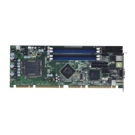
- Page 1 SHB102 Series ™ ™ ® Intel Core 2 Quad/Core 2 Duo ® Celeron Processor PICMG 1.3 Full-Size Single Board Computer User’s Manual...
- Page 2 AXIOMTEK does not warrant or assume any legal liability or responsibility for the accuracy, completeness or usefulness of any information in this document. AXIOMTEK does not make any commitment to update the information in this manual.
-
Page 3: Esd Precautions
Wear a wrist-grounding strap, available from most electronic component stores, when handling boards and components. Trademarks Acknowledgments AXIOMTEK is a trademark of AXIOMTEK Co., Ltd. ® Windows is a trademark of Microsoft Corporation. AMI are trademarks of American Megatrend Inc. -
Page 4: Table Of Contents
Table of Contents Disclaimers ......................ii ESD Precautions ....................iii CHAPTER 1 INTRODUCTION ................... 1 Specifications ..................2 Utilities Supported ................. 4 I/O Bracket .................... 4 CHAPTER 2 JUMPERS AND CONNECTORS ............5 Board Dimensions ................. 5 Board Layout ..................6 Jumper Settings .................. - Page 5 Interrupt Controller (IRQ) Map ............. 29 CHAPTER 5 AMI BIOS UTILITY ................31 Starting ....................31 Navigation Keys .................. 31 Main Menu ..................33 Advanced Menu .................. 34 PCI PnP Menu..................49 Boot Menu ................... 51 Security Menu ..................55 Chipset Menu ..................
- Page 6 MEMO...
-
Page 7: Chapter 1 Introduction
SHB102 LGA775 Full-Size SBC User’s Manual CHAPTER 1 INTRODUCTION The SHB102 PICMG 1.3 full-size Single Board Computer supports ® ® ™ ™ LGA775 socket for Intel Core 2 Quad / Core 2 Duo/Celeron processors with 45/65nm technology and FSB 800/1066/1333 MHz. ®... -
Page 8: Specifications
SHB102 LGA775 Full-Size SBC User’s Manual Specifications ® ® ™ ™ Intel Core 2 Quad / Core 2 Duo/Celeron processors System Chipset ® Intel Q45 and ICH10DO CPU Socket LGA775 Socket Front-Side Bus ... - Page 9 SHB102 LGA775 Full-Size SBC User’s Manual memory for frame buffer option as 32/48/64/128/256MB, and 96 MB (0 + 96), 160 MB (64 + 96), 224 MB (128 + 96), 352 MB (256 + 96). Resolution -- Analog output -- the analog port utilizes an integrated 350MHz 24-bit RAMDAC that can directly drive a standard progressive scan analog monitor up to a resolution of 2048x1536 pixels with 32-bit color at 75 Hz...
-
Page 10: Utilities Supported
SHB102 LGA775 Full-Size SBC User’s Manual Utilities Supported ® Intel Q45 Utility and Drivers VGA Drivers Ethernet Utility and Drivers RAID Utility iAMT Utility and Drivers ITPM Utility I/O Bracket Introduction... -
Page 11: Chapter 2 Jumpers And Connectors
SHB102 LGA775 Full-Size SBC User’s Manual CHAPTER 2 JUMPERS AND CONNECTORS Board Dimensions Jumpers and Connectors... -
Page 12: Board Layout
SHB102 LGA775 Full-Size SBC User’s Manual Board Layout CN22 CN30 CN29 Jumpers and Connectors... -
Page 13: Jumper Settings
SHB102 LGA775 Full-Size SBC User’s Manual Jumper Settings Proper jumper settings configure the SHB102 to meet your application purpose. 2.3.1 COM2 Mode Select Jumpers for RS-232/422/485 (JP7, JP6, JP5) These jumpers select the COM2 port‟s communication mode to operate RS-232 or RS-422/485. Description Function Jumper Setting COM2... -
Page 14: Cmos Clear Jumper (Jp13)
SHB102 LGA775 Full-Size SBC User’s Manual 2.3.2 CMOS Clear Jumper (JP13) You may need to use this jumper is to clear the CMOS memory if incorrect BIOS settings. Description Function Jumper Setting CMOS Clear Normal (Default) Clear CMOS 2.3.3 ATX Auto Power On/Off (JP1) When Jumper JP1 is set OPEN for AC power input, the system will be automatically power ON without pressing soft power button;... -
Page 15: Me Clear Jumper (Jp14)
SHB102 LGA775 Full-Size SBC User’s Manual 2.3.4 ME Clear Jumper (JP14) Description Function Jumper Setting Normal ME Clear (Default) Clear CMOS 2.3.5 ME Disable/Enable Jumper (JP9) Description Function Jumper Setting Enable ME Disable/ (Default) Enable Disable Jumpers and Connectors... -
Page 16: Tpm Disable/Enable Jumper (Jp10)
SHB102 LGA775 Full-Size SBC User’s Manual 2.3.6 TPM Disable/Enable Jumper (JP10) Description Function Jumper Setting Enable (Default) Disable/ Enable Disable 2.3.7 Audio Amplifier Jumper (JP11) Description Function Jumper Setting Disable Audio Amplifier Enable (Default) Jumpers and Connectors... -
Page 17: Connectors
SHB102 LGA775 Full-Size SBC User’s Manual Connectors Connectors connect this board with other parts of the system. Loose or improper connection might cause problems. Make sure all connectors are properly and firmly connected. Here is a summary table shows you all connectors on the board. Connector Label Connector... -
Page 18: Atx 4 Pin 12V In Connector (Cn4)
SHB102 LGA775 Full-Size SBC User’s Manual 2.4.1 ATX 4 Pin 12V In Connector (CN4) You can connect it to the ATX12V power supply for CPU Core Voltage. Signal +12V +12V 2.4.2 Front Panel Connector (CN2) Power LED This 3-pin connector denoted as Pin 1 and Pin 5 connects the system power LED indicator to such a switch on the case. -
Page 19: Lan1 Led Connectors (Cn20)
SHB102 LGA775 Full-Size SBC User’s Manual that reboots your computer instead of turning OFF the power switch. It is a better way to reboot your system for a longer life of the system‟s power supply. HDD Activity LED This connection is linked to hard drive activity LED on the control panel. -
Page 20: Com Port Rs-232 Pin Assignment (Cn5, Cn9)
SHB102 LGA775 Full-Size SBC User’s Manual 2.4.5 COM Port RS-232 Pin Assignment (CN5, CN9) The serial interface for the board consists of CN5 port (COM1) support for RS-232, and CN9 (COM2) for RS-232/RS422/RS485. Signal Signal Data Carrier Detect Data Set Ready (DSR) (DCD) Receive Data (RXD) Request to Send (RTS) -
Page 21: Cpu Fan Connector (Cn32)
SHB102 LGA775 Full-Size SBC User’s Manual 2.4.7 CPU Fan Connector (CN32) A CPU fan is always needed for cooling CPU heat. The CPU fan connector FAN32 provides power to the CPU fan. Signal 1 Ground 2 +12V 3 Rotation Detection 4 Speed Control 2.4.8 System Fan Connectors (CN33, CN34) -
Page 22: Intel ® Hd Audio Digital Header (Cn24)
SHB102 LGA775 Full-Size SBC User’s Manual Signal Signal Signal 28 Write protect# 29 No connector 30 Read data# 31 GND 32 Head selection# 33 No connector 34 Disk change# ® 2.4.10 Intel HD Audio Digital Header (CN24) Signal Signal BCLK RST# VCC3 SYNC... -
Page 23: Ps/2 Keyboard, Mouse Connectors (Cn29, Cn30)
SHB102 LGA775 Full-Size SBC User’s Manual 2.4.11 PS/2 Keyboard, Mouse Connectors (CN29, CN30) The board provides the Keyboard (CN29)/ Mouse (CN30) interface with a 5-pin connector. Signal Clock DATA No connector 2.4.12 Ethernet RJ-45 Connectors (CN11, CN16) The RJ-45 connectors LAN1 and LAN2 are for Ethernet. To connect the board to 100-Base-T or 1000-Base-T hub, just plug one end of the cable into LAN1 and connect the other end (phone jack) to a 100-Base- T hub or 1000-Base-T hub. -
Page 24: Parallel Port Connector (Cn6)
SHB102 LGA775 Full-Size SBC User’s Manual 2.4.13 Parallel Port Connector (CN6) Print Port Connector [Default] This board has a multi-mode parallel port to support: 1. Standard Mode: IBM PC/XT, PC/AT and PS/2 are compatible with bi-directional parallel port. 2. Enhanced Mode: Enhance parallel port (EPP) is compatible with EPP 1.7 and EPP 1.9 (IEEE 1284 compliant). -
Page 25: Sata Connectors (Cn13, Cn14, Cn15, Cn17, Cn18, Cn19)
SHB102 LGA775 Full-Size SBC User’s Manual 2.4.14 SATA Connectors (CN13, CN14, CN15, CN17, CN18, CN19) These SATA connectors are for high-speed SATA interface ports and they can be connected to hard disk devices. Signal SATA_TX+ SATA_TX- SATA_RX- SATA_RX+ 2.4.15 USB Connectors (CN21, CN23, CN25) The 10-pin standard Universal Serial Bus (USB) connectors, CN21/23/25, on this board are for installing versatile USB interface peripherals. -
Page 26: Usb Port Connectors (Cn27, Cn31)
SHB102 LGA775 Full-Size SBC User’s Manual Signal Signal CN25 1 USB 3 USB4- USB5- 5 USB4+ USB5+ 7 GND 10 GND 2.4.16 USB Port Connectors (CN27, CN31) The 4-pin standard Universal Serial Bus (USB) port connector on the board is for the installation of peripherals supporting the USB interface. CN27 Signal USB POWER... -
Page 27: Chapter 3 Hardware Installation
SHB102 LGA775 Full-Size SBC User’s Manual CHAPTER 3 HARDWARE INSTALLATION ® Before installing the processor, please access Intel website for more detailed information http://www.intel.com . Installing the Processor The LGA775 processor socket comes with a cover to protect the processor. Please install the processor into the CPU socket step by step as below: Hold the hook (A) of the lever and push it down. - Page 28 SHB102 LGA775 Full-Size SBC User’s Manual Open the cover (C), you can Be careful not to touch the see the contact. contact (D). Remove the plastic cap (E) from the cover. Hardware Installation...
- Page 29 SHB102 LGA775 Full-Size SBC User’s Manual Place the CPU down into the socket. Be careful not to touch the contact. Hold the edges of the CPU, and orientate it as the marked direction (G) down into the socket to match the (H) and (F) locations. Hardware Installation...
- Page 30 SHB102 LGA775 Full-Size SBC User’s Manual Slightly push down the cover and hook the lever (I~J). The CPU is completely locked. Orientate the CPU cooling fan to fixing holes on the board. Hardware Installation...
- Page 31 SHB102 LGA775 Full-Size SBC User’s Manual Screw the CPU cooling fan onto the board. Make sure the CPU fan is plugged to the CPU fan connector. Hardware Installation...
-
Page 32: Installing The Memory
SHB102 LGA775 Full-Size SBC User’s Manual Installing the Memory The board supports four 240-pin DDR3 DIMM memory sockets with maximum memory capacity up to 16GB. Please follow steps below to install the memory modules: Push down latches on each side of the DIMM socket. Align the memory module with the socket that notches of memory module must match the socket keys for a correct installation. -
Page 33: Chapter 4 Hardware Description
CPU from damages. BIOS The SHB102 Series uses AMI Plug and Play BIOS with a single 32Mbit SPI Flash. System Memory The SHB102 Series supports four 240-pin DDR3 DIMM sockets for a maximum memory of 16GB DDR3 SDRAMs. -
Page 34: I/O Port Address Map
SHB102 LGA775 Full-Size SBC User’s Manual I/O Port Address Map ® ® ™ ™ Core™2 Extreme/ The Intel Intel Core 2 Quad / Core ® Duo/Celeron CPUs can communicate via I/O ports. There are total 1KB port addresses available for assignment to other devices via I/O expansion cards. -
Page 35: Interrupt Controller (Irq) Map
Serial port #2 (COM2) Interrupt Controller (IRQ) Map The SHB102 Series is a 100% PC compatible control board. It consists of 16 interrupt request lines, and four out of them can be programmable. The mapping list of the 16 interrupt request lines is shown as the following table. - Page 36 SHB102 LGA775 Full-Size SBC User’s Manual MEMO Hardware Description...
-
Page 37: Chapter 5 Ami Bios Utility
SHB102 LGA775 Full-Size SBC User’s Manual CHAPTER 5 AMI BIOS UTILITY This chapter provides users with detailed description how to set up basic system configuration through the AMIBIOS8 BIOS setup utility. Starting To enter the setup screens, follow the steps below: Turn on the computer and press the <Del>... - Page 38 SHB102 LGA775 Full-Size SBC User’s Manual The Left <Arrow> keys allow you to select a setup Left/Right screen. The Up and Down <Arrow> keys allow you to select Up/Down a setup screen or sub-screen. The Plus and Minus <Arrow> keys allow you to +...
-
Page 39: Main Menu
SHB102 LGA775 Full-Size SBC User’s Manual Main Menu When you first enter the Setup Utility, you will enter the Main setup screen. You can always return to the Main setup screen by selecting the Main tab. There are two Main Setup options. They are described in this section. -
Page 40: Advanced Menu
SHB102 LGA775 Full-Size SBC User’s Manual Advanced Menu The Advanced menu allows users to set configuration of the CPU and other system devices. You can select any of the items in the left frame of the screen to go to the sub menus: ... - Page 41 SHB102 LGA775 Full-Size SBC User’s Manual CPU Configuration This screen shows the CPU Configuration, and you can change the value of the selected option. Hardware Prefetcher This item automatically analyzes its requirements and prefetches data and instructions from the memory. When enabled, the processor‟s hardware prefetcher will be allowed to automatically prefetch data and code for the processor.
- Page 42 SHB102 LGA775 Full-Size SBC User’s Manual Max CPUID Value Limit You can enable this item to let legacy operating systems boot even without support for CPUs with extended CPU ID functions. Execute-Disable Bit Capability This item helps you enable or disable the No-Execution Page Protection Technology.
- Page 43 SHB102 LGA775 Full-Size SBC User’s Manual SATA#1 Configuration Use this item to control the onboard SATA controller. Here are the options for your selection, Compatible, Disabled, and Enhanced. Configure SATA#1 as Use this item to choose the SATA operation mode. Here are the options for your selection, IDE and AHCI.
- Page 44 SHB102 LGA775 Full-Size SBC User’s Manual Floppy Configuration You can use this screen to select options for the Floppy Configuration, and change the value of the selected option. A description of the selected item appears on the right side of the screen.
- Page 45 SHB102 LGA775 Full-Size SBC User’s Manual SuperIO Configuration You can use this screen to select options for the SuperIO Configuration, and change the value of the selected option. A description of the selected item appears on the right side of the screen.
- Page 46 SHB102 LGA775 Full-Size SBC User’s Manual onboard parallel port. There are several options for your selection. Parallel Port Mode Select an operating mode for the onboard parallel (printer) port. Parallel Port IRQ Use this item to set up the IRQ for onboard parallel port. ...
- Page 47 SHB102 LGA775 Full-Size SBC User’s Manual ACPI Configuration You can use this screen to select options for the ACPI Configuration, and change the value of the selected option. A description of the selected item appears on the right side of the screen.
- Page 48 SHB102 LGA775 Full-Size SBC User’s Manual Interface) options for your configuration. AHCI Configuration You can use this screen to select options for the AHCI Configuration, and change the value of the selected option. A description of the selected item appears on the right side of the screen.
- Page 49 SHB102 LGA775 Full-Size SBC User’s Manual Intel iAMT Configuration You can use this screen to select options for the Intel iAMT Configuration, and change the value of the selected option. A description of the selected item appears on the right side of the screen.
- Page 50 SHB102 LGA775 Full-Size SBC User’s Manual Intel VT-d Configuration You can use this screen to select options for the Intel VT-d Configuration, and change the value of the selected option. A description of the selected item appears on the right side of the screen.
- Page 51 SHB102 LGA775 Full-Size SBC User’s Manual MPS Configuration This screen shows the MPS (Multi Processor Specification) Configuration, and you can change its value. A description of the selected item appears on the right side of the screen. MPS Revision Use this item to select MPS (Multi Processor Specification) Revision 1.1 or 1.4.
- Page 52 SHB102 LGA775 Full-Size SBC User’s Manual PCI Express Configuration This screen shows the PCI Express Configuration, and you can change its value. A description of the selected item appears on the right side of the screen. Active State Power-Management Use this item to enable or disable the function of Active State Power-Management to provide you with lower power consumption.
- Page 53 SHB102 LGA775 Full-Size SBC User’s Manual Trusted Computing You can use this screen to select options for the Trusted Computing, and change the value of the selected option. A description of the selected item appears on the right side of the screen.
- Page 54 SHB102 LGA775 Full-Size SBC User’s Manual USB Configuration You can use this screen to select options for the USB Configuration, and change the value of the selected option. A description of the selected item appears on the right side of the screen. ...
-
Page 55: Pci Pnp Menu
SHB102 LGA775 Full-Size SBC User’s Manual PCI PnP Menu The PCI PnP menu allows users to change the advanced settings for PCI/PnP devices. Clear NVRAM Use this item to clear the data in the NVRAM (CMOS). Here are the options for your selection, No and Yes. ... - Page 56 SHB102 LGA775 Full-Size SBC User’s Manual PCI Latency Timer This item controls how long a PCI device can hold the PCI bus before another takes over. The longer the latency, the longer the PCI device can retain control of the bus before handing it over to another PCI device.
-
Page 57: Boot Menu
SHB102 LGA775 Full-Size SBC User’s Manual Boot Menu The Boot menu allows users to change boot options of the system. You can select any of the items in the left frame of the screen to go to the sub menus: ... - Page 58 SHB102 LGA775 Full-Size SBC User’s Manual Boot Settings Configuration Quick Boot Enabling this item lets the BIOS skip some power on self tests (POST). The default setting is Enabled. AddOn ROM Display Mode This item selects the display mode for option ROM. The default setting is Force BIOS.
- Page 59 SHB102 LGA775 Full-Size SBC User’s Manual “Press DEL to run Setup” during POST. The default setting is Enabled. Interrupt 19 Capture If this item is enabled, this function makes the option ROMs to trap Interrupt 19. The default setting is Disabled. ...
- Page 60 SHB102 LGA775 Full-Size SBC User’s Manual Removable Drives Use this screen to view the removable drives in the system. The BIOS will attempt to arrange the removable drive boot sequence automatically. You can also change the booting sequence. AMI BIOS Utility...
-
Page 61: Security Menu
SHB102 LGA775 Full-Size SBC User’s Manual Security Menu The Security menu allows users to change the security settings for the system. Supervisor Password This item indicates whether a supervisor password has been set. If the password has been installed, Installed displays. -
Page 62: Chipset Menu
SHB102 LGA775 Full-Size SBC User’s Manual Chipset Menu The Chipset menu allows users to change the advanced chipset settings. You can select any of the items in the left frame of the screen to go to the sub menus: North Bridge Configuration ... - Page 63 SHB102 LGA775 Full-Size SBC User’s Manual North Bridge Configuration Memory Remap Feature Use this item to enable or disable the remapping of the overlapped PCI memory above the total physical memory. Only 64-bit OS supports this function. DRAM Frequency This item allows you to control the Memory Clock.
- Page 64 SHB102 LGA775 Full-Size SBC User’s Manual Initiate Graphic Adapter When using multiple graphics cards, this item can select which graphics controller to be the primary display device during boot. IGD Graphics Mode Select This item allows you to select the amount of system memory used by the internal graphics device.
- Page 65 SHB102 LGA775 Full-Size SBC User’s Manual South Bridge Configuration USB Function This item allows you to enable or disable USB function. GbE LAN Boot This item allows you to enable or disable the LAN controller. GbE Wake Up From S5 This item specifies whether the system will be awakened from the S5 power.
- Page 66 SHB102 LGA775 Full-Size SBC User’s Manual PCIE Port Configuration This item allows you to set or disable the PCI Express Ports. ME Subsystem Configuration It is strongly recommended that you do not modify these options unless you are an advanced user. AMI BIOS Utility...
-
Page 67: Exit Menu
SHB102 LGA775 Full-Size SBC User’s Manual Exit Menu The Exit menu allows users to load your system configuration with optimal or failsafe default values. Save Changes and Exit When you have completed the system configuration changes, select this option to leave Setup and reboot the computer so the new system configuration parameters can take effect. - Page 68 SHB102 LGA775 Full-Size SBC User’s Manual computer is experiencing system configuration problems. Select Load Optimal Defaults from the Exit menu and press <Enter>. Load Fail-Safe Defaults It automatically sets all Setup options to a complete set of default settings when you select this option. The Fail-Safe settings are designed for maximum system stability, but not maximum performance.
-
Page 69: Chpater 6 Installation Of Drivers
INSTALLATION OF DRIVERS The device drivers are located on the Product Information CD-ROM that comes with the SHB102 Series package. The auto-run function of drivers will guide you to install the utilities and device drivers under a Windows system. You can follow the onscreen instructions to install these devices: ... - Page 70 SHB102 LGA775 Full-Size SBC User’s Manual ® An Intel License Agreement appears to show you the important information. Click “Yes” to next step. 3. Refer to the Readme file below to view the system requirements and installation information. Installation of Drivers...
- Page 71 SHB102 LGA775 Full-Size SBC User’s Manual 3-1 Please wait while running the following setup operations. 3-2 Please wait while running the following setup operations. Installation of Drivers...
- Page 72 SHB102 LGA775 Full-Size SBC User’s Manual Click “Finish” to complete the setup process. You will be asked to reboot your computer when the installation is completed. Please click “Yes, I want to restart my computer now” if you don‟t need to install any other drivers.
-
Page 73: Installing Vga Driver
SHB102 LGA775 Full-Size SBC User’s Manual Installing VGA Driver 1. Run the SETUP.EXE program from the driver directory in your driver CD. Click “Next” to next step. ® An Intel License Agreement appears to show you the important information. Click “Yes” to next step. Installation of Drivers... - Page 74 SHB102 LGA775 Full-Size SBC User’s Manual The message of Readme File Information appears to show you the system requirements and installation information. Please click “Next”. Please wait while running the following setup operations. When this message appears, please click “Next”. Installation of Drivers...
- Page 75 SHB102 LGA775 Full-Size SBC User’s Manual Click “Finish” to complete the setup process. You will be asked to reboot your computer when the installation is completed. Please click “Yes, I want to restart my computer now” if you don‟t need to install any other drivers.
-
Page 76: Installing Lan Driver
SHB102 LGA775 Full-Size SBC User’s Manual Installing LAN Driver 1.1 Run the InstallShield Wizard for Network Connections from the driver directory in your driver CD. Click “Next” to next step. Installation of Drivers... - Page 77 SHB102 LGA775 Full-Size SBC User’s Manual ® 1.2 An Intel License Agreement appears to show you the important information. Click “Yes” to next step. 1.3 A Setup Options window appears that you can select the program features you want to install. Installation of Drivers...
- Page 78 SHB102 LGA775 Full-Size SBC User’s Manual Click “Install” to start the installation. Please wait while running the following installation operation. Installation of Drivers...
- Page 79 SHB102 LGA775 Full-Size SBC User’s Manual Click “Finish” to complete the installation. Note The Driver item [Wake on Directed Packet] default is Enabled under Windows Vista. Installation of Drivers...
-
Page 80: Installing Audio Driver
SHB102 LGA775 Full-Size SBC User’s Manual Installing AUDIO Driver Run the InstallShield Wizard for Realtek High Definition Audio Driver from the driver directory in your driver CD. Click “Next” to next step. Installation of Drivers... - Page 81 SHB102 LGA775 Full-Size SBC User’s Manual Click “Install” to start the installation, and wait while running the installation operation. Click “Finish” to complete the installation. Installation of Drivers...
-
Page 82: Installing Iamt (Active Management Technology) Driver
SHB102 LGA775 Full-Size SBC User’s Manual Installing iAMT (Active Management Technology) Driver Note You must download and properly install the required .NET version 3.5 provided from a separate downloading of the actual Fimware/Tools kit releases posted on VIP prior to loading the MEI/LMS Driver stack. - Page 83 SHB102 LGA775 Full-Size SBC User’s Manual ® 2. An Intel license agreement appears that you need to continue the setup program by clicking “Yes” to accept the terms. Installation of Drivers...
- Page 84 SHB102 LGA775 Full-Size SBC User’s Manual 3. Refer to the Readme file below to view the system requirements and installation information. Click “Next” to next setup. 4. Please wait while running the following installation operation. Installation of Drivers...
- Page 85 SHB102 LGA775 Full-Size SBC User’s Manual Click “Finish” to complete the installation. Installation of Drivers...
-
Page 86: Lms_Sol_Is Setup
SHB102 LGA775 Full-Size SBC User’s Manual 6.5.2 LMS_SOL_IS Setup ® Run the setup program to install Intel Active Management Technology onto your computer. It is strongly recommended that you exit all programs before continuing. Click “Next” to next step. Installation of Drivers... - Page 87 SHB102 LGA775 Full-Size SBC User’s Manual ® An Intel license agreement appears that you need to continue the setup program by clicking “Yes” to accept the terms. Installation of Drivers...
- Page 88 SHB102 LGA775 Full-Size SBC User’s Manual 3. Refer to the Readme file below to view the system requirements and installation information. Click “Next” to next setup. 4. Please wait while running the following installation operation. Installation of Drivers...
- Page 89 SHB102 LGA775 Full-Size SBC User’s Manual Click “Finish” to complete the installation. Installation of Drivers...
-
Page 90: Installing Mei (Management Engine Interface) Driver
SHB102 LGA775 Full-Size SBC User’s Manual Installing MEI (Management Engine Interface) Driver Note You must download and properly install the required .NET version 3.5 provided from a separate downloading of the actual Fimware/Tools kit releases posted on VIP prior to loading the MEI/LMS Driver stack. - Page 91 SHB102 LGA775 Full-Size SBC User’s Manual ® 2. An Intel license agreement appears that you need to continue the setup program by clicking “Yes” to accept the terms. Installation of Drivers...
- Page 92 SHB102 LGA775 Full-Size SBC User’s Manual 3. Refer to the Readme file below to view the system requirements and installation information. Click “Next” to next setup. 4. Please wait while running the following installation operation. Installation of Drivers...
- Page 93 SHB102 LGA775 Full-Size SBC User’s Manual Click “Finish” to complete the installation. Installation of Drivers...
- Page 94 SHB102 LGA775 Full-Size SBC User’s Manual MEMO Installation of Drivers...
-
Page 95: Appendix A Watchdog Timer
SHB102 LGA775 Full-Size SBC User’s Manual APPENDIX A WATCHDOG TIMER Watchdog Timer Setting After the system stops working for a while, it can be auto-reset by the Watchdog Timer. The integrated Watchdog Timer can be set up in the system reset mode by program. Using the Watchdog Function Start ... - Page 96 SHB102 LGA775 Full-Size SBC User’s Manual IF No re-set timer :WDT time-out, generate RESET IF to disable WDT :O 2E 30 O 2F 00 ; Can be disable at any time N=00 M= 00h: Time-out Disable 01h: Time-out occurs after 1 second 02h: Time-out occurs after 2 second 03h: Time-out occurs after 3 second ………………………........
-
Page 97: Appendix Bpci Irq Routing
SHB102 LGA775 Full-Size SBC User’s Manual APPENDIX B PCI IRQ ROUTING PICMG PCI IRQ Routing Device Slot PCI Slot 0 BCDA PCI Slot 1 CDAB PCI Slot 2 DABC PCI Slot 3 ABCD PCI IRQ Routing... - Page 98 SHB102 LGA775 Full-Size SBC User’s Manual MEMO PCI IRQ Routing...
-
Page 99: Appendix C Configuring Sata For Raid Function
SHB102 LGA775 Full-Size SBC User’s Manual APPENDIX C CONFIGURING SATA FOR RAID FUNCTION Configuring SATA Hard Drive(s) for RAID ® Function (Controller: Intel ICH10DO/DO DH only) Please follow up the steps below to configure SATA hard drive(s): (1) Install SATA hard drive(s) in your system. (2) Enter the BIOS Setup to configure SATA controller mode and boot sequence. - Page 100 SHB102 LGA775 Full-Size SBC User’s Manual (2)-1-1 Turn on your system, and then press the Del button to enter BIOS Setup during running POST (Power-On Self Test). If you want to create RAID, just go to the Advanced Settings menu/IDE configuration, select the Configure SATA#1 as, and press <Enter>...
- Page 101 SHB102 LGA775 Full-Size SBC User’s Manual (2)-1-2 A list of options appears, please select RAID. Configuring SATA for RAID Function...
- Page 102 SHB102 LGA775 Full-Size SBC User’s Manual (2)-2 Set CDROM for First Boot Device under the Boot Settings menu to boot CD-ROM after system restarts. (2)-3 Save and exit the BIOS Setup. Configuring SATA for RAID Function...
- Page 103 SHB102 LGA775 Full-Size SBC User’s Manual (3) Configuring RAID by the RAID BIOS Enter the RAID BIOS setup utility to configure a RAID array. Skip this step and proceed to Section 4 if you do not want to create a RAID. (3)-1 After the POST memory testing and before the operating system booting, a message "Press <Ctrl-I>...
- Page 104 SHB102 LGA775 Full-Size SBC User’s Manual (3)-3-1 After entering the CREATE VOLUME MENU screen, you can type the disk array name with 1~16 letters (letters cannot be special characters) in the item “Name”. (3)-3-2 When finished, press ENTER to select a RAID level. There are three RAID levels, RAID0, RAID1 and RAID5 &...
- Page 105 SHB102 LGA775 Full-Size SBC User’s Manual (3)-4 Set the stripe block size. The KB is the standard unit of stripe block size. The stripe block size can be 4KB to 128KB. After the setting, press ENTER for the array capacity. (3)-5 After setting all the items on the menu, select Create Volume and press ENTER to start creating the RAID array.
- Page 106 SHB102 LGA775 Full-Size SBC User’s Manual When prompting the confirmation, press “Y“ to create this (3)-6 volume, or “N“ to cancel the creation. After the creation is completed, you can see detailed information about the RAID Array in the DISK/VOLUME INFORMATION section, including RAID mode, disk block size, disk name, and disk capacity, etc.
- Page 107 SHB102 LGA775 Full-Size SBC User’s Manual Delete RAID Volume If you want to delete a RAID volume, select the Delete RAID Volume option in Main Menu. Press ENTER and follow on-screen instructions. Please press [ESC] to exit the RAID BIOS utility. Now, you can proceed to install a SATA driver controller and the operating system.
- Page 108 SHB102 LGA775 Full-Size SBC User’s Manual (4) Making a SATA Driver Disk To install the operating system onto a serial ATA hard disk successfully, you need to install the SATA controller driver during the OS installation. Without the driver, the hard disk may not be recognized during the Windows setup process.
- Page 109 SHB102 LGA775 Full-Size SBC User’s Manual (5) Installing the SATA controller driver during the OS installation Now, the SATA driver disk is ready, and BIOS settings configured, you can proceed to install Windows 2000/XP onto your SATA hard drive using the SATA driver. Here is an example for Windows XP installation. (5)-1 Restart your system to boot the Windows 2000/XP Setup disk, and press F6 button as soon as you see the message "Press...
- Page 110 SHB102 LGA775 Full-Size SBC User’s Manual (5)-2 When you see the screen below, insert the floppy disk containing the SATA driver and press “S”. (5)-3 If the Setup correctly recognizes the driver of the floppy disk, a controller menu will appear below. Use the ARROW keys to select Intel(R) ICH8R/ICH9R/ICH10R/DO SATA RAID Controller and press ENTER.
- Page 111 SHB102 LGA775 Full-Size SBC User’s Manual Note If a message on the screen saying that one or some file(s) cannot be found, please check the floppy disk or copy the correct SATA driver again from the driver CD. Configuring SATA for RAID Function...
- Page 112 SHB102 LGA775 Full-Size SBC User’s Manual MEMO Configuring SATA for RAID Function...
-
Page 113: Appendix D Iamt Settings
SHB102 LGA775 Full-Size SBC User’s Manual APPENDIX D iAMT SETTINGS ® ® The Intel Active Management Technology (Intel iAMT) has decreased a major barrier to IT efficiency that uses built-in platform capabilities and popular third-party management and security applications to allow IT a better discovering, healing, and protection their networked computing assets. -
Page 114: D.2 Set & Change Password
SHB102 LGA775 Full-Size SBC User’s Manual D.2 Set & Change Password 1. You will be asked to set a password when first log in. The default password is „admin‟. Change Password 2. You will be asked to change the password before setting ME. iAMT Settings... - Page 115 SHB102 LGA775 Full-Size SBC User’s Manual 3. You must confirm your new password while revising. (as Remark 1) Remark 1 The new password must contain: (example: !!11qqQQ) (default value) Eight characters One upper case One lower case One number ...
-
Page 116: Intel Iamt Settings
SHB102 LGA775 Full-Size SBC User’s Manual ® D.3 Intel iAMT Settings ® Select Intel iAMT Configuration and press <ENTER>. ® iAMT set to „DHCP„, the Host name Key in the Host Name. If Intel must be identical to the operating system mechanic. iAMT Settings... - Page 117 SHB102 LGA775 Full-Size SBC User’s Manual Select TCP/IP to get into Network interface, and set it to „ENABLED‟; into DHCP Mode, and set it to „DISABLED‟ (as Remark 2) ; into Domain name, and set the Intel Management Engine domain name, such as „AMT.intel.com‟. (3-1) (3-2) iAMT Settings...
- Page 118 SHB102 LGA775 Full-Size SBC User’s Manual DHCP Mode ‘DISABLED‘: if DHCP Mode is Remark 2 disabled, you can make the following settings: IP address Subnet mask iAMT Settings...
- Page 119 SHB102 LGA775 Full-Size SBC User’s Manual Default Gateway address Preferred DNS address iAMT Settings...
- Page 120 SHB102 LGA775 Full-Size SBC User’s Manual Alternate DNS address Domain name Exit from MEBx after completing the iAMT settings. iAMT Settings...
-
Page 121: D.4 Iamt Web Console
SHB102 LGA775 Full-Size SBC User’s Manual D.4 iAMT Web Console From a web browser, please type http://(IP ADDRESS):16992, which connects to iAMT Web. Example: http://10.1.40.214:16992 To log on, you will be required to type in username and password for access to the Web. USER: admin (default value) PASS: (MEBx password) iAMT Settings... - Page 122 SHB102 LGA775 Full-Size SBC User’s Manual Enter the iAMT Web. Click Remote Control, and select commands on the right side. iAMT Settings...
- Page 123 SHB102 LGA775 Full-Size SBC User’s Manual 5. When you have finished using the iAMT Web console, close the Web browser. iAMT Settings...
- Page 124 SHB102 LGA775 Full-Size SBC User’s Manual MEMO iAMT Settings...
-
Page 125: Appendix E Picmg V1.3 Interface Definition
SHB102 LGA775 Full-Size SBC User’s Manual APPENDIX E PICMG v1.3 INTERFACE DEFINITION x16 PCIe Connector A x16 PCIe Connector C Side B Side A Side B Side A 1 N.C 1 USB0P 2 GND 2 USB0N 3 N.C 3 GND USB1P 4 N.C 4 GND... - Page 126 SHB102 LGA775 Full-Size SBC User’s Manual Mechanical Key 29 REFCLK0+ 29 N.C 30 REFCLK0- 30 N.C 31 GND REFCLK1+ 31 N.C 32 RSVD REFCLK1- 32 N.C 33 REFCLK2+ 33 N.C 34 REFCLK2- 34 N.C 35 GND REFCLK3+ 35 N.C 36 RSVD REFCLK3- 36 GND 37 REFCLK4+...
- Page 127 SHB102 LGA775 Full-Size SBC User’s Manual Mechanical Key 64 GND a_PERn4 64 GND 65 a_PETp5 65 GND 66 a_PETn5 66 GND 67 GND a_PERp5 67 GND 68 GND a_PERn5 68 GND 69 a_PETp6 69 GND 70 a_PETn6 70 GND 71 GND a_PERp6 71 GND 72 GND...
- Page 128 SHB102 LGA775 Full-Size SBC User’s Manual Mechanical Key 12 GND 12 CLKC CLKD 13 a_PETp10 13 GND +3.3V 14 a_PETn10 14 CLKA CLKB 15 GND a_PERp10 15 +3.3V 16 GND a_PERn10 16 AD31 17 a_PETp11 17 AD29 +3.3V 18 a_PETn11 18 N.C AD30 19 GND...
- Page 129 SHB102 LGA775 Full-Size SBC User’s Manual 47 +12V +12V 47 GND AD02 Mechanical Key 48 +12V +12V 48 AD03 AD01 49 +12V +12V 49 AD00 Note Please contact your vendor to get the backplane design guide if it’s required. The backplane design guide is NDA required.
- Page 130 SHB102 LGA775 Full-Size SBC User’s Manual MEMO PICMG v1.3 Interface Definition...