Table of Contents
Advertisement
Quick Links
Product User Manual
and enterprise branch and head offices
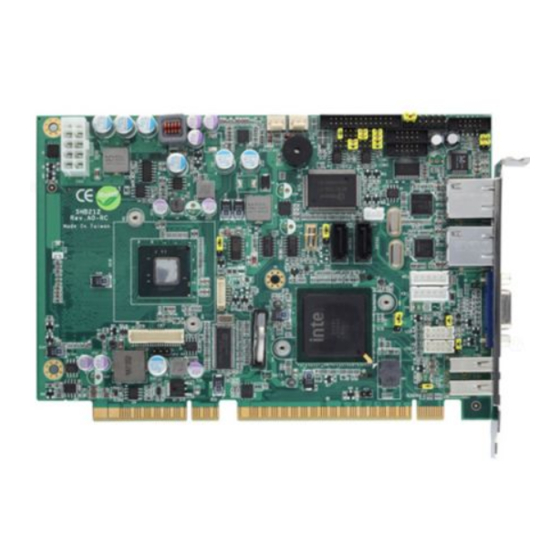
SHB212
www.enochsystems.com
1-877-722-1116
sales@enochsystems.com
Copyright © 2013 Enoch Systems, LLC, Enoch Systems and the Enoch Systems logo are trademarks or registered trademarks of Enoch Systems, LLC and/or its affiliates in the U.S. and other countries.
Third-party trademarks mentioned are the property of their respective owners. All rights reserved.
Advertisement
Table of Contents

Related Manuals for AXIOMTEK SHB212 Series


Summary of Contents for AXIOMTEK SHB212 Series
- Page 1 Product User Manual and enterprise branch and head offices SHB212 www.enochsystems.com 1-877-722-1116 sales@enochsystems.com Copyright © 2013 Enoch Systems, LLC, Enoch Systems and the Enoch Systems logo are trademarks or registered trademarks of Enoch Systems, LLC and/or its affiliates in the U.S. and other countries. Third-party trademarks mentioned are the property of their respective owners.
- Page 2 SHB212 Series Atom™ Processor Intel PICMG 1.3 Half-Size Single Board Computer User’s Manual...
- Page 3 Axiomtek does not make any commitment to update the information in this manual. Axiomtek reserves the right to change or revise this document and/or product at any time without notice. No part of this document may be reproduced, stored in a retrieval...
-
Page 4: Esd Precautions
Wear a wrist-grounding strap, available from most electronic component stores, when handling boards and components. Trademarks Acknowledgments Axiomtek is a trademark of Axiomtek Co., Ltd. ® Windows is a trademark of Microsoft Corporation. AMI is a registered of American Megatrends Inc. -
Page 5: Table Of Contents
Table of Contents CHAPTER 1 INTRODUTION ............1 1.1 Specifications ................ 2 1.2 Utilities Supported ..............3 CHAPTER 2 JUMPERS AND CONNECTORS ........ 5 2.1 Board Dimensions and Fixing Holes ........5 2.2 Board Layout ................. 7 2.3 Jumper Settings ..............9 2.3.1 COM1 RS-232/422/485 Mode Select (JP1, JP2, JP3) 10 2.3.2 COM1 Data / Power Mode Selection (JP6) .... - Page 6 3.1 Microprocessors ..............31 3.2 BIOS ................... 31 3.3 System Memory ..............31 3.4 I/O Port Address Map ............32 3.5 Interrupt Controller .............. 34 3.6 Memory Map ............... 36 CHAPTER 4 AMI BIOS UTILITY ............ 39 4.1 Starting ................39 4.2 Navigation Keys ..............
- Page 7 MEMO:...
-
Page 8: Chapter 1 Introdution
SHB212 PICMG1.3 Half-Size SBC User’s Manual CHAPTER 1 INTRODUCTION The SHB212 is a PICMG1.3 half-size Single Board Computer to support Intel® Atom™ processor N455/D425/D525. The board integrates chipset ICH8-M that delivers outstanding system performance through high-band width interfaces, multiple I/O functions interactive applications... -
Page 9: Specifications
SHB212 PICMG1.3 Half-Size SBC User’s Manual Specifications ® Intel Atom processor N455/D425/D525 System Chipset ® Intel ICH8M BIOS American Megatrends Inc. BIOS. 16Mbit SPI Flash PXE Ethernet Boot ROM. System Memory ... -
Page 10: Utilities Supported
SHB212 PICMG1.3 Half-Size SBC User’s Manual Expansion Interface One PCIe x4 or four PCIe x1 I/O Deivces There is no PCIex16 signal. Watchdog Timer 1~255 seconds; up to 255 levels Ethernet One port with INTEL 82567V for Gigabit/Fast Ethernet ... - Page 11 SHB212 PICMG1.3 Half-Size SBC User’s Manual MEMO INTRODUCTION...
-
Page 12: Chapter 2 Jumpers And Connectors
SHB212 PICMG1.3 Half-Size SBC User’s Manual CHAPTER 2 JUMPERS AND CONNECTORS Board Dimensions and Fixing Holes Top Side JUMPERS AND CONNECTORS... - Page 13 SHB212 PICMG1.3 Half-Size SBC User’s Manual Bottom Side JUMPERS AND CONNECTORS...
-
Page 14: Board Layout
SHB212 PICMG1.3 Half-Size SBC User’s Manual Board Layout Top Side JUMPERS AND CONNECTORS... - Page 15 SHB212 PICMG1.3 Half-Size SBC User’s Manual Bottom Side JUMPERS AND CONNECTORS...
-
Page 16: Jumper Settings
SHB212 PICMG1.3 Half-Size SBC User’s Manual Jumper Settings Proper jumer settings configure the SHB212 to meet your application purpose. We are here with listing a summary table of all jumpers and default settings for onboard devices, respectively. Jumper Description Jumper Setting COM1 RS-232/422/485 setting Short 1-2 Default:RS-232... -
Page 17: Com1 Rs-232/422/485 Mode Select (Jp1, Jp2, Jp3)
SHB212 PICMG1.3 Half-Size SBC User’s Manual 2.3.1 COM1 RS-232/422/485 Mode Select (JP1, JP2, JP3) These jumpers select the communication mode of COM1 port to operate RS-232 or RS-422 or RS-485. When these jumpers are selected to operate RS-422 or RS485, please make sure the COM1 is on Data mode. -
Page 18: Com1 Data / Power Mode Selection (Jp6)
SHB212 PICMG1.3 Half-Size SBC User’s Manual 2.3.2 COM1 Data / Power Mode Selection (JP6) The COM1 port have +5V or +12V level power capability on DCD and +5V or +12V level power capability for RI, depending on the JP6 setting. Function Jumper Setting COM1 Pin 1 is +12V level... -
Page 19: Com2 Data / Power Mode Selection (Jp5)
SHB212 PICMG1.3 Half-Size SBC User’s Manual 2.3.3 COM2 Data / Power Mode Selection (JP5) The COM2 port have +5V or +12V level power capability on DCD and +5V or +12V level power capability for RI, depending on the JP5 setting. Function Jumper Setting COM2 Pin 1 is +12V level... -
Page 20: Hd Audio Line Out / Speaker Out Select (Jp4)
SHB212 PICMG1.3 Half-Size SBC User’s Manual 2.3.4 HD Audio Line Out / Speaker Out Select (JP4) This jumper is to select which source for the audio output (CN3). When the Speaker Out is set, it delivers 2W/channel continuous into 8 Ohm loads. -
Page 21: Power On Control Mode (Jp8)
SHB212 PICMG1.3 Half-Size SBC User’s Manual 2.3.6 Power On Control Mode (JP8) The Power On Control mode provides two kinds of power on mode as follows, Function Jumper Setting Power On control by Front Panel Connector (Default) Power On control by Power Supply 2.3.7 USB0,1/USB2,3/USB4,5 Port Power Selection (JP12,JP14,JP10) USB Power provides two kinds of mode as follows:... -
Page 22: Compactflash Tm Type Selection (Jp11)
SHB212 PICMG1.3 Half-Size SBC User’s Manual 2.3.8 CompactFlash Type Selection (JP11) Function Jumper Setting 3.3V type CompactFlash support (Default) 5V type Compact Flash support 2.3.9 LVDS LCD Type Support Selection (JP13) The board supports 3.3V or 5V type LCD displays. Function Jumper Setting 3.3V type LVDS LCD support... -
Page 23: Connectors
Connectors connect the board with other parts of the system. Loose or improper connection might cause problems.Make sure all connectors are properly and firmly connected. Here is a summary table which shows you all connectors on the SHB212 Series. Connectors Label... -
Page 24: Front Panel Connector (Cn1)
SHB212 PICMG1.3 Half-Size SBC User’s Manual Connectors Label USB Connector USB1 USB Connector USB2 USB Connector USB3 USB Connector USB4 VGA Connector VGA1 2.4.1 Front Panel Connector (CN1) Power LED This 3-pin pin-header, designated at Pins 1 and 5 of CN1, connects the system power LED indicator to its respective switch on the case. -
Page 25: Parallel Port Connector (Cn2)
SHB212 PICMG1.3 Half-Size SBC User’s Manual HDD Activity LED This connector extends to the hard drive activity LED on the control panel. This LED will flash when the HDD is being accessed. Pins 13 and 14 of CN1 connect the hard disk drive and the front panel HDD LED. -
Page 26: High Definition Audio Connector (Cn3)
SHB212 PICMG1.3 Half-Size SBC User’s Manual 2.4.3 High Definition Audio Connector (CN3) CN3 is a 10-pin 2.0pitch box-header to support the audio interface. Pin 7 and Pin 9 can be referred to JP13 Jumper Setting to set the audio source. Signal Signal MIC-IN... -
Page 27: Smbus Connector (Cn5)
SHB212 PICMG1.3 Half-Size SBC User’s Manual 2.4.5 SMBus Connector (CN5) Connector CN5 is for SMBus interface support. Signal CLOCK DATA 2.4.6 LVDS LCD Connector (CN6) The board has a 40-pin connector CN6 for LVDS LCD Interface. It is strongly recommended to use the matching GLA1001WV-S-2X20P 40- pin connector for LVDS LCD on the board.Pin1~6 VCCM can be set +3.3V level or +5V level by JP14 Signal... -
Page 28: Lvds Lcd Backlight Connector (Cn7)
SHB212 PICMG1.3 Half-Size SBC User’s Manual Signal Signal Channel A D1+ Channel A D2- Channel A CLK- Channel A CLK+ Channel A D2+ 2.4.7 LVDS LCD Backlight Connector (CN7) The 7-pin inverter connector on the SHB212 is with Hirose connector. The matching connector is strongly recommended to use Hirose DF13- 7S-1.25C. -
Page 29: Serial Port 1 Connector (Com1)
SHB212 PICMG1.3 Half-Size SBC User’s Manual 2.4.8 Serial Port 1 Connector (COM1) COM1 is a 10-pin 2.0pitch box-header. This port is with +5V level or +12V level power capability for DCD and RI, depending on the JP6 jumper setting. The pin assignment of RS-232/RS-422/RS485 is listed on the following table. -
Page 30: Serial Port 2 Connector (Com2)
SHB212 PICMG1.3 Half-Size SBC User’s Manual 2.4.9 Serial Port 2 Connector (COM2) COM2 is a 10-pin 2.0pitch box-header.This port is with +5V level or +12V level power capability for DCD and RI, depending on the JP5 jumper setting Signal Signal Data Carrier Detect (DCD) Data Set Ready (DSR) Receive Data (RX) -
Page 31: Ps/2 Keyboard Internal Connector (Kb1)
SHB212 PICMG1.3 Half-Size SBC User’s Manual 2.4.11 PS/2 Keyboard Internal Connector (KB1) The board provides the Internal Keyboard interface with a 5-pin wafer connector. Signal Keyboard Clock Keyboard Data Power For K/B 2.4.12 PS/2 Mouse Internal Connector (MS1) The board provides the Internal Mouse interface with a 5-pin wafer connector. -
Page 32: Lan Rj45 Connector (Lan1, Lan2)
SHB212 PICMG1.3 Half-Size SBC User’s Manual 2.4.13 LAN RJ45 Connector (LAN1, LAN2) To connect the board to a 1000/100/10 Base-T hub, just plug one end of the cable into LAN1/LAN2, and connect the other end to a 1000/100/10 Base-T hub. Signal Signal MDI0+... -
Page 33: Compactflash Tm Socket (Scf1)
SHB212 PICMG1.3 Half-Size SBC User’s Manual 2.4.15 CompactFlash Socket (SCF1) The board is equipped with a CompactFlash disk type-II socket on the solder side to support an IDE interface CompactFlash disk card with DMA mode supported. The socket is especially designed to avoid incorrect installation of the CompactFlash disk card. - Page 34 SHB212 PICMG1.3 Half-Size SBC User’s Manual Signal Signal INTR CSEL- VS2- RESET- IORDY- DMAREQ DMAACK- DASP- PDIAG- Data 8 Data 9 Data 10 JUMPERS AND CONNECTORS...
-
Page 35: Usb Connector (Usb1, Usb2)
SHB212 PICMG1.3 Half-Size SBC User’s Manual 2.4.16 USB Connector (USB1, USB2) The board features Universal Serial Bus (USB) connectors, compliant with USB 2.0 (480Mbps) that can be adapted to any USB peripherals, such as monitor, keyboard and mouse. USB1, USB2 is a singal-deck USB port connector that consists of two 4-pin standard USB ports. -
Page 36: Vga Connector (Vga1)
SHB212 PICMG1.3 Half-Size SBC User’s Manual 2.4.18 VGA Connector (VGA1) VGA1 is a slim type 15-pin D-Sub connector which is common for CRT VGA display. The interface configuration can be configured via the software utility. Signal Signal Signal GREEN BLUE DETECT Power DDC DATA... - Page 37 SHB212 PICMG1.3 Half-Size SBC User’s Manual MEMO JUMPERS AND CONNECTORS...
-
Page 38: Chapter 3 Hardware Description
D525, which make your system operated under Windows XP/Vista and Windows 7 environments. The system performance depends on the microprocessor. BIOS The SHB212 Series uses American Megatrends BIOS with 16Mbit SPI Flash, DMI, Plug and Play. System Memory The SHB212 Series industrial CPU card supports one 204-pin... -
Page 39: I/O Port Address Map
SHB212 PICMG1.3 Half-Size SBC User’s Manual I/O Port Address Map There are total 1KB port addresses (under OS WinXP) available for assignment to other devices via I/O expansion cards. Address Devices 0000-000F 0081-0083 0087 Direct Memory Access controller 0089-008B 008F 00C0-00DF 0000-0CF7 PCI Bus... - Page 40 SHB212 PICMG1.3 Half-Size SBC User’s Manual Address Devices 03B0-03BB 03C0-03DF Intel® Graphics Media Accelerator 3150 C000-C007 03F8-03FF Communications Port (COM1) 0400-041F Intel® ICH8 Family SMBus Controller C080-C09F Intel® 82567V-3 Gigabit Network Connection C400-C41F C480-C49F C800-C81F Intel® ICH8 Family USB Universal Host Controller C880-C89F CC00-CC1F D080-D08F...
-
Page 41: Interrupt Controller
SHB212 PICMG1.3 Half-Size SBC User’s Manual Interrupt Controller The SHB212 Series is a 100% PC compatible control board. It consists of 16 interrupt request lines, and four out of them can be programmable. The mapping list of the 16 interrupt request lines is shown as the following table. - Page 42 SHB212 PICMG1.3 Half-Size SBC User’s Manual Parity check error IRQ22 Intel® ICH8 Family PCI Express Root Port 1 IRQ22 Intel® ICH8 Family PCI Express Root Port 5 IRQ23 Intel® 82567V-3 Gigabit Network Connection IRQ23 Intel® ICH8 Family USB Universal Host Controller IRQ23 Intel®...
-
Page 43: Memory Map
SHB212 PICMG1.3 Half-Size SBC User’s Manual Memory Map Address Devices 00000000- System board 0009FFFF 000A0000- Intel® Graphics Media Accelerator 3150 000BFFFF 000A0000- PCI Bus 000BFFFF 000C0000- System board 000CFFFF 000D0000- PCI Bus 000DFFFF 000E0000- System board 000FFFFF 00100000- System board 7F6FFFFF 7F700000 PCI Bus... - Page 44 SHB212 PICMG1.3 Half-Size SBC User’s Manual Address Devices FEAFFC00– Intel® ICH8 Family SMBus Controller FEAFFCFF FEB00000– Intel® ICH8 Family PCI Express Root Port 5 FEBFFFFF FEBDC000– Intel® 82574L Gigabit Network Connection FEBFFFFF FED14000- System board FED19FFF FED90000- System board FFFFFFFF FFB00000- Intel®...
- Page 45 SHB212 PICMG1.3 Half-Size SBC User’s Manual MEMO: HARDWARE DESCRIPTION...
-
Page 46: Chapter 4 Ami Bios Utility
SHB212 PICMG1.3 Half-Size SBC User’s Manual CHAPTER 4 AMI BIOS UTILITY This chapter provides users with detailed description how to set up basic system configuration through the AMIBIOS8 BIOS setup utility. Starting To enter the setup screens, follow the steps below: Turn on the computer and press the <Del>... - Page 47 SHB212 PICMG1.3 Half-Size SBC User’s Manual The Left <Arrow> keys allow you to select a setup Left/Right screen. The Up and Down <Arrow> keys allow you to select Up/Down a setup screen or sub-screen. The Plus and Minus <Arrow> keys allow you to +...
-
Page 48: Main Menu
SHB212 PICMG1.3 Half-Size SBC User’s Manual Main Menu When you first enter the Setup Utility, you will enter the Main setup screen. You can always return to the Main setup screen by selecting the Main tab. There are two Main Setup options. They are described in this section. -
Page 49: Advanced Menu
SHB212 PICMG1.3 Half-Size SBC User’s Manual Advanced Menu The Advanced menu allows users to set configuration of the CPU and other system devices. You can select any of the items in the left frame of the screen to go to the sub menus: ... - Page 50 SHB212 PICMG1.3 Half-Size SBC User’s Manual CPU Configuration This screen shows the CPU Configuration, and you can change the value of the selected option. Execute-Disable Bit Capability This item helps you enable or disable the No-Execution Page Protection Technology ...
- Page 51 SHB212 PICMG1.3 Half-Size SBC User’s Manual IDE Configuration You can use this screen to select options for the IDE Configuration, and change the value of the selected option. A description of the selected item appears on the right side of the screen. For items marked with “”, please press <Enter>...
- Page 52 SHB212 PICMG1.3 Half-Size SBC User’s Manual SuperIO Configuration You can use this screen to select options for the SuperIO Configuration, and change the value of the selected option. A description of the selected item appears on the right side of the screen.
- Page 53 SHB212 PICMG1.3 Half-Size SBC User’s Manual Serial Port2 Address This item specifies the base I/O port address and Interrupt Request address of serial port 2. The Optimal setting is 2F8/IRQ3. The Fail-Safe setting is disabled. Parallel Port Address This item allows you to determine the I/O address for onboard parallel port.
- Page 54 SHB212 PICMG1.3 Half-Size SBC User’s Manual Hardware Health Configuration This screen shows the Hardware Health CPU Configuration, and a description of the selected item appears on the right side of the screen. System Temperature/CPU Temperature These items display the temperature of CPU and System, Vcore, etc AMI BIOS UTILITY...
- Page 55 SHB212 PICMG1.3 Half-Size SBC User’s Manual ACPI Configuration You can use this screen to select options for the ACPI Configuration, and change the value of the selected option. A description of the selected item appears on the right side of the screen. AMI BIOS UTILITY...
- Page 56 SHB212 PICMG1.3 Half-Size SBC User’s Manual General ACPI Configuration Scroll to this item and press <Enter> to view the General ACPI Configuration sub menu, which contains General ACPI (Advanced Configuration and Power Management Interface) options for your configuration. AMI BIOS UTILITY...
- Page 57 SHB212 PICMG1.3 Half-Size SBC User’s Manual AHCI Configuration Use this screen to select options for the AHCI Configuratio and change the value of the selected option. AMI BIOS UTILITY...
- Page 58 SHB212 PICMG1.3 Half-Size SBC User’s Manual APM Configuration You can use this screen to select options for the APM Configuration, and change the value of the selected option.A description of the selected item appears on the right side of the screen. ...
- Page 59 SHB212 PICMG1.3 Half-Size SBC User’s Manual Video Power Down Mode This option specifies the Power State that the video subsystem enters when the BIOS places it in a power saving state after the specified period of display inactivity has expired. The default setting is Suspend.
- Page 60 SHB212 PICMG1.3 Half-Size SBC User’s Manual Resume On Ring This item enables or disables the function of Resume On Ring that resumes the system through incoming calls. Resume On RTC Alarm You can set “Resume On RTC Alarm” item to enabled and key in Data/time to power on system.
-
Page 61: Boot Menu
SHB212 PICMG1.3 Half-Size SBC User’s Manual Boot Menu The Boot menu allows users to change boot options of the system. You can select any of the items in the left frame of the screen to go to the sub menus: ... - Page 62 SHB212 PICMG1.3 Half-Size SBC User’s Manual Boot Settings Configuration Quick Boot Enabling this item lets the BIOS skip some power on self tests (POST).The default setting is Enabled. Boot Num-Lock Use this item to select the power-on state for the NumLock. The default setting is On.
- Page 63 SHB212 PICMG1.3 Half-Size SBC User’s Manual Boot Device Priority The Boot Device Priorityh screen specifies the boot device priority sequence from the available devices. LAN Boot Option Use these items to enable or disable the Boot ROM function of the onboard LAN chip when the system boots up.Available options of the selected item appear on the right side of the screen.
- Page 64 SHB212 PICMG1.3 Half-Size SBC User’s Manual GbE Wake Up From S5 This item specifies whether the system will be awakened from the S5 power. LAN 2 Boot This item allows you to Enabled or Disabled Intel® WG82574L LAN Boot ROM. AMI BIOS UTILITY...
-
Page 65: Security Menu
SHB212 PICMG1.3 Half-Size SBC User’s Manual Security Menu The Security menu allows users to change the security settings for the system. Supervisor Password This item indicates whether a supervisor password has been set. If the password has been installed, Installed」displays. If not, 「Not Installe」displays User Password ... -
Page 66: Chipset Menu
SHB212 PICMG1.3 Half-Size SBC User’s Manual Chipset Menu The Chipset menu allows users to change the advanced chipset settings. You can select any of the items in the left frame of the screen to go to the sub menus: North Bridge Configuration ... - Page 67 SHB212 PICMG1.3 Half-Size SBC User’s Manual North Bridge Configuration Initiate Graphic Adapter When using multiple graphics cards, this item can select which graphics controller to be the primary display device during boot. Internal Graphics Mode Select This item allows you to select the amount of system memory used by the internal graphics device.
- Page 68 SHB212 PICMG1.3 Half-Size SBC User’s Manual Video Function Configuration DVMT Mode Select Allow you to select DVMT (Dianomic Video Memory Technology) mode and Fixed Mode. DVMT/FIXED Memory Allow you to allocate a fixed amount of system memory as graphics memory.
- Page 69 SHB212 PICMG1.3 Half-Size SBC User’s Manual South Bridge Configuration HDA Controller This item allows you to Enable or Disable the HD audio support. PCIE Port Configuration This item allows you to set or disable the PCI Express Ports. ...
-
Page 70: Exit Menu
SHB212 PICMG1.3 Half-Size SBC User’s Manual Exit Menu The Exit menu allows users to load your system configuration with optimal or failsafe default values. Save Changes and Exit When you have completed the system configuration changes, select this option to leave Setup and reboot the computer so the new system configuration parameters can take effect. - Page 71 SHB212 PICMG1.3 Half-Size SBC User’s Manual Load Optimal Defaults It automatically sets all Setup options to a complete set of default settings when you select this option. The Optimal settings are designed for maximum system performance, but may not work best for all computer applications. In particular, do not use the Optimal Setup options if your computer is experiencing system configuration problems.
-
Page 72: Appendix A Watchdog Timer
SHB212 PICMG1.3 Half-Size SBC User’s Manual APPENDIX A WATCHDOG TIMER Watchdog Timer Setting After the system stops working for a while, it can be auto-reset by the Watchdog Timer. The integrated Watchdog Timer can be set up in the system reset mode by program. ... -
Page 73: Using The Watchdog Function
SHB212 PICMG1.3 Half-Size SBC User’s Manual Using the Watchdog Function Assembler Sample Code ;Enable WDT: dx , 2Eh al , 87h dx , al dx , al ;Select Logic device: dx , 2Eh al , 07h dx , al dx , 2Fh al , 08h dx , al... - Page 74 SHB212 PICMG1.3 Half-Size SBC User’s Manual ;Set base timer: dx , 2Eh al , F6h dx , al dx , 2Fh M=00,01,02,…FF(Hex) ,Value=0 to 255 al , Mh dx , al ; (See below ; IF to disable WDT: dx , 2Eh al , 30h dx , al dx , 2Fh...