
Related Manuals for AXIOMTEK SCM180


Summary of Contents for AXIOMTEK SCM180
- Page 1 SCM180 and SCB180 Freescale i.MX8M Series ARM-based SMARC System-on-Module and Baseboard Hardware User’s Manual...
- Page 2 Axiomtek does not make any commitment to update the information in this manual. Axiomtek reserves the right to change or revise this document and/or product at any time without notice. No part of this document may be reproduced, stored in a retrieval system, or transmitted, in any form or by any means, electronic, mechanical, photocopying, recording, or otherwise, without the prior written permission of Axiomtek Co., Ltd.
-
Page 3: Esd Precautions
Wear a wrist-grounding strap, available from most electronic component stores, when handling boards and components. Trademarks Acknowledgments Axiomtek is a trademark of Axiomtek Co., Ltd. IBM, PC/AT, PS/2, VGA are trademarks of International Business Machines Corporation. ARM is a trademark of ARM Ltd. -
Page 4: Table Of Contents
Table of Contents Disclaimers ..................... ii ESD Precautions ................... iii Chapter 1 Introduction ..........1 Specifications ..................2 Chapter 2 Board and Pin Assignments ....5 Board Dimensions and Fixing Holes ..........5 Board Layout ..................6 Installing Heatsink & Heatspreader ........... 7 2.3.1 Heatspreader .................... - Page 5 3.5.14 RJ45 Connector (CN14) ................23 3.5.15 Mini USB OTG Port Host/Device Connector (CN15) ........ 24 3.5.16 DC Jack Power Connector (CN17) ............24 3.5.17 Audio Headphone Jack (J1) ..............24 3.5.18 SD Card Connector (SCN1) ..............24 3.5.19 Full Size Mini Card Socket (SCN2) ............25 3.5.20 Half Size Mini Card Socket (SCN3) ............
- Page 6 This page is intentionally left blank.
-
Page 7: Chapter 1 Introduction
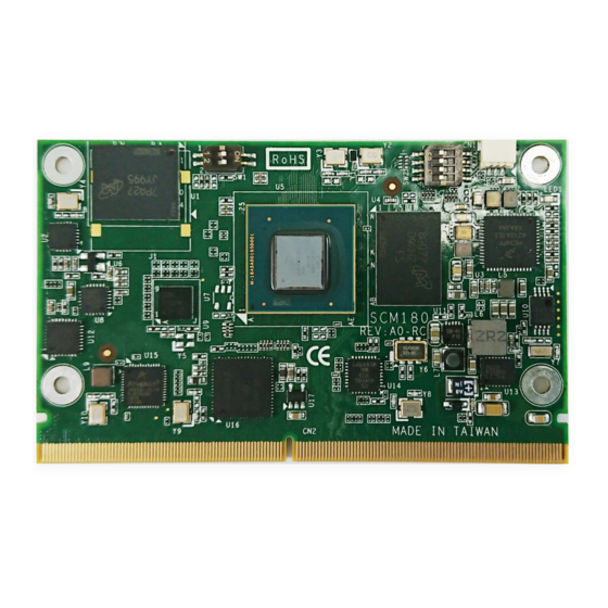
SCM180 & SCB180 Freescale i.MX8M ARM-based System-on-Module Chapter 1 Introduction The SCM180 is a new SMARC v2.0 module to support Freescale i.MX8M series Dual or Quad A53 Core SoCs. It integrates onboard system memory, storage as eMMC, TTL LCD, Audio, USB Host/Client, UARTs, CANBus 2.0B, and various I/O features. -
Page 8: Specifications
SCM180 Freescale i.MX8M ARM-based System-on-Module 1.1 Features Onboard LPDDR4 memory 2GB supports up to 4GB capacity Onboard 8GB eMMC flash as booting device, up to 64GB Two USB 3.0, One USB 2.0 and One USB OTG ... - Page 9 SCM180 & SCB180 Freescale i.MX8M ARM-based System-on-Module PCIe 2 x PCIe 1 x QSPI with 2 chip select; 1 x SPI with 2 chip select GPIO 12 GPIO interfaces (up to 400kbps) via SMARC MXM interface ...
- Page 10 SCM180 Freescale i.MX8M ARM-based System-on-Module This page is intentionally left blank. Introduction...
-
Page 11: Board And Pin Assignments
SCM180 & SCB180 Freescale i.MX8M ARM-based System-on-Module Chapter 2 Board and Pin Assignments 2.1 Board Dimensions and Fixing Holes Top View Bottom View Board and Pin Assignments... -
Page 12: Board Layout
SCM180 Freescale i.MX8M ARM-based System-on-Module 2.2 Board Layout Top View Bottom View Board and Pin Assignments... -
Page 13: Installing Heatsink & Heatspreader
(no space between thermal pad and component) with the corresponding components on the SCM180 module. This is especially critical for SCM180 module that is with high CPU speed to ensure that the heat spreader acts as a proper thermal interface for cooling solutions. -
Page 14: Switch Settings
Similar to Internal Boot mode with one difference: GPIO boot override pins are ignored. Serial Downloader: Provides a means to download a program image to the chip over USB serial connection. 2.4.2 Switch (SW2) SCM180 jumpers are for Carrier Board Function Setting Depend on base board (Default) SW2 (1,2,3,4) OFF... -
Page 15: Chapter 3 Scb120 Baseboard
SCM180 & SCB180 Freescale i.MX8M ARM-based System-on-Module Chapter 3 SCB120 Baseboard The SCB180 is a baseboard for SCM180 SoM. Connect this baseboard properly of SCM180. Its specifications and detailed information are given in this chapter. 3.1 SCB180 Specifications Size ... -
Page 16: Scb180 Dimensions And Fixing Holes
SCM180 Freescale i.MX8M ARM-based System-on-Module 3.2 SCB180 Dimensions and Fixing Holes Top View Bottom View Q7B120 Baseboard... -
Page 17: Scb180 Board Layout
SCM180 & SCB180 Freescale i.MX8M ARM-based System-on-Module 3.3 SCB180 Board Layout Top View Bottom View SCB180 Baseboard... -
Page 18: Jumper Setting
SCM180 Freescale i.MX8M ARM-based System-on-Module 3.4 Jumper setting Jumper is a small component consisting of jumper clip and jumper pins. Install jumper clip on 2 jumper pins to close. And remove jumper clip from 2 jumper pins to open. The following illustration shows how to set up jumper. -
Page 19: Touch Panel Wire Selection (Jp14)
SCM180 & SCB180 Freescale i.MX8M ARM-based System-on-Module 3.4.3 Touch Panel Wire Selection (JP14) Function JP14 Setting 5 – 6 Close 4 Wire 5 – 6 Open 5 Wire Pin Assignment: Signal 4-Wire 5-Wire TS_XN Left LL (L) TS_XP Right LR (X) -
Page 20: Connectors
SCM180 Freescale i.MX8M ARM-based System-on-Module 3.5 Connectors Signals go to other parts of the system through connectors. Loose or improper connection might cause problems, please make sure all connectors are properly and firmly connected. Here is a summary table which shows all connectors on the hardware. -
Page 21: Lvds Connector (Cn1)
SCM180 & SCB180 Freescale i.MX8M ARM-based System-on-Module 3.5.1 LVDS Connector (CN1) This board has a 40-pin connector for LVDS LCD interface. It is strongly recommended to use the matching JST SHDR-40VS-B 40-pin connector for LVDS interface. Pin 1~6 VCCM can be set to +3.3V, +5V or +12V level by setting JP2 (see section 2.3.2). -
Page 22: Com1 Box Header (Cn3)
SCM180 Freescale i.MX8M ARM-based System-on-Module 3.5.3 COM1 Box Header (CN3) This is a 2 x 5 pin 2.0mm pitch box header for interfacing to serial ports. Signal CN3 (for COM1) N.C. N.C. COM1_TX4 COM1_TX3 COM1_RX4 COM1_RX3 N.C. 3.5.4 GPIO I2C SPI Male Connector (CN4) This is a 2x10pin (pitch=1.27mm) connector for GPIO I2C and SPI... -
Page 23: Csi 44Pin Connector (Cn6)
SCM180 & SCB180 Freescale i.MX8M ARM-based System-on-Module 3.5.6 CSI 44pin Connector (CN6) This board also has a 44-pin expansion connector (CN6), It use TE Connectivity AMP Connector 2-1734248-2: Signal Signal CSI_P2_CKN CSI_P2_CKP CSI_P2_DN2 CSI_P2_DP2 CSI_P2_DN3 CSI_P2_DP3 CSI2_nRST_3V3 CSI_MCLK I2C2_SCL_3V3 I2C2_SDA_3V3 3.5.7... -
Page 24: Mxm Connector (Cn8)
SCM180 Freescale i.MX8M ARM-based System-on-Module 3.5.8 MXM Connector (CN8) This SMT type 0.50mm [.020”] pitch, 314-pin MXM connector is available in 2 different heights (5.5mm and 7.8mm) for maximum flexibility. P-Pin Primary (Top) Side S-Pin Secondary (Bottom) Side SMB_ALERT_1V8# CSI1_TX+ / I2C_CAM1_CK... - Page 25 SCM180 & SCB180 Freescale i.MX8M ARM-based System-on-Module Signal Signal SDIO_D2 I2S0_SDIN SDIO_D3 I2S0_CK SPI0_CS0# SPI0_CK SPI0_DIN RSVD SPI0_DO RSVD I2C_GP_CK I2C_GP_DAT ESPI_CS0# ESPI_CS1# ESPI_CK ESPI_IO_2 ESPI_IO_0 ESPI_IO_3 ESPI_IO_1 USB0+ USB0- USB0_EN_OC# USB3_SSTX+ USB0_VBUS_DET USB3_SSTX- USB0_OTG_ID USB1+ USB3_SSRX+ USB1- USB3_SSRX- USB1_EN_OC#...
- Page 26 SCM180 Freescale i.MX8M ARM-based System-on-Module Signal Signal PCIE_A_TX- PCIE_B_TX+ PCIE_B_TX- HDMI_D2+ / DP1_LANE0+ HDMI_D2- / DP1_LANE0- DP0_LANE0+ DP0_LANE0- HDMI_D1+ / DP1_LANE1+ DP0_AUX_SEL HDMI_D1- / DP1_LANE1- DP0_LANE1+ DP0_LANE1- HDMI_D0+ / DP1_LANE2+ DP0_HPD HDMI_D0- / DP1_LANE2- DP0_LANE2+ P100 S100 DP0_LANE2- P101 HDMI_CK+ / DP1_LANE3+...
- Page 27 SCM180 & SCB180 Freescale i.MX8M ARM-based System-on-Module Signal Signal P137 SER2_RX S137 LVDS0_3+ / eDP0_TX3+ / DSI0_D3+ P138 SER2_RTS# S138 LVDS0_3- / eDP0_TX3- / DSI0_D3- P139 SER2_CTS# S139 I2C_LCD_CK P140 SER3_TX S140 I2C_LCD_DAT P141 SER3_RX S141 LCD0_BKLT_PWM P142 S142 RSVD...
-
Page 28: Usb 2.0 Wafer Connector (Cn9)
SCM180 Freescale i.MX8M ARM-based System-on-Module 3.5.9 USB 2.0 Wafer Connector (CN9) This is a 5x2-pin (pitch=2.00mm) connector for USB 2.0 interface. Signal Signal USB_DM_DN1_CN USB_DP_DN1_CN 3.5.10 HDMI Connector (CN11) The HDMI (High-Definition Multimedia Interface) is a compact digital interface which is capable of transmitting high-definition video and high-resolution audio over a single cable. -
Page 29: Com3 Connector (Cn12A)
SCM180 & SCB180 Freescale i.MX8M ARM-based System-on-Module 3.5.12 COM3 Connector (CN12A) These is standard 9-pin D-Sub connectors for interfacing to serial ports. Signal CN12A (COM3) N.C. DTE_RXD2 DTE_RTS2 N.C. N.C. DTE_TXD2 DTE_CTS2 N.C. 3.5.13 USB 3.0 Double Deck Port (CN13) The motherboard comes with one stacked Universal Serial Bus (compliant with USB 3.0) -
Page 30: Mini Usb Otg Port Host/Device Connector (Cn15)
SCM180 Freescale i.MX8M ARM-based System-on-Module 3.5.15 Mini USB OTG Port Host/Device Connector (CN15) USB On-The-Go, often abbreviated USB OTG, is a specification that allows USB devices such as digital audio players or mobile phones to act as a host, allowing other USB devices like a USB flash drive, mouse, or keyboard to be attached to them. -
Page 31: Full Size Mini Card Socket (Scn2)
SCM180 & SCB180 Freescale i.MX8M ARM-based System-on-Module 3.5.19 Full Size Mini Card Socket (SCN2) Signal Signal +3.3VAUX WAKE# +1.5V UIM_PWR UIM_DAT REFCLK- UIM_CLK REFCLK+ UIM_REST UIM_VPP UIM_C8 UIM_C4 PERST# +3.3VAUX PERN0 PERP0 +1.5V SMB_CLK SMB_DATA PETN0 PETP0 USB_D- USB_D+ +3.3VAUX +3.3VAUX... -
Page 32: Half Size Mini Card Socket (Scn3)
SCM180 Freescale i.MX8M ARM-based System-on-Module 3.5.20 Half Size Mini Card Socket (SCN3) Signal Signal +3.3VAUX WAKE# +1.5V REFCLK- REFCLK+ PERST# +3.3VAUX PERN0 PERP0 +1.5V SMB_CLK SMB_DATA PETN0 PETP0 USB_D- USB_D+ +3.3VAUX +3.3VAUX +1.5V +3.3VAUX 3.5.21 SIM Card Slot (SCN4) The SCN4 is for inserting SIM Card and mainly used in 3G/4G/LTE wireless network application. -
Page 33: Power On/Off Switch (Sw3)
SCM180 & SCB180 Freescale i.MX8M ARM-based System-on-Module 3.5.22 Power On/Off Switch (SW3) The SW3 is the Power On/Off switch, when push the button and system is on, the LED light will show Blue Color. 3.5.23 Reset Button (SW4) The SW4 is the reset button that reboot your system.