
Related Manuals for AXIOMTEK SHB101 Series


Summary of Contents for AXIOMTEK SHB101 Series
- Page 1 SHB101 Series ™ ™ ® Intel Core 2 Quad/Core 2 Duo ® Celeron Processor PICMG 1.3 Full- Size Single Board Computer User’s Manual...
- Page 2 AXIOMTEK does not warrant or assume any legal liability or responsibility for the accuracy, completeness or usefulness of any information in this document. AXIOMTEK does not make any commitment to update the information in this manual.
-
Page 3: Esd Precautions
Wear a wrist-grounding strap, available from most electronic component stores, when handling boards and components. Trademarks Acknowledgments AXIOMTEK is a trademark of AXIOMTEK Co., Ltd. ® Windows is a trademark of Microsoft Corporation. Phoenix & AWARD are trademarks of Phoenix Technology Ltd. -
Page 4: Table Of Contents
Table of Contents Disclaimers ....................... ii ESD Precautions ..................... iii CHAPTER 1 INTRODUCTION..................1 Specifications....................2 Utilities Supported..................3 I/O Bracket ....................4 CHAPTER 2 JUMPERS AND CONNECTORS ............... 5 Board Dimensions..................5 Board Layout ....................6 Jumper Settings ..................7 2.3.1 COM2 Mode Select Jumpers for RS-232/422/485 (JP1, JP2, JP3).. - Page 5 Getting Help ....................30 The Main Menu ..................31 Standard CMOS Setup Menu ..............32 Advanced BIOS Features ................. 35 Advanced Chipset Features ..............40 Integrated Peripherals ................42 Power Management Setup ................ 46 5.10 PnP/PCI Configuration Setup ..............50 5.11 PC Health Status ..................
- Page 6 MEMO...
-
Page 7: Chapter 1 Introduction
SHB101 LGA775 Full-Size SBC User’s Manual CHAPTER 1 INTRODUCTION The SHB101 PICMG 1.3 full-size Single Board Computer supports ® ® ™ ™ LGA775 socket for Intel Core 2 Quad / Core 2 Duo/Celeron processors with 45/65nm technology and FSB 800/1066/1333 MHz. ®... -
Page 8: Specifications
SHB101 LGA775 Full-Size SBC User’s Manual Specifications ® ® ™ ™ Intel Core 2 Quad / Core 2 Duo/Celeron processors System Chipset ® Intel Q35 and ICH9R CPU Socket LGA775 Socket Front-Side Bus 800/1066/1333 MHz ... -
Page 9: Utilities Supported
SHB101 LGA775 Full-Size SBC User’s Manual preallocated memory for frame buffer option as 8MB Resolution -- Analog output -- the analog port utilizes an integrated 350MHz 24-bit RAMDAC that can directly drive a standard progressive scan analog monitor up to a resolution of 2048x1536 pixels with 32-bit color at 75 Hz Analog Output Interface -- CRT from DAC output via 15-pin ... -
Page 10: I/O Bracket
SHB101 LGA775 Full-Size SBC User’s Manual I/O Bracket Introduction... -
Page 11: Chapter 2 Jumpers And Connectors
SHB101 LGA775 Full-Size SBC User’s Manual CHAPTER 2 JUMPERS AND CONNECTORS Board Dimensions Jumpers and Connectors... -
Page 12: Board Layout
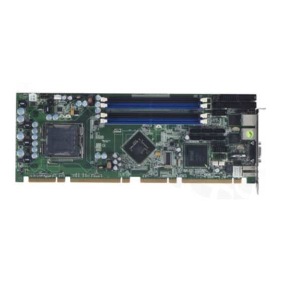
SHB101 LGA775 Full-Size SBC User’s Manual Board Layout Jumpers and Connectors... -
Page 13: Jumper Settings
SHB101 LGA775 Full-Size SBC User’s Manual Jumper Settings Proper jumer settings configure the SHB101 to meet your application purpose. 2.3.1 COM2 Mode Select Jumpers for RS-232/422/485 (JP1, JP2, JP3) These jumpers select the COM2 port’s communication mode to operate RS-232 or RS-422/485. Description Function Jumper Setting COM2... -
Page 14: Cmos Clear Jumper (Jp6)
SHB101 LGA775 Full-Size SBC User’s Manual 2.3.2 CMOS Clear Jumper (JP6) You may need to use this jumper is to clear the CMOS memory if incorrect BIOS settings. Description Function Jumper Setting Normal CMOS (Default) Clear Clear CMOS 2.3.3 ATX Auto Power On/Off (JP7) When Jumper JP7 is set OPEN for AC power input, the system will be automatically power ON without pressing soft power button;... -
Page 15: Connectors
SHB101 LGA775 Full-Size SBC User’s Manual Connectors Connectors connect this board with other parts of the system. Loose or improper connection might cause problems. Make sure all connectors are properly and firmly connected. Here is a summary table shows you all connectors on the board. Connector Label Connector... -
Page 16: Atx 4 Pin 12V In Connector (Cn2)
SHB101 LGA775 Full-Size SBC User’s Manual 2.4.1 ATX 4 Pin 12V In Connector (CN2) You can connect it to the ATX12V power supply for CPU Core Voltage. Signal +12V +12V 2.4.2 Front Panel Connector (CN3) Power LED This 3-pin connector denoted as Pin 1 and Pin 5 connects the system power LED indicator to such a switch on the case. -
Page 17: Lan1, Lan2 Link/Active Led Connectors (Cn4, Cn7)
SHB101 LGA775 Full-Size SBC User’s Manual control ATX power supply to be power on/off. System Reset Switch Pin 11 and 12 can be connected to the case-mounted reset switch that reboots your computer instead of turning OFF the power switch. It is a better way to reboot your system for a longer life of the system’s power supply. -
Page 18: Com Port Rs-232 Pin Assignment (Com1, Com2)
SHB101 LGA775 Full-Size SBC User’s Manual 2.4.5 COM Port RS-232 Pin Assignment (COM1, COM2) The serial interface for the board consists of COM1 port (COM1) support for RS-232, and COM2 (COM2) for RS-232/RS422/RS485. Signal Signal COM1, COM2 Data Carrier Detect Data Set Ready (DSR) (DCD) Receive Data (RXD) -
Page 19: Cpu Fan Connector (Fan1)
SHB101 LGA775 Full-Size SBC User’s Manual 2.4.7 CPU Fan Connector (FAN1) A CPU fan is always needed for cooling CPU heat. The CPU fan connector FAN1 provides power to the CPU fan. Signal FAN1 1 Ground 2 +12V 3 Rotation Detection 4 Speed Control 2.4.8 System Fan Connectors (FAN2, FAN3) -
Page 20: Hd Audio Digital Header (Hda1)
SHB101 LGA775 Full-Size SBC User’s Manual Signal Signal Signal 28 Write protect# 29 No connector 30 Read data# 31 GND 32 Head selection# 33 No connector 34 Disk change# FDD1 ® 2.4.10 Intel HD Audio Digital Header (HDA1) Signal Signal HDA1 BCLK RST#... -
Page 21: Ps/2 Keyboard, Mouse Connector (Kb1, Ms1)
SHB101 LGA775 Full-Size SBC User’s Manual 2.4.11 PS/2 Keyboard, Mouse Connector (KB1, MS1) The board provides the Keyboard (KB1)/ Mouse (MS1) interface with a 5-pin connector. Signal Clock KB1/MS1 DATA No connector 2.4.12 Ethernet RJ-45 Connectors (LAN1/LAN2) The RJ-45 connectors LAN1 and LAN2 are for Ethernet. To connect the board to 100-Base-T or 1000-Base-T hub, just plug one end of the cable into LAN1 and connect the other end (phone jack) to a 100- Base-T hub or 1000-Base-T hub. -
Page 22: Parallel Port Connector (Prn1)
SHB101 LGA775 Full-Size SBC User’s Manual 2.4.13 Parallel Port Connector (PRN1) Print Port Connector [Default] This board has a multi-mode parallel port to support: 1. Standard Mode: IBM PC/XT, PC/AT and PS/2 are compatible with bi-directional parallel port. 2. Enhanced Mode: Enhance parallel port (EPP) is compatible with EPP 1.7 and EPP 1.9 (IEEE 1284 compliant). -
Page 23: Sata Connectors (Sata1~6)
SHB101 LGA775 Full-Size SBC User’s Manual 2.4.14 SATA Connectors (SATA1~6) These SATA connectors are for high-speed SATA interface ports and they can be connected to hard disk devices. SATA1~6 Signal SATA_TX+ SATA_TX- SATA_RX- SATA_RX+ 2.4.15 USB Connectors (USB1/USB2) The 10-pin standard Universal Serial Bus (USB) connectors, USB1/2, on this board are for installing versatile USB interface peripherals. -
Page 24: Usb Port Connector (Usb3/Usb4)
SHB101 LGA775 Full-Size SBC User’s Manual 2.4.16 USB Port Connector (USB3/USB4) The 4-pin standard Universal Serial Bus (USB) port connector on the board is for the installation of peripherals supporting the USB interface. USB3/4 Signal USB POWER USB - USB + 2.4.17 DB15 CRT Connector (VGA1) VGA1 is a DB15 connector commonly used for the CRT Monitor. -
Page 25: Chapter 3 Hardware Installation
SHB101 LGA775 Full-Size SBC User’s Manual CHAPTER 3 HAREDWARE INSTALLATION ® Before installing the processor, please access Intel website for more detailed information http://www.intel.com . Installing the Processor The LGA775 processor socket comes with a cover to protect the processor. Please install the processor into the CPU socket step by step as below: Hold the hook (A) of the lever and push it down. - Page 26 SHB101 LGA775 Full-Size SBC User’s Manual Open the cover (C), you Be careful not to touch the can see the contact. contact (D). Remove the plastic cap (E) from the cover. Hardware Installation...
- Page 27 SHB101 LGA775 Full-Size SBC User’s Manual Place the CPU down into the socket. Be careful not to touch the contact. Hold the edges of the CPU, and orientate it as the marked direction (G) down into the socket to match the (H) and (F) locations. Hardware Installation...
- Page 28 SHB101 LGA775 Full-Size SBC User’s Manual Slightly push down the cover and hook the lever (I~J). The CPU is completely locked. Orientate the CPU cooling fan to fixing holes on the board. Hardware Installation...
- Page 29 SHB101 LGA775 Full-Size SBC User’s Manual Screw the CPU cooling fan onto the board. Make sure the CPU fan is plugged to the CPU fan connector. Hardware Installation...
-
Page 30: Installing The Memory
SHB101 LGA775 Full-Size SBC User’s Manual Installing the Memory The board supports four 240-pin DDR2 DIMM memory sockets with maximum memory capacity up to 8GB. Please follow steps below to install the memory modules: Push down latches on each side of the DIMM socket. Align the memory module with the socket that notches of memory module must match the socket keys for a correct intallation. -
Page 31: Chapter 4 Hardware Description
CPU from damages. BIOS The SHB101 Series uses Phoenix-Award Plug and Play BIOS with a single 8Mbit SPI Flash. System Memory The SHB101 Series supports four 240-pin DDR2 DIMM sockets for a maximum memory of 8GB DDR2 SDRAMs. -
Page 32: I/O Port Address Map
SHB101 LGA775 Full-Size SBC User’s Manual I/O Port Address Map ® ® ™ ™ The Intel Core 2 Quad / Core 2 Duo/Celeron CPUs can communicate via I/O ports. There are total 1KB port addresses available for assignment to other devices via I/O expansion cards. Address Devices 000-01F... -
Page 33: Interrupt Controller (Irq) Map
Serial port #2 (COM2) Interrupt Controller (IRQ) Map The SHB101 Series is a 100% PC compatible control board. It consists of 16 interrupt request lines, and four out of them can be programmable. The mapping list of the 16 interrupt request lines is shown as the following table. - Page 34 SHB101 LGA775 Full-Size SBC User’s Manual MEMO Hardware Description...
-
Page 35: Chapter 5 Phoenix-Award Bios Utility
SHB101 LGA775 Full-Size SBC User’s Manual CHAPTER 5 PHOENIX-AWARD BIOS UTILITY The Phoenix-Award BIOS provides users with a built-in Setup program to modify basic system configuration. All configured parameters are stored in a battery-backed-up RAM (CMOS RAM) to save the Setup information whenever the power is turned off. -
Page 36: Control Keys
SHB101 LGA775 Full-Size SBC User’s Manual Control Keys Move cursor to the previous item Up arrow Move cursor to the next item Down arrow Move cursor to the item on the left hand Left arrow Move to the item in the right hand Right arrow Main Menu -- Quit and delete changes into CMOS Status Page Setup Menu and Option Page Setup... -
Page 37: The Main Menu
SHB101 LGA775 Full-Size SBC User’s Manual The Main Menu Once you enter the Phoenix-Award BIOS CMOS Setup Utility, the Main Menu appears on the screen. In the Main Menu, there are several Setup functions and a couple of Exit options for your selection. Use arrow keys to select the Setup Page you intend to configure then press <Enter>... -
Page 38: Standard Cmos Setup Menu
SHB101 LGA775 Full-Size SBC User’s Manual Standard CMOS Setup Menu The Standard CMOS Setup Menu displays basic information about your system. Use arrow keys to highlight each item, and use <PgUp> or <PgDn> key to select the value you want in each item. Date ... - Page 39 SHB101 LGA775 Full-Size SBC User’s Manual 24-hour military-time clock. For example, 1 p.m. is 13:00:00. IDE Channel 0/1/2/3 Master/IDE Channel 0/1 Slave These items identify the types of each IDE channel installed in the computer. There are 45 predefined types (Type 1 to Type 45) and 2 user’s definable types (Type User) for Enhanced IDE BIOS.
- Page 40 SHB101 LGA775 Full-Size SBC User’s Manual Halt On This item determines whether the system will halt or not, if an error is detected while powering up. The system booting will halt on any errors detected. No errors (default) Whenever BIOS detects a non-fatal error, the All errors system will stop and you will be prompted.
-
Page 41: Advanced Bios Features
SHB101 LGA775 Full-Size SBC User’s Manual Advanced BIOS Features This section allows you to configure and improve your system, to set up some system features according to your preference. Phoenix-Award BIOS Utility... - Page 42 SHB101 LGA775 Full-Size SBC User’s Manual CPU Feature Scroll to this item and press <Enter> to view the CPU Feature sub menu. Limit CPUID MaxVal The CPUID instruction if some newer CPUs will return a value greater than 3. The default is “Disabled“, because this problem does not exist in the Windows series operating systems.
- Page 43 SHB101 LGA775 Full-Size SBC User’s Manual Hard Disk Boot Priority Scroll to this item and press <Enter> to view the sub menu to decide the disk boot priority. Press <Esc> to return to the Advanced BIOS Features page. Phoenix-Award BIOS Utility...
- Page 44 SHB101 LGA775 Full-Size SBC User’s Manual CD-ROM Boot Priority Scroll to this item and press <Enter> to view the sub menu to decide the CD-ROM boot priority. Press <Esc> to return to the Advanced BIOS Features page. Quick Power On Self Test ...
- Page 45 SHB101 LGA775 Full-Size SBC User’s Manual Boot Up NumLock Status Set the the Num Lock status when the system is powered on. The default value is “On”. Security Option This item allows you to limit access to the system and Setup, or just to Setup.
-
Page 46: Advanced Chipset Features
SHB101 LGA775 Full-Size SBC User’s Manual Advanced Chipset Features This section contains completely optimized chipset’s features on the board that you are strongly recommended to leave all items on this page at their default values unless you are very familiar with the technical specifications of your system hardware. - Page 47 SHB101 LGA775 Full-Size SBC User’s Manual Press <Esc> to return to the Advanced Chipset Features page. VT-d Use this item to enable or disable the VT-d to support the remapping of I/O DMA transfers and device-generated interrupts. ** VGA Setting ** PEG/Onchip VGA Control ...
-
Page 48: Integrated Peripherals
SHB101 LGA775 Full-Size SBC User’s Manual Integrated Peripherals This section allows you to configure your SuperIO Device, IDE Function and Onboard Device. OnChip IDE Device Scroll to this item and press <Enter> to view the sub menu OnChip IDE Device. Phoenix-Award BIOS Utility... - Page 49 SHB101 LGA775 Full-Size SBC User’s Manual IDE HDD Block Mode Block mode is also called block transfer, multiple commands, or multiple sector read/write. If your IDE hard drive supports block mode (most new drives do), select Enabled for automatic detection of the optimal number of block read/writes per sector the drive can support.
- Page 50 SHB101 LGA775 Full-Size SBC User’s Manual Super IO Device Scroll to this item and press <Enter> to view the sub menu Super IO Device. Onboard FDC Controller Select Enabled, if your system has a floppy disk controller (FDC) installed on the system board and you want to use it. If you install and-in FDC or the system has no floppy drive, select Disabled in this field.
- Page 51 SHB101 LGA775 Full-Size SBC User’s Manual Select a DMA channel for the parallel port while using the ECP mode. PWRON After PWR-Fail This item enables your computer to automatically restart or return to its operating status. Press <Esc> to return to the Integrated Peripherals page. USB Device Setting ...
-
Page 52: Power Management Setup
SHB101 LGA775 Full-Size SBC User’s Manual Power Management Setup The Power Management Setup allows you to save energy of your system effectively. It will shut down the hard disk and turn OFF video display after a period of inactivity. ACPI Function ... - Page 53 SHB101 LGA775 Full-Size SBC User’s Manual powered while most other hardware components turn off to save energy. The information stored in memory will be used to restore the system when a “wake up” event occurs. Run VGABIOS if S3 Resume ...
- Page 54 SHB101 LGA775 Full-Size SBC User’s Manual After the selected period of system inactivity (1 minute to 1 hour), all devices except the CPU shut off. The default value is “Disabled”. Disabled System will never enter SUSPEND mode 1/2/4/6/8/10/ Defines the continuous idle time before the system 20/30/40 entering SUSPEND mode.
- Page 55 SHB101 LGA775 Full-Size SBC User’s Manual access times, and support for aperiodic behavior. Phoenix-Award BIOS Utility...
-
Page 56: Pnp/Pci Configuration Setup
SHB101 LGA775 Full-Size SBC User’s Manual HPET Mode Use this item to configure the HPET (High Precision Event Timer) mode. Press <Esc> to return to the Main Menu page. 5.10 PnP/PCI Configuration Setup This section describes the configuration of PCI (Personal Computer Interconnect) bus system, which allows I/O devices to operate at speeds close to the CPU speed while communicating with other important components. - Page 57 SHB101 LGA775 Full-Size SBC User’s Manual Reset Configuration Data Normally, you leave this item Disabled. Select Enabled to reset Extended System Configuration Data (ESCD) when you exit Setup or if installing a new add-on cause the system reconfiguration a serious conflict that the operating system can not boot.
-
Page 58: Pc Health Status
SHB101 LGA775 Full-Size SBC User’s Manual ** PCI Express relative items ** Maximum Payload Size When using DDR SDRAM and Buffer size selection, another consideration in designing a payload memory is the size of the buffer for data storage. Maximum Payload Size defines the maximum TLP (Transaction Layer Packet) data payload size for the device. -
Page 59: Frequency/Voltage Control
SHB101 LGA775 Full-Size SBC User’s Manual CPU FAN Speed These optional and read-only items show current speeds in RPM (Revolution Per Minute) for the CPU fan and chassis fan as monitored by the hardware monitoring IC. SYSTEM FAN1 Speed ... -
Page 60: Load Fail-Safe Defaults
SHB101 LGA775 Full-Size SBC User’s Manual Interference). Spread Spectrum If spread spectrum is enabled, EMI (ElectroMagnetic Interference) generated by the system can be significantly reduced. Press <Esc> to return to the Main Menu page. 5.13 Load Fail-Safe Defaults When you press <Enter> on this item, a confirmation dialog box pops out to show you such a message: Please press “Y”... -
Page 61: Load Optimized Defaults
SHB101 LGA775 Full-Size SBC User’s Manual 5.14 Load Optimized Defaults This option allows you to load your system configuration with default values. These default settings are optimized to enable high performance features. To load CMOS SRAM with SETUP default values, please enter “Y”. If not, please enter “N”. -
Page 62: Set Supervisor/User Password
SHB101 LGA775 Full-Size SBC User’s Manual 5.15 Set Supervisor/User Password You can set a supervisor or user password, or both of them. The differences between them are: Supervisor password: You can enter and change the options on the setup menu. User password: You can just enter, but have no right to change the options on the setup menu. -
Page 63: Save & Exit Setup
SHB101 LGA775 Full-Size SBC User’s Manual 5.16 Save & Exit Setup This section allows you to determine whether or not to accept your modifications. Type “Y” to quit the setup utility and save all changes into the CMOS memory. Type “N” to bring you back to the Setup utility. Phoenix-Award BIOS Utility... -
Page 64: Exit Without Saving
SHB101 LGA775 Full-Size SBC User’s Manual 5.17 Exit Without Saving Select this option to exit the Setup utility without saving changes you have made in this session. Type “Y”, and it will quit the Setup utility without saving your modifications. Type “N” to return to the Setup utility. - Page 65 SHB101 LGA775 Full-Size SBC User’s Manual MEMO Phoenix-Award BIOS Utility...
-
Page 66: Chpater 6 Installation Of Drivers
INSTALLATION OF DRIVERS The device drivers are located on the Product Information CD-ROM that comes with the SHB101 Series package. The auto-run function of drivers will guide you to install the utilities and device drivers under a Windows system. You can follow the onscreen instructions to install... - Page 67 SHB101 LGA775 Full-Size SBC User’s Manual ® An Intel License Agreement appears to show you the important information. Click “Yes” to next step. Please wait while running the following setup operations. (3-1) Installation of Drivers...
- Page 68 SHB101 LGA775 Full-Size SBC User’s Manual (3-2) Click “Finish” to complete the setup process. Instalation of Drivers...
-
Page 69: Installing Vga Driver
SHB101 LGA775 Full-Size SBC User’s Manual You will be asked to reboot your computer when the installation is completed. Please click “Yes, I want to restart my computer now” if you don’t need to install any other drivers. Otherwise, please click “No, I will restart my computer later”, and go on next step. - Page 70 SHB101 LGA775 Full-Size SBC User’s Manual ® An Intel License Agreement appears to show you the important information. Click “Yes” to next step. The message of Readme File Information appears to show you the system requirements and installation information. Please click “Next”. Instalation of Drivers...
- Page 71 SHB101 LGA775 Full-Size SBC User’s Manual Please wait while running the following setup operations. When this message appears, please click “Next”. Click “Finish” to complete the setup process. Installation of Drivers...
-
Page 72: Installing Lan Driver
SHB101 LGA775 Full-Size SBC User’s Manual You will be asked to reboot your computer when the installation is completed. Please click “Yes, I want to restart my computer now” if you don’t need to install any other drivers. Otherwise, please click “No, I will restart my computer later”, and click “Finish”... - Page 73 SHB101 LGA775 Full-Size SBC User’s Manual Click “Install” to start the installation. 3. Please wait while running the following installation operation. Installation of Drivers...
- Page 74 SHB101 LGA775 Full-Size SBC User’s Manual Click “Finish” to complete the installation. Note The Driver item [Wake on Directed Packet] default is Enabled under Windows Vista. Instalation of Drivers...
- Page 75 SHB101 LGA775 Full-Size SBC User’s Manual MEMO Installation of Drivers...
-
Page 76: Appendix A Watchdog Timer
SHB101 LGA775 Full-Size SBC User’s Manual APPENDIX A WATCHDOG TIMER Watchdog Timer Setting After the system stops working for a while, it can be auto-reset by the Watchdog Timer. The integrated Watchdog Timer can be set up in the system reset mode by program. Using the Watchdog Function Start ... - Page 77 SHB101 LGA775 Full-Size SBC User’s Manual IF No re-set timer :WDT time-out, generate RESET IF to disable WDT :O 2E 30 O 2F 00 ; Can be disable at any time N=00 M= 00h: Time-out Disable 01h: Time-out occurs after 1 second 02h: Time-out occurs after 2 second 03h: Time-out occurs after 3 second ………………………........
-
Page 78: Appendix B Pci Irq Routing
SHB101 LGA775 Full-Size SBC User’s Manual APPENDIX B PCI IRQ ROUTING PICMG PCI IRQ Routing Device Slot PCI Slot 0 BCDA PCI Slot 1 CDAB PCI Slot 2 DABC PCI Slot 3 ABCD PCI IRQ Routing... - Page 79 SHB101 LGA775 Full-Size SBC User’s Manual MEMO PCI IRQ Routing...
-
Page 80: Appendix C Configuring Sata For Raid Function
SHB101 LGA775 Full-Size SBC User’s Manual APPENDIX C CONFIGURING SATA FOR RAID FUNCTION Configuring SATA Hard Drive(s) for RAID ® Function (Controller: Intel ICH9R/DO DH only) Please follow up the steps below to configure SATA hard drive(s): (1) Install SATA hard drive(s) in your system. (2) Enter the BIOS Setup to configure SATA controller mode and boot sequence. - Page 81 SHB101 LGA775 Full-Size SBC User’s Manual (2)-1 Turn on your system and press the Del button to enter BIOS Setup during running POST (Power-On Self Test). Figure 1 Configuring SATA for RAID Function...
- Page 82 SHB101 LGA775 Full-Size SBC User’s Manual (2)-2 Set CDROM for First Boot Device under the Advanced BIOS Features menu to boot CD-ROM after system restarts (Figure 2). Figure 2 (2)-3 Save and exit the BIOS Setup. (3) Configuring RAID by the RAID BIOS Enter the RAID BIOS setup utility to configure a RAID array.
- Page 83 SHB101 LGA775 Full-Size SBC User’s Manual (3)-1 After the POST memory testing and before the operating system booting, a message "Press <Ctrl-I> to enter Configuration Utility" (as Figure 3) shows up, accordingly, press <CTRL+ I> to enter the RAID BIOS setup utility. Figure 3 (3)-2 After you press <CTRL+ I>, the Create RAID Volume screen...
- Page 84 SHB101 LGA775 Full-Size SBC User’s Manual (3)-3 After entering the CREAT VOLUME MENU screen, you can type the disk array name with 1~16 letters (letters cannot be special characters) in the item “Name”. When finished, press ENTER to select a RAID level (as Figure 5). There are three RAID levels, RAID0, RAID1 and RAID5&RAID10.
- Page 85 SHB101 LGA775 Full-Size SBC User’s Manual (3)-5 After setting all the items on the menu, select Create Volume and press ENTER (as Figure 7) to start creating the RAID array. Figure 7 (3)-6 When prompting the confirmation, press “Y“ to create this volume, or “N“...
- Page 86 SHB101 LGA775 Full-Size SBC User’s Manual After the creation is completed, you can see detailed information about the RAID Array in the DISK/VOLUME INFORMATION section, including RAID mode, disk block size, disk name, and disk capacity, etc. Figure 9 Configuring SATA for RAID Function...
- Page 87 SHB101 LGA775 Full-Size SBC User’s Manual Delete RAID Volume If you want to delete a RAID volume, select the Delete RAID Volume option in Main Menu. Press ENTER and follow on-screen instructions. Figure 10 Please press [ESC] to exit theICH9R RAID BIOS utility. Now, you can proceed to install a SATA driver controller and the operating system.
- Page 88 SHB101 LGA775 Full-Size SBC User’s Manual (4)-1 Users can insert the Driver CD and the formatted blank floppy disk in another system. And then, please execute the f6flpy32.exe file in the folder of the Driver CD. Note Please execute the f6flpy64.exe file, if installing 64- bit Windows Operating System.
- Page 89 SHB101 LGA775 Full-Size SBC User’s Manual (4)-3 When the RAID Driver is written to the floppy disk, the SATA driver disk is completed. Note Please execute the f6flpy64.exe file, if installing 64-bit Windows Operating System. (5) Installing the SATA controller driver during the OS installation Now, the SATA driver disk is ready, and BIOS settings configured, you can proceed to install Windows 2000/XP onto your SATA hard drive using the SATA driver.
- Page 90 SHB101 LGA775 Full-Size SBC User’s Manual (5)-1 Restart your system to boot the Windows 2000/XP Setup disk, and press F6 butoon button as soon as you see the message "Press F6 if you need to install a 3rd party SCSI or RAID driver"...
- Page 91 SHB101 LGA775 Full-Size SBC User’s Manual (5)-3 If the Setup correctly recognizes the driver of the floppy disk, a controller menu (as Figure 13) will appear below. Use the ARROW keys to select Intel(R) 82801IR/ IHO SATA RAID Controller and press ENTER. Then it will begin to load the SATA driver from the floppy disk.
-
Page 92: Appendix D Picmg V1.3 Interface Definition
SHB101 LGA775 Full-Size SBC User’s Manual APPENDIX D PICMG v1.3 INTERFACE DEFINITION x16 PCIe Connector A x16 PCIe Connector C Side B Side A Side B Side A 1 N.C 1 USB0P 2 GND 2 USB0N 3 N.C 3 GND USB1P 4 N.C 4 GND... - Page 93 SHB101 LGA775 Full-Size SBC User’s Manual 31 GND REFCLK1+ 31 N.C 32 RSVD REFCLK1- 32 N.C 33 REFCLK2+ 33 N.C 34 REFCLK2- 34 N.C 35 GND REFCLK3+ 35 N.C 36 RSVD REFCLK3- 36 GND 37 REFCLK4+ 37 GND 38 REFCLK4- 38 N.C 39 GND 39 N.C...
- Page 94 SHB101 LGA775 Full-Size SBC User’s Manual 69 a_PETp6 69 GND 70 a_PETn6 70 GND 71 GND a_PERp6 71 GND 72 GND a_PERn6 72 GND 73 a_PETp7 73 +12V +12V 74 a_PETn7 74 +12V +12V 75 GND a_PERp7 75 +12V +12V 76 GND a_PERn7 76 +12V...
- Page 95 SHB101 LGA775 Full-Size SBC User’s Manual 22 a_PETn12 22 C/BE3# AD24 23 GND a_PERp12 23 AD23 +3.3V 24 GND a_PERn12 24 GND AD22 25 a_PETp13 25 AD21 AD20 26 a_PETn13 26 AD19 27 GND a_PERp13 27 +5V AD18 28 GND a_PERn13 28 AD17 AD16...