
Related Manuals for AXIOMTEK SHB100


Summary of Contents for AXIOMTEK SHB100
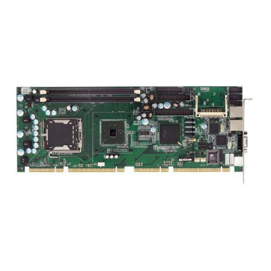
- Page 1 SHB100 ® Intel Core2 ® Duo/PentiumD/Pentium4/CeleronD PICMG 1.3 Full-Size Single Board Computer User’s Manual...
- Page 2 Axiomtek does not make any commitment to update the information in this manual. Axiomtek reserves the right to change or revise this document and/or product at any time without notice. No part of this document may be reproduced, stored in a retrieval system, or transmitted, in any form or by any means, electronic, mechanical, photocopying, recording, or otherwise, without the prior written permission of Axiomtek Co., Ltd.
-
Page 3: Esd Precautions
Wear a wrist-grounding strap, available from most electronic component stores, when handling boards and components. Trademarks Acknowledgments Axiomtek is a trademark of Axiomtek Co., Ltd. ® Windows is a trademark of Microsoft Corporation. AMI is a trademark of American Megatrend Inc. - Page 4 2.3.8 IrDA connector (JP13) ................. 9 2.3.9 CMOS Clear Jumper (JP14) ..............10 2.3.10 Processor List for Intel Core2 Duo CPU(For B1 PCB version of SHB100 only) ......................10 Connectors ..................11 2.4.1 Front Panel Connector (CN19) ..............12 2.4.2 Enhanced IDE Interface connector (CN10) ..........
- Page 5 Installing the Memory ............... 24 Installing the Backplane ..............24 3.4.1 Notice for SHB100..................24 3.4.2 How to install the PICMG1.3 backplane for SHB100 ........ 25 Chapter 4 Hardware Description ......27 Microprocessors ................27 BIOS ....................27 System Memory ................. 27 I/O Port Address Map ................
- Page 6 6.2.3 Drivers Supported ..................56 Appendix A Watchdog Timer ........57 Appendix B PCI IRQ Routing ........59 Appendix C Memory Mapping ........61...
-
Page 7: Chapter 1 Introduction
Intel 82945G ® Intel 82801GR(ICH7R) CPU Socket LGA775 Front-Side Bus 533MHz/800/1066MHz For 1066 MHz FSB speed of Intel processor. The SHB100 only support Pentium4 Extreme Editition. Note BIOS Phoenix-Award PnP Flash BIOS. Introduction... - Page 8 SHB100 LGA775 SBC User’s Manual System Memory Support DD2-400/533/667 memory and up to 4GB Due to standard PC architecture, a certain amount of memory is reserved for system usage and therefore the actual memory size is less than the stated amount.
-
Page 9: Utilities Supported
SHB100 LGA775 SBC User’s Manual Utilities Supported ® Intel 945G Utility and Drivers VGA Drivers Ethernet Utility and Drivers Audio Utility and Drivers Ordering information Model number Description SHB100V2G PCI-E LAN Chipx2 (Intel573E/V/L) SHB100VG PCI-E LAN Chipx1 (Intel573E/V/L) - Page 10 SHB100 LGA775 SBC User’s Manual This page is intentionally left blank. Introduction...
-
Page 11: Chapter 2 Board And Pin Assignments
SHB100 LGA775 SBC User’s Manual Chapter 2 Board and Pin Assignments Board Dimensions Board and Pin Assignments... -
Page 12: Board Layout
SHB100 LGA775 SBC User’s Manual Board Layout Board and Pin Assignments... -
Page 13: Jumper Settings
SHB100 LGA775 SBC User’s Manual Jumper Settings Proper jumper settings configure the SHB100 to meet your application purpose. Description Function Jumper setting Reserved RS232 Short 1-2 (Default) RS422 Short 3-4,7-8 RS485: Short 5-6, 7-8 RS232/RS422/RS485 Setting RS232 Short 3-5,4-6 (Default) -
Page 14: Com2 Mode Select Jumpers ( Jp2, Jp3, Jp4)
SHB100 LGA775 SBC User’s Manual 2.3.1 COM2 Mode Select Jumpers ( JP2, JP3, JP4) These jumpers select the COM2 port’s communication mode to operate RS-232 or RS-422/485. Description Function Jumper Setting COM2 RS-232 (Default) RS-422 RS-485 2.3.2 CompactFlash Jumper (JP5) -
Page 15: Lan2 Speed Jumper (Jp8)
SHB100 LGA775 SBC User’s Manual 2.3.4 LAN2 Speed Jumper (JP8) Description Function Jumper Setting LAN2 Speed Pin 1 100,Low Active Pin 2 3.3V Pin 3 Gigibit,Low Active 2.3.5 LAN1 Speed Jumper (JP10) Description Function Jumper Setting LAN1 Speed Pin 1... -
Page 16: Cmos Clear Jumper (Jp14)
SHB100 LGA775 SBC User’s Manual 2.3.9 CMOS Clear Jumper (JP14) Description Function Jumper Setting Normal CMOS Clear (Default) 3 2 1 Clear CMOS 2.3.10 Processor List for Intel Core2 Duo CPU(For B1 PCB version of SHB100 only) Processor Proc No Clock Speed... -
Page 17: Connectors
All of connectors allows you to connect keyboard, Mouse, Hard Drive, Floppy Drive on the CPU card Ensure that all connectors are in place and firmly attached. The following table lists the function of each connector on the SHB100. Connectors... -
Page 18: Front Panel Connector (Cn19)
SHB100 LGA775 SBC User’s Manual 2.4.1 Front Panel Connector (CN19) This chapter provided more detailed information for SHB100 PICMG1.3 Single Board Computer Power Switch The Pins 9, 10 was designed for Power bottom function. Power LED The Pin1, 3, 5, 7 was defined for Power LED. -
Page 19: Enhanced Ide Interface Connector (Cn10)
SHB100 LGA775 SBC User’s Manual 2.4.2 Enhanced IDE Interface connector (CN10) The SHB100 includes a PCI bus enhanced IDE controller that can support master/slave mode and post write transaction mechanisms with 64-byte buffer, and master data transaction. Signal Signal Signal... -
Page 20: Floppy Disk Port Connector (Cn7)
SHB100 LGA775 SBC User’s Manual 2.4.4 Floppy Disk Port Connector (CN7) The board provides a 34-pin header type connector, FDD1, supporting up to two floppy drives. The floppy drives may be any one of the following types: 5.25" 360KB/1.2MB and 3.5"... -
Page 21: Print Port Connector (Cn2)
SHB100 LGA775 SBC User’s Manual 2.4.5 Print Port Connector (CN2) Print Port Connector [Default] This board has a multi-mode parallel port to support: Standard Mode: IBM PC/XT, PC/AT and PS/2 are compatible with bi-directional parallel port. Enhanced Mode: Enhance parallel port (EPP) is compatible with EPP 1.7 and EPP 1.9 (IEEE 1284... -
Page 22: Serial Port Interface Connectors (Cn3, Cn6)
SHB100 LGA775 SBC User’s Manual 2.4.6 Serial Port Interface Connectors (CN3, CN6) The serial interface for the board consists of COM1 port (CN3) and COM2 (CN6) supports RS-232/RS-422/RS-485. Pin Signal Signal Data Carrier Detect (DCD) Data Set Ready (DSR) Receive Data (RXD) -
Page 23: Usb Connectors (Cn17/Cn18)
SHB100 LGA775 SBC User’s Manual 2.4.8 USB Connectors (CN17/CN18) These Universal Serial Bus (USB) connectors on this board are for installing versatile USB interface peripherals. These are 10-pin standard USB connectors. Signal Signal Power USB POWER USB POWER USB P0-... -
Page 24: Parallel Ide Interface Connector (Cn10)
SHB100 LGA775 SBC User’s Manual 2.4.11 Parallel IDE Interface Connector (CN10) The board provided one IDE Port to support maximum up to two IDE devices. Description Description Description Reset # Data 7 Data 8 Data 6 Data 9 Data 5... -
Page 25: Chapter 3 Hardware Installation
SHB100 must use a proprietary CPU cooler, we strongly recommend purchasing it from Axiomtek. Axiomtek’s Cooler kit includes a support kit that is combined with the heatsink mounted on the CPU to counterweight and balances the load on both sides of the PCB. -
Page 26: Installing The Processor
SHB100 LGA775 SBC User’s Manual Installing the Processor The LGA775 processor socket comes with a cover to protect the processor. Please install the processor into the CPU socket step by step as below: Hold the hook (A) of the lever and push it down. - Page 27 SHB100 LGA775 SBC User’s Manual Remove the plastic cap (E) from the cover. Place the CPU down into the socket. Be careful not to touch the contact. Hold the edges of the CPU, and orientate it as the marked direction (G) down into the socket to match the (H) and (F) locations.
- Page 28 SHB100 LGA775 SBC User’s Manual Slightly push down the cover and hook the lever (I~J). The CPU is completely locked. Orientate the CPU cooling fan to fixing holes on the board. Screw the CPU cooling fan onto the board. Hardware Installation...
-
Page 29: Installing The Atx Power Supply
SHB100 LGA775 SBC User’s Manual Make sure the CPU fan is plugged to the CPU fan connector. Installing the ATX Power Supply System power is provided to the SHB100 PICMG13 CPU card by CN4 Hardware Installation... -
Page 30: Installing The Memory
The socket latches are levered upwards and clipped on to the edges of the DIMM. Install any remaining DIMM modules. Installing the Backplane 3.4.1 Notice for SHB100 SHB100 belongs to newer architecture for Single Board computer. So you need to use PICMG1.3 Backplane (FAB100) this.(SHB100 could not compatible with original backplane) Hardware Installation... -
Page 31: How To Install The Picmg1.3 Backplane For Shb100
PCIe link is designed to support PCI Express video/graphics cards on an SHB Express™). If the customer want to use the SHB100 for other brand name of PICMG1.3 backplane. Please double check the backplane could supportPCI-Expressx4orPCI-Expressx1 (SHB100 only support one PCI-Expressx4 and four PCI-Expressx1) - Page 32 SHB100 LGA775 SBC User’s Manual This page is intentionally left blank. Hardware Installation...
-
Page 33: Chapter 4 Hardware Description
CPU from damages. BIOS The SHB100 Series uses Award Plug and Play BIOS with a single 4Mbit Flash EPROM. System Memory The SHB100 Series industrial CPU card supports two 240-pin DDR2 DIMM sockets for a maximum memory of 4GB DDR2 SDRAMs. -
Page 34: I/O Port Address Map
SHB100 LGA775 SBC User’s Manual I/O Port Address Map ® ® ® ® The Intel Core 2 Duo, Pentium D, Pentium 4 and Celeron D CPUs can communicate via I/O ports. There are total 1KB port addresses available for assignment to other devices via I/O expansion cards. -
Page 35: Chapter 5 Phoenix-Award Bios Utility
SHB100 LGA775 SBC User’s Manual Chapter 5 PHOENIX-AWARD BIOS Utility The Phoenix-Award BIOS provides users with a built-in Setup program to modify basic system configuration. All configured parameters are stored in a battery-backed-up RAM (CMOS RAM) to save the Setup information whenever the power is turned off. -
Page 36: Control Keys
SHB100 LGA775 SBC User’s Manual Control Keys Hot Keys Description Up arrow Move cursor to the previous item Down arrow Move cursor to the next item Left arrow Move cursor to the item on the left hand Right arrow Move to the item in the right hand... -
Page 37: Getting Help
SHB100 LGA775 SBC User’s Manual Getting Help Main Menu The online description of the highlighted setup function is displayed at the bottom of the screen. Status Page Setup Menu/Option Page Setup Menu Press <F1> to pop out a small Help window that provides the description of using appropriate keys and possible selections for highlighted items. -
Page 38: Standard Cmos Setup Menu
SHB100 LGA775 SBC User’s Manual Standard CMOS Setup Menu The Standard CMOS Setup Menu displays basic information about your system. Use arrow keys to highlight each item, and use <PgUp> or <PgDn> key to select the value you want in each item. - Page 39 SHB100 LGA775 SBC User’s Manual If selecting Type User, you will be asked to enter related information in the following items. Directly key in the information and press <Enter>. This information should be provided in the documentation from your hard disk vendor or the system manufacturer.
-
Page 40: Advanced Bios Features
SHB100 LGA775 SBC User’s Manual Advanced BIOS Features This section allows you to configure and improve your system, to set up some system features according to your preference. CPU Feature Scroll to this item and press <Enter> to view the CPU Feature sub menu. - Page 41 SHB100 LGA775 SBC User’s Manual Delay prior to Thermal This filed is used to select the time that would force the CPU to a 50% duty cycle when it exceeds us maximum operating temperature therefore protecting the CPU and the system board From overheating to ensure a safe computing environment.
- Page 42 SHB100 LGA775 SBC User’s Manual Press <Esc> to return to the Advanced BIOS Features page. Virus Warning This option flashes on the screen. During and after the system boot up, any attempt to write to the boot sector or partition table of the hard disk drive will halt the system with the following message.
-
Page 43: Advanced Chipset Features
SHB100 LGA775 SBC User’s Manual Boot Up Floppy Seek During POST, BIOS will determine the floppy disk drive type, 40 or 80 tracks. The 360Kb type is 40 tracks while 720Kb, 1.2MB and 1.44MB are all 80 tracks. The default value is “Enabled”. - Page 44 SHB100 LGA775 SBC User’s Manual Manual: If you want better performance for your system other than the one “ by SPD “ select “ Manual “ then select the best option in the “ CAS Latency Time “ to “ System Memory Frequency “...
- Page 45 SHB100 LGA775 SBC User’s Manual PCI Express Port 1 ~ 6 There are several PCI Express Ports for your selection. PCI-E Compliancy Mode It allows you select the PCI-E compliant mode. Setting options: [v1.0], [v1.0a]. VGA Setting PEG/Onchip VGA Control When set to Onchip VGA, the motherboard boots up using the onboard graphics processor, even when a PCI Express graphics card is installed.
- Page 46 SHB100 LGA775 SBC User’s Manual If you are only using a single graphics card, then the BIOS will detect it as such and boot it up, irrespective of what you set the feature to. However, there may be a slight reduction in the time taken to detect and initialize the card if you select the proper setting for this BIOS feature.
-
Page 47: Integrated Peripherals
SHB100 LGA775 SBC User’s Manual Integrated Peripherals This option sets your hard disk configuration, mode and port. OnChip IDE Device Scroll to this item and press <Enter> to view the sub menu OnChip IDE Device. PHOENIX-AWARD BIOS Utility... - Page 48 SHB100 LGA775 SBC User’s Manual On-Chip Primary PCI IDE This option could allow you to enable or disable the primary and secondary IDE controller, select Disabled if you want to add a Different hard drive controller. IDE Primary Master PIO...
- Page 49 SHB100 LGA775 SBC User’s Manual SATA Port If the “ PATA IDE Mode “ field is set to Primary, this field will show” P1, P3 is Secondary; meaning SATA 2 and SATA 4 are Secondary. If the “ PATA IDE Mode “ field is set to Secondary, this field will show “ P0, P2 is Primary “;...
- Page 50 SHB100 LGA775 SBC User’s Manual Super IO Device Scroll to this item and press <Enter> to view the sub menu Super IO Device. Onboard FDC Controller Select Enabled, if your system has a floppy disk controller (FDC) installed on the system board and you want to use it.
- Page 51 SHB100 LGA775 SBC User’s Manual Parallel Port Mode The options are SPP, EPP, ECP and ECP+EPP. These apply to a Standard specification and will depend on the type and speed of You device. Refer to your peripherals manual for the best option.
-
Page 52: Power Management Setup
SHB100 LGA775 SBC User’s Manual Power Management Setup The Power Management Setup allows you to save energy of your system effectively. It will shut down the hard disk and turn OFF video display after a period of inactivity. ACPI Function This item allows you to enable/disable the Advanced Configuration and Power Management (ACPI). - Page 53 SHB100 LGA775 SBC User’s Manual Allows you to set the power saving time in the “ Suspend Mode “ and “ HDD User Define: Power Down “ fields. Video Off Method This setting determines the manner in which the monitor is blanked.
-
Page 54: Pnp/Pci Configuration Setup
SHB100 LGA775 SBC User’s Manual Power On function Pressing this BIOS setting could helps you and power on the system by KB/Mouse PWN After PWR-Fail This item specifies whether your system will reboot after a power failure or interrupt occurs. - Page 55 SHB100 LGA775 SBC User’s Manual Reset Configuration Data Normally, you leave this item Disabled. Select Enabled to reset Extended System Configuration Data (ESCD) when you exit Setup or if installing a new add-on cause the system reconfiguration a serious conflict that the operating system can not boot. Options: Enabled, Disabled.
-
Page 56: Pc Health Status
SHB100 LGA775 SBC User’s Manual 5.11 PC Health Status This section supports hardware monitoring that lets you monitor those parameters for critical voltages, temperatures and fan speed of the board. Current System1 Temperature The current system power will be detected automatically. -
Page 57: Frequency/Voltage Control
SHB100 LGA775 SBC User’s Manual Current SYSTEM FAN2 Speed Show you the current system fan1 temperature. Vcore +3.3V/+5V/+12V/VBAT(V)/5VSB Show you the voltage of +3.3V/+5V/+12V. 5.12 Frequency/Voltage Control This section is to control the CPU frequency and Supply Voltage, DIMM Overvoltage and AGP voltage. -
Page 58: Load Fail-Safe Defaults
SHB100 LGA775 SBC User’s Manual 5.13 Load Fail-Safe Defaults When you press <Enter> on this item you get a confirmation dialog box with a message similar Load Fail-Safe Defaults (Y/N)? N Pressing “Y” loads the default values that are factory settings for optimal performance system operations 5.14... -
Page 59: Save & Exit Setup
SHB100 LGA775 SBC User’s Manual 5.16 Save & Exit Setup Pressing <Enter> on this item asks for confirmation: Save to CMOS and EXIT (Y/N)? Y Pressing “Y” stores the selections made in the menus in CMOS – a special section of memory that stays on after you turn your system off. - Page 60 SHB100 LGA775 SBC User’s Manual This page is intentionally left blank. PHOENIX-AWARD BIOS Utility...
-
Page 61: Chapter 6 Installation Of Drivers
The device drivers are located on the Product Information CD-ROM that comes with the SHB100 Series package. The auto-run function of drivers will guide you to install the utilities and device drivers under a Windows system. You can follow the onscreen instructions to install these devices: ... -
Page 62: Windows Xp Vga Driver Installation
Standards compliant WOL 6.2.3 Drivers Supported The onboard LAN Chip for SHB100 Ethernet interface allows great flexibility to work with all major networking operating systems including Windows 2000, XP, Linux 2.2, 2.4, Netware, Solaris x86 and UNIX. Installation of Drivers... -
Page 63: Appendix A Watchdog Timer
SHB100 LGA775 SBC User’s Manual Appendix A Watchdog Timer Please follow the below WDT process for setup the WDT function. Watchdog Timer... - Page 64 SHB100 LGA775 SBC User’s Manual This page is intentionally left blank. Watchdog Timer...
-
Page 65: Appendix B Pci Irq Routing
SHB100 LGA775 SBC User’s Manual Appendix B PCI IRQ Routing Digital I/O Software Programming PICMG PCI IRQ Routing Device Slot PCI Slot 0 BCDA PCI Slot 1 CDAB PCI Slot 2 DABC PCI Slot 3 ABCD On Board Device IRQ Routing... - Page 66 SHB100 LGA775 SBC User’s Manual This page is intentionally left blank. PCI IRQ Routing...
-
Page 67: Appendix C Memory Mapping
SHB100 LGA775 SBC User’s Manual Appendix C Memory Mapping Memory Mapping... - Page 68 SHB100 LGA775 SBC User’s Manual This page is intentionally left blank. Memory Mapping...