
Related Manuals for AXIOMTEK SBC86834 Series


Summary of Contents for AXIOMTEK SBC86834 Series
- Page 1 SBC86834 Series ® ® Intel Core™ 2 Duo/ Pentium ® ® Pentium 4/ Celeron processor All-In-One Mini ITX Board with DVI/LVDS User’s Manual...
- Page 2 AXIOMTEK does not warrant or assume any legal liability or responsibility for the accuracy, completeness or usefulness of any information in this document. AXIOMTEK does not make any commitment to update the information in this manual.
-
Page 3: Esd Precautions
Wear a wrist-grounding strap, available from most electronic component stores, when handling boards and components. Trademarks Acknowledgments AXIOMTEK is a trademark of AXIOMTEK Co., Ltd. ® Windows is a trademark of Microsoft Corporation. Phoenix & AWARD are trademarks of Phoenix Technology Ltd. -
Page 4: Table Of Contents
Table of Contents Disclaimers ......................ii ESD Precautions ....................iii CHAPTER 1 INTRODUCTION ..................1 Specifications ..................2 Utilities Supported ................... 4 CHAPTER 2 JUMPERS AND CONNECTORS............5 Board Dimensions and Fixing Holes ............5 Board Layout ................... 7 Jumper Settings ..................9 2.3.1 COM1~COM6 Mode Select for Type Jumpers....... - Page 5 CHAPTER 4 HARDWARE DESCRIPTION..............43 Microprocessors ..................43 BIOS...................... 43 System Memory..................43 I/O Port Address Map................44 I/O Port Address Map................44 Interrupt Controller ................45 CHAPTER 5 PHOENIX-AWRAD BIOS UTILITY ............47 Entering Setup..................47 Control Keys ..................48 Getting Help ..................
- Page 6 MEMO...
-
Page 7: Chapter 1 Introduction
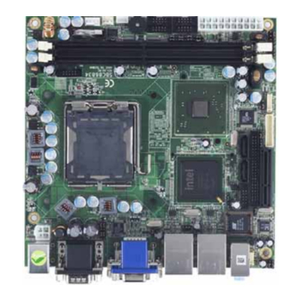
SBC86834 All-In-One Mini ITX Board User’s Manual CHAPTER 1 INTRODUCTION ® ™ The SBC86834, a Mini ITX board, supports Intel Core 2 Duo, ® ® ® ® Intel Celeron 400 Series, Intel Pentium 4 processor in the ® ® LGA775 Land Grid Array package or Intel Pentium D processor (supports 775-Land package) at FSB 533/800 MT/s (133/200 MHz). -
Page 8: Specifications
SBC86834 All-In-One Mini ITX Board User’s Manual memory, maximum memory capacity up to 2GB. It also features Gigabit/Fast Ethernet, two serial ATA channels for total two Serial ATA hard drives at maximum transfer rate up to 300MB/sec, six USB 2.0 high speed compliant, built-in AC’97 audio codec that can achieve the best stability and reliability for industrial applications. - Page 9 SBC86834 All-In-One Mini ITX Board User’s Manual Serial Ports: Six ports for RS-232 ™ CompactFlash Socket ™ One CompactFlash Type II Socket (Optional) USB Interface Six USB ports with fuse protection and complies with USB Spec. Rev. 2.0 Display CRT connector @ rear I/O over DVI connector from DAC port, DVI-D via Chrontel CH7307C from SDVO below CRT connector One 40-pin connector for 24-bit dual channel LVDS via...
-
Page 10: Utilities Supported
SBC86834 All-In-One Mini ITX Board User’s Manual Utilities Supported Chipset Driver Ethernet Driver Graphic Driver Audio Driver Intel Matrix Storage manager Introduction... -
Page 11: Chapter 2 Jumpers And Connectors
SBC86834 All-In-One Mini ITX Board User’s Manual CHAPTER 2 JUMPERS AND CONNECTORS Board Dimensions and Fixing Holes Component Side Jumpers and Connectors... - Page 12 SBC86834 All-In-One Mini ITX Board User’s Manual Solder Side Jumpers and Connectors...
-
Page 13: Board Layout
SBC86834 All-In-One Mini ITX Board User’s Manual Board Layout Component Side Jumpers and Connectors... - Page 14 SBC86834 All-In-One Mini ITX Board User’s Manual Solder Side Jumpers and Connectors...
-
Page 15: Jumper Settings
SBC86834 All-In-One Mini ITX Board User’s Manual Jumper Settings Proper jumer settings configure the SBC86834 to meet your application purpose. We are herewith listing a summary table of all jumpers and default settings for onboard devices, respectively. Jumper Default Setting COM2 Mode Select CN4A Pin 1: DCD Short 3-5... -
Page 16: Com1~Com6 Mode Select For Type Jumpers
SBC86834 All-In-One Mini ITX Board User’s Manual 2.3.1 COM1~COM6 Mode Select for Type Jumpers (JP1, JP2, JP5, JP6, JP8, JP9) These jumpers select the COM1 ~ COM6 ports’ DCD and RI mode. Description Function Jumper Setting (JP2) Pin 1=DCD COM1 (CN4B) (Default) Pin 1=5V Pin 9=RI... - Page 17 SBC86834 All-In-One Mini ITX Board User’s Manual Description Function Jumper Setting (JP1) Pin 1=DCD COM2 (CN4A) (Default) Pin 1=5V Pin 9=RI (Default) Pin 9=12V Jumpers and Connectors...
- Page 18 SBC86834 All-In-One Mini ITX Board User’s Manual Description Function Jumper Setting (JP5) COM3 (CN9) Pin 1=DCD (Default) Pin 1=5V Pin 8=RI (Default) Pin 8=12V Jumpers and Connectors...
- Page 19 SBC86834 All-In-One Mini ITX Board User’s Manual Description Function Jumper Setting (JP6) COM4 (CN10) Pin 1=DCD (Default) Pin 1=5V Pin 8=RI (Default) Pin 8=12V Jumpers and Connectors...
- Page 20 SBC86834 All-In-One Mini ITX Board User’s Manual Description Function Jumper Setting (JP9) COM5 (CN13) Pin 1=DCD (Default) Pin 1=5V Pin 8=RI (Default) Pin 8=12V Jumpers and Connectors...
- Page 21 SBC86834 All-In-One Mini ITX Board User’s Manual Description Function Jumper Setting (JP8) COM6 (CN12) Pin 1=DCD (Default) Pin 1=5V Pin 8=RI (Default) Pin 8=12V Jumpers and Connectors...
-
Page 22: Lvds Voltage Select Jumper (Jp15)
SBC86834 All-In-One Mini ITX Board User’s Manual 2.3.2 LVDS Voltage Select Jumper (JP15) This jumper is to select the voltage for LVDS interface. Description Function Jumper Setting LVDS Voltage 3.3V (Default) Select 2.3.3 CMOS Clear Jumpers (JP3) You may need to use this jumper is to clear the CMOS memory if incorrect settings in the Setup Utility. -
Page 23: Audio Output Select Jumper (Jp16)
SBC86834 All-In-One Mini ITX Board User’s Manual 2.3.4 Audio Output Select Jumper (JP16) Description Function Jumper Setting Audio Output Line Out Select (Default) Speak Out 2.3.5 USB Power Select Jumpers (JP4, JP7, JP12) Description Function Jumper Setting USB Power Select JP4, JP12 (Default) +5VSBY... -
Page 24: Compactflash™ Voltage Selection Jumper (Jp14)
SBC86834 All-In-One Mini ITX Board User’s Manual ™ 2.3.6 CompactFlash Voltage Selection Jumper (JP14) This jumper is to select the voltage for CompactFlash interface. Description Function Jumper Setting CompactFlash 3.3V (Default) Voltage Selection This Jumper is optional. It is not mounted as a default design. ™... -
Page 25: Pcie X 4/ Pcie X 1 Select Jumpers (Jp10, Jp11)
SBC86834 All-In-One Mini ITX Board User’s Manual 2.3.8 PCIE x 4/ PCIE x 1 Select Jumpers (JP10, JP11) This jumper is to select the PCIE x 4 or PCIE x 1 interface for PCIE1 Slot. Jumper Description Jumper Setting Description Jumper Setting PCI-E Slot Function... -
Page 26: Connectors
Connectors connect the board with other parts of the system. Loose or improper connection might cause problems. Make sure all connectors are properly and firmly connected. Here is a summary table shows you all connectors on the SBC86834 Series. Connector Label... -
Page 27: Com3~Com6 Port Connectors (Cn9, Cn10, Cn12, Cn13)
SBC86834 All-In-One Mini ITX Board User’s Manual 2.4.1 COM3~COM6 Port Connectors (CN9, CN10, CN12, CN13) Jumper selectable with +5V/12V power capability is on DCD and RI, depending on the jumper setting. Please refer to the RS-232 pin assignment as listed below: Signal Signal Data Carrier Detect... -
Page 28: Vga & Dvi-D Connector (Cn8)
SBC86834 All-In-One Mini ITX Board User’s Manual 2.4.3 VGA & DVI-D Connector (CN8) CN8 is a double deck VGA & DVI-D connector. The upper CN8A is a standard 15-pin DB15 connector for the CRT VGA display. The lower CN8B is a DVI-D connector for the single link digital visual interface display. -
Page 29: Lvds Backlight Connector (Cn23)
SBC86834 All-In-One Mini ITX Board User’s Manual Signal Signal Ground TLC+ TLC- CN8B 2.4.4 LVDS Backlight Connector (CN23) This is a 7-pin connector for inverter on the board that we strongly recommend you to use the matching DF13-7S-1.25C connector. Signal +12V +12V ENABLE... - Page 30 SBC86834 All-In-One Mini ITX Board User’s Manual Signal MDI3+ CN11A MDI3- CN14A MDI2+ MDI2- MDI1+ MDI1- MDI0+ MDI0- Active LED 100 LAN LED(Green)/ 1000 LAN LED(Orange) Signal CN11B USB D2- USB D2+ USB D3- USB D3+ Signal CN14B USB D0- USB D0+ USB D1- USB D1+...
-
Page 31: Lvds Flat Panel Connector (Cn22)
SBC86834 All-In-One Mini ITX Board User’s Manual 2.4.6 LVDS Flat Panel Connector (CN22) Use this 40-pin connector to support single channel 18-/24-bits or dual channel 36-/48-bits LVDS TFT LCD. It is strongly recommended to use the matching JST SHDR-40V-S-B connector. Signal Signal VCCM... -
Page 32: Sata Connectors (Cn17, Cn18)
SBC86834 All-In-One Mini ITX Board User’s Manual 2.4.7 SATA Connectors (CN17, CN18) These SATA connectors are for high-speed SATA interface ports and they can be connected to hard disk devices. Signal SATA_TX+ SATA_TX- SATA_RX- SATA_RX+ 2.4.8 Audio Phone Jack Connector (CN16) After installing onboard audio driver, you may connect speaker to Line Out jack, microphone to MIC in jack. -
Page 33: Usb Connectors (Cn19)
SBC86834 All-In-One Mini ITX Board User’s Manual 2.4.9 USB Connectors (CN19) These Universal Serial Bus (USB) connectors on this board are for installing versatile USB interface peripherals. These are 10-pin standard USB connectors. Signal Signal USB D4- USB D5- USB D4+ USB D5+ Ground (GND) Ground (GND) - Page 34 SBC86834 All-In-One Mini ITX Board User’s Manual ATX Power On/Off Button This 2-pin connector named as Pin 9 and 10 connect the front panel’s ATX power button to the CPU card, which allows users to control ATX power supply to be power on/off. System Reset Switch Pin 11 and 12 can be connected to the case-mounted reset switch that reboots your computer, not turns OFF the power switch.
-
Page 35: Internal Audio Connector (Cn20)
SBC86834 All-In-One Mini ITX Board User’s Manual 2.4.11 Internal Audio Connector (CN20) The board has a 5pin-header connector CN20 for the internal audio interface. After installing the onboard audio driver, you may connect speaker to Line Out jack, microphone to MIC In. Signal LINE_OUT_L LINE_OUT_R... -
Page 36: Atx 12V Power Connector (Cn1)
SBC86834 All-In-One Mini ITX Board User’s Manual 2.4.13 ATX 12V Power Connector (CN1) Connect the power cable to CN1 for +12V ATX power supply. Signal +12V +12V 2.4.14 SMBUS Connector (CN7) Connector CN7 is for SMBUS interface support Signal CLOCK DATA 2.4.15 Keyboard and PS/2 Mouse Connector (CN2) The board provides a keyboard and Mouse interface with a DIN... -
Page 37: Pin Fan Connectors (Cn6)
SBC86834 All-In-One Mini ITX Board User’s Manual 2.4.16 3 Pin Fan Connectors (CN6) You can connect the system cooling fan cable to CN6. Signal Ground +12V Sensor 2.4.17 4 Pin CPU Fan Connector (CN5) You can connect the CPU cooling fan cable to CN5. It is for CPU cooling fan power. -
Page 38: Pci-Express X 4 Slot (Pcie1)
SBC86834 All-In-One Mini ITX Board User’s Manual 2.4.18 PCI-EXPRESS x 4 Slot (PCIE1) PCIE1 connector is for PCI-Express x 4 interface to support PCI- Express x 4 card. Signa Signal Signal Signal A1 N.C +12V +12V +12V A3 +12V +12V A5 N.C SMCLK SMDAT... -
Page 39: Compactflash™ Card Socket (Scn1)
SBC86834 All-In-One Mini ITX Board User’s Manual ™ 2.4.19 CompactFlash Card Socket (SCN1) The board is equipped with a CompactFlash disk type-II socket on the solder side to support an IDE interface CompactFlash disk card with DMA mode supported. The socket is especially designed to avoid incorrect installation of the CompactFlash disk card. -
Page 40: Parallel Ide Connector (Cn21)
SBC86834 All-In-One Mini ITX Board User’s Manual 2.4.20 Parallel IDE Connector (CN21) CN21 is a 44-pin IDE interface connector for standard 2.5” IDE device. Signal Signal Signal Reset # Data 7 Data 8 Data 6 Data 9 Data 5 Data 10 Data 4 Data 11 Data 3... -
Page 41: Com1, Com2 Port Connector (Cn4)
SBC86834 All-In-One Mini ITX Board User’s Manual 2.4.21 COM1, COM2 Port Connector (CN4) CN4 is a double deck D-Sub connector. The upper CN4A is a standard 9-pin DB9 connector for the Serial Port1 RS-232, jumper selectable with the +5V/12V power capability is on DCD and RI, depending on the jumper setting. - Page 42 SBC86834 All-In-One Mini ITX Board User’s Manual MEMO Jumpers and Connectors...
-
Page 43: Chapter 3 Hardware Installation
SBC86834 All-In-One Mini ITX Board User’s Manual CHAPTER 3 HARDWARE INSTALLATION ® Before installing the processor, please access Intel website for more detailed information http://www.intel.com . Installing the Processor The LGA775 processor socket comes with a cover to protect the processor. - Page 44 SBC86834 All-In-One Mini ITX Board User’s Manual 2. Open the cover (C), you can 3. Be careful not to touch the see the contact. contact (D). 4. Remove the plastic cap (E) from the cover. Hardware Insatllation...
- Page 45 SBC86834 All-In-One Mini ITX Board User’s Manual 5. Place the CPU down into the socket. Be careful not to touch the contact. 6. Hold the edges of the CPU, and orientate it as the marked direction (G) down into the socket to match the (H) and (F) locations. Hardware Installation...
- Page 46 SBC86834 All-In-One Mini ITX Board User’s Manual 7. Slightly push down the cover and hook the lever (I~J). The CPU is completely locked. 8. Orientate the CPU cooling fan to fixing holes on the board. Hardware Insatllation...
- Page 47 SBC86834 All-In-One Mini ITX Board User’s Manual 9. Screw the CPU cooling fan onto the board. 10. Make sure the CPU fan is plugged to the CPU fan connector. Hardware Installation...
-
Page 48: Installing The Memory
SBC86834 All-In-One Mini ITX Board User’s Manual Installing the Memory The board supports four 240-pin DDR2 DIMM memory sockets with maximum memory capacity up to 2GB. Please follow steps below to install the memory modules: Push down latches on each side of the DIMM socket. Align the memory module with the socket that notches of memory module must match the socket keys for a correct intallation. -
Page 49: Chapter 4 Hardware Description
Make sure all correct settings are arranged for your installed microprocessor to prevent the CPU from damages. BIOS The SBC86834 Series uses Award Plug and Play BIOS with a single 8Mbit FWH Flash, DMI, Plug and Play. System Memory... -
Page 50: I/O Port Address Map
SBC86834 All-In-One Mini ITX Board User’s Manual I/O Port Address Map ® ® ® The Intel Core™ 2 Duo Processor, Intel Pentium D Processor, ® ® Intel Celeron Processor can communicate via I/O ports. There are total 1KB port addresses available for assignment to other devices via I/O expansion cards. -
Page 51: Interrupt Controller
SBC86834 All-In-One Mini ITX Board User’s Manual Interrupt Controller The SBC86834 Series is a 100% PC compatible control board. It consists of 16 interrupt request lines, and four out of them can be programmable. The mapping list of the 16 interrupt request lines is shown as the following table. - Page 52 SBC86834 All-In-One Mini ITX Board User’s Manual MEMO Hardware Description...
-
Page 53: Chapter 5 Phoenix-Awrad Bios Utility
SBC86834 All-In-One Mini ITX Board User’s Manual CHAPTER 5 PHOENIX-AWARD BIOS UTILITY The Phoenix-Award BIOS provides users with a built-in Setup program to modify basic system configuration. All configured parameters are stored in a battery-backed-up RAM (CMOS RAM) to save the Setup information whenever the power is turned off. -
Page 54: Control Keys
SBC86834 All-In-One Mini ITX Board User’s Manual Control Keys Move cursor to the previous item Up arrow Move cursor to the next item Down arrow Move cursor to the item on the left hand Left arrow Move to the item in the right hand Right arrow Main Menu -- Quit and delete changes into CMOS Status Page Setup Menu and Option Page Setup... -
Page 55: The Main Menu
SBC86834 All-In-One Mini ITX Board User’s Manual The Main Menu Once you enter the Award BIOS CMOS Setup Utility, the Main Menu appears on the screen. In the Main Menu, there are several Setup functions and a couple of Exit options for your selection. Use arrow keys to select the Setup Page you intend to configure then press <Enter>... -
Page 56: Standard Cmos Setup Menu
SBC86834 All-In-One Mini ITX Board User’s Manual Standard CMOS Setup Menu The Standard CMOS Setup Menu displays basic information about your system. Use arrow keys to highlight each item, and use <PgUp> or <PgDn> key to select the value you want in each item. Date The date format is <day>, <date>... - Page 57 SBC86834 All-In-One Mini ITX Board User’s Manual IDE Channel 0/1/2/3 Master/Slave These items identify the types of each IDE channel installed in the computer. There are 45 predefined types (Type 1 to Type 45) and 2 user’s definable types (Type User) for Enhanced IDE BIOS. Press <PgUp>/<+>...
-
Page 58: Advanced Bios Features
SBC86834 All-In-One Mini ITX Board User’s Manual Advanced BIOS Features This section allows you to configure and improve your system, to set up some system features according to your preference. Phoenix-Award BIOS Utility... - Page 59 SBC86834 All-In-One Mini ITX Board User’s Manual CPU Feature Scroll to this item and press <Enter> to view the CPU Feature sub menu. Delay prior to Thermal This filed is used to select the time that would force the CPU to a 50% duty cycle when it exceeds its maximum operating temperature therefore protecting the CPU and the system board from overheating to ensure a safe computing...
- Page 60 SBC86834 All-In-One Mini ITX Board User’s Manual Hard Disk Boot Priority Scroll to this item and press <Enter> to view the sub menu to decide the disk boot priority. Press <Esc> to return to the Advanced BIOS Features page. CPU L1 & L2 Cache These two options speed up memory access.
- Page 61 SBC86834 All-In-One Mini ITX Board User’s Manual Boot Other Device This item allows the user to enable/disable the boot device not listed on the First/Second/Third boot devices option above. The default setting is “Enabled”. Boot Up NumLock Status Set the the Num Lock status when the system is powered on. The default value is “On”.
-
Page 62: Advanced Chipset Features
SBC86834 All-In-One Mini ITX Board User’s Manual OS Select for DRAM >64MB This item allows you to access the memory over 64MB in OS/2. Report No FDD For WIN 95 Select Yes to release an IRQ when the system doesn’t have any floppy drive, for compatibility with Windows 95 logo certification. - Page 63 SBC86834 All-In-One Mini ITX Board User’s Manual PCI-E Compliancy Mode This item allows users to set the version of the PCI Express based on the specification by which the motherboard has to comply. *** VGA Setting *** PEG/Onchip VGA Control Use this item to choose the primary display card.
-
Page 64: Integrated Peripherals
SBC86834 All-In-One Mini ITX Board User’s Manual Integrated Peripherals This section allows you to configure your OnChip IDE Device, Onboard Device and SuperIO Device. Phoenix-Award BIOS Utility... - Page 65 SBC86834 All-In-One Mini ITX Board User’s Manual OnChip IDE Device Scroll to this item and press <Enter> to view the sub menu OnChip IDE Device. IDE HDD Block Mode Block mode is also called block transfer, multiple commands, or multiple sector read/write. If your IDE hard drive supports block mode (most new drives do), select Enabled for automatic detection of the optimal number of block read/writes per sector the...
- Page 66 SBC86834 All-In-One Mini ITX Board User’s Manual IDE Primary/Secondary Master/Slave PIO The four IDE PIO (Programmed Input/Output) fields let you set a PIO mode (0-4) for each of the four IDE devices that the onboard IDE interface supports. Modes 0 to 4 provide successively increased performance.
- Page 67 SBC86834 All-In-One Mini ITX Board User’s Manual Onboard Device Scroll to this item and press <Enter> to view the sub menu Onboard Device. USB Controller Enable this item if you are using the USB in the system. You should disable this item if a higher-level controller is added. USB 2.0 Controller Enable this item if you are using the EHCI (USB2.0) controller in the system.
- Page 68 SBC86834 All-In-One Mini ITX Board User’s Manual Super IO Device Scroll to this item and press <Enter> to view the sub menu Super IO Device. Onboard Serial Port 1/2 Select an address and corresponding interrupt for the serial port. PWRON After PWR-Fail This item enables your computer to automatically restart or return to its operating status.
-
Page 69: Power Management Setup
SBC86834 All-In-One Mini ITX Board User’s Manual Power Management Setup The Power Management Setup allows you to save energy of your system effectively. It will shut down the hard disk and turn OFF video display after a period of inactivity. ACPI Function This item allows you to enable/disable the Advanced Configuration and Power Management (ACPI). - Page 70 SBC86834 All-In-One Mini ITX Board User’s Manual the information of system configuration and open applications/files is saved to main memory that remains powered while most other hardware components turn off to save energy. The information stored in memory will be used to restore the system when a “wake up”...
- Page 71 SBC86834 All-In-One Mini ITX Board User’s Manual Disabled System will never enter SUSPEND mode Defines the continuous idle time before the system entering SUSPEND mode. 1/2/4/6/8/10/2 If any item defined in (J) is enabled & active, 0/30/40 SUSPEND timer will be reloaded Min/1 Hr HDD Power Down If HDD activity is not detected for the length of time specified in this...
-
Page 72: 5.10 Pnp/Pci Configuration Setup
SBC86834 All-In-One Mini ITX Board User’s Manual 5.10 PnP/PCI Configuration Setup This section describes the configuration of PCI (Personal Computer Interconnect) bus system, which allows I/O devices to operate at speeds close to the CPU speed while communicating with other important components. - Page 73 SBC86834 All-In-One Mini ITX Board User’s Manual interrupt to one of the following types in accordance with the type of devices using the interrupt: 1. Legacy ISA Devices compliant with the original PC AT bus specification, requiring a specific interrupt (such as IRQ4 for serial port PCI/ISA PnP Devices compliant with the Plug and Play standard, whether designed for PCI or ISA bus architecture.
-
Page 74: 5.11 Pc Health Status
SBC86834 All-In-One Mini ITX Board User’s Manual 5.11 PC Health Status This section supports hardware monitering that lets you monitor those parameters for critical voltages, temperatures and fan speed of the board. Current SYSTEM Temperature Show you the current system temperature. Current CPU Temperature These read-only fields show the functions of the hardware thermal sensor by CPU thermal diode that monitors the chip blocks to... -
Page 75: Frequency/Voltage Control
SBC86834 All-In-One Mini ITX Board User’s Manual 5.12 Frequency/Voltage Control This section is to control the CPU frequency and Supply Voltage, DIMM OverVoltage and AGP voltage. Auto Detect PCI Clk The enabled item can automatically disable the clock source for a PCI slot without a module, to reduce EMI (ElectroMagnetic Interference). -
Page 76: 5.13 Load Optimized Defaults
SBC86834 All-In-One Mini ITX Board User’s Manual 5.13 Load Optimized Defaults This option allows you to load your system configuration with default values. These default settings are optimized to enable high performance features. To load CMOS SRAM with SETUP default values, please enter “Y”. If not, please enter “N”. -
Page 77: 5.14 Set Supervisor/User Password
SBC86834 All-In-One Mini ITX Board User’s Manual 5.14 Set Supervisor/User Password You can set a supervisor or user password, or both of them. The differences between them are: Supervisor password: You can enter and change the options on the setup menu. User password: You can just enter, but have no right to change the options on the setup menu. -
Page 78: 5.15 Save & Exit Setup
SBC86834 All-In-One Mini ITX Board User’s Manual 5.15 Save & Exit Setup This section allows you to determine whether or not to accept your modifications. Type “Y” to quit the setup utility and save all changes into the CMOS memory. Type “N” to bring you back to the Setup utility. Phoenix-Award BIOS Utility... -
Page 79: 5.16 Exit Without Saving
SBC86834 All-In-One Mini ITX Board User’s Manual 5.16 Exit Without Saving Select this option to exit the Setup utility without saving changes you have made in this session. Type “Y”, and it will quit the Setup utility without saving your modifications. Type “N” to return to the Setup utility. Phoenix-Award BIOS Utility... - Page 80 SBC86834 All-In-One Mini ITX Board User’s Manual MEMO Phoenix-Award BIOS Utility...
-
Page 81: Appendix A Watchdog Timer
SBC86834 All-In-One Mini ITX Board User’s Manual APPENDIX A WATCHDOG TIMER Watchdog Timer Setting After the system stops working for a while, it can be auto-reset by the Watchdog Timer. The integrated Watchdog Timer can be set up in the system reset mode by program. - Page 82 SBC86834 All-In-One Mini ITX Board User’s Manual ; IF to disable WDT: O 2E 30 O 2F 00 ; Can be disable at any time Timeout Value Range 1 to 255 Minute / Second Program Sample 2E, 87 2E, 87 2E, 07 2F, 08 Logical Device 8...
-
Page 83: Appendix Bdigital I/O
SBC86834 All-In-One Mini ITX Board User’s Manual APPENDIX B DIGITAL I/O Digital I/O Software Programming GPI program sample: Read DI1~DI3 Status I 042A You can get a default value is “DF”. GPO program sample: O 2E 87 O 2E 87 O 2E 07 Select Device 8 O 2F 08... - Page 84 SBC86834 All-In-One Mini ITX Board User’s Manual Digital I/O...
-
Page 85: Appendix C Configuring Sata For Raid Function
SBC86834 All-In-One Mini ITX Board User’s Manual APPENDIX C CONFIGURING SATA FOR RAID FUNCTION Configuring SATA Hard Drive(s) for RAID ® Function (Controller: Intel ICH7R only) Please follow up the steps below to configure SATA hard drive(s): (1) Install SATA hard drive(s) in your system. (2) Enter the BIOS Setup to configure SATA controller mode and boot sequence. - Page 86 SBC86834 All-In-One Mini ITX Board User’s Manual (2)-1 Turn on your system and press the Del button to enter BIOS Setup during running POST (Power-On Self Test). If you want to create RAID, just select RAID for SATA Mode (default IDE) under the Integrated Peripherals menu.
- Page 87 SBC86834 All-In-One Mini ITX Board User’s Manual (2)-2 Set CDROM for First Boot Device under the Advanced BIOS Features menu to boot CD-ROM after system restarts (Figure 2). Figure 2 (2)-3 Save and exit the BIOS Setup. (3) Configuring RAID by the RAID BIOS Enter the RAID BIOS setup utility to configure a RAID array.
- Page 88 SBC86834 All-In-One Mini ITX Board User’s Manual (3)-1 After the POST memory testing and before the operating system booting, a message "Press <Ctrl-I> to enter Configuration Utility" (as Figure 3) shows up, accordingly, press <CTRL+ I> to enter the RAID BIOS setup utility. Figure 3 (3)-2 After you press <CTRL+ I>, the Create RAID Volume screen...
- Page 89 SBC86834 All-In-One Mini ITX Board User’s Manual (3)-3 After entering the CREAT VOLUME MENU screen, you can type the disk array name with 1~16 letters (letters cannot be special characters) in the item “Name”. When finished, press ENTER to select a RAID level (as Figure 5). There are two RAID levels, RAID0 and RAID1.
- Page 90 SBC86834 All-In-One Mini ITX Board User’s Manual (3)-5 After setting all the items on the menu, select Create Volume and press ENTER (as Figure 7) to start creating the RAID array. Figure 7 (3)-6 When prompting the confirmation, press “Y“ to create this volume, or “N“...
- Page 91 SBC86834 All-In-One Mini ITX Board User’s Manual After the creation is completed, you can see detailed information about the RAID Array in the DISK/VOLUME INFORMATION section, including RAID mode, disk block size, disk name, and disk capacity, etc. Figure 9 Delete RAID Volume If you want to delete a RAID volume, select the Delete RAID Volume option in Main Menu.
- Page 92 SBC86834 All-In-One Mini ITX Board User’s Manual Figure 10 Please press [ESC] to exit the ICH7MR RAID BIOS utility. Now, you can proceed to install a SATA controller and the operating system. (4) Making a SATA Driver Disk To install the operating system onto a serial ATA hard disk successfully, you need to install the SATA controller driver during the OS installation.
- Page 93 SBC86834 All-In-One Mini ITX Board User’s Manual (4)-2 When this screen pops out, please click the “CONFIRM” button. Configuring SATA for RAID Function...
- Page 94 SBC86834 All-In-One Mini ITX Board User’s Manual (4)-3 When the Driver is written to the floppy disk, the SATA driver disk is completed. (5) Installing the SATA controller driver during the OS installation Now, the SATA driver disk is ready, and BIOS settings configured, you can proceed to install Windows XP onto your SATA hard drive using the SATA driver.
- Page 95 SBC86834 All-In-One Mini ITX Board User’s Manual (5)-1 Restart your system to boot the Windows XP Setup disk, and press F6 button as soon as you see the message "Press F6 if you need to install a 3rd party SCSI or RAID driver" (as Figure 11).
- Page 96 SBC86834 All-In-One Mini ITX Board User’s Manual (5)-3 If the Setup correctly recognizes the driver of the floppy disk, a controller menu (as Figure 13) will appear below. Use the ARROW keys to select Intel(R) 82801GR/GH SATA RAID Controller (Desktop ICH7R/DH) and press ENTER. Then it will begin to load the SATA driver from the floppy disk.
- Page 97 SBC86834 All-In-One Mini ITX Board User’s Manual (5)-4 When the screen appears as below, press ENTER to continue installing the SATA driver through the floppy disk. It will take about one minute to finish the driver installation. Figure 14 After the SATA controller driver installation is completed, you can proceed to install the Windows XP.
- Page 98 SBC86834 All-In-One Mini ITX Board User’s Manual MEMO Configuring SATA for RAID Function...