Table of Contents
Advertisement
Quick Links
Advertisement
Table of Contents
Troubleshooting

Related Manuals for Gateway GATEWAY 955


Summary of Contents for Gateway GATEWAY 955
-
Page 3: Table Of Contents
Gateway Server Manager ........ - Page 4 Telephone support ..........96 Before calling Gateway Technical Support ......96 Telephone support .
- Page 5 Processor ........... . 111 A Server Specifications System specifications .
-
Page 7: Checking Out Your Gateway Server
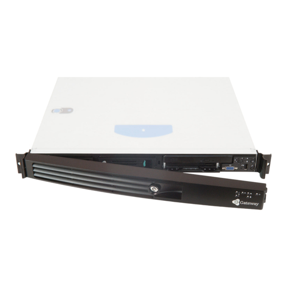
Checking Out Your Gateway Read this chapter to learn: ■ Where drives, ports, jacks, and controls are located ■ Where system board components are located ■ What help resources are available Server... -
Page 8: Front
Chapter 1: Checking Out Your Gateway Server Front SCSI hard drive 1 Control panel LAN 1 activity indicator LAN 2 activity indicator port CD drive SCSI hard drive 2 Power indicator System fault indicator Power button Non-maskable interrupt button www.gateway.com... -
Page 9: Back
Back Low-profile PCI LAN 2 jack expansion port port PS/2 mouse/keyboard port External SCSI LAN 1 jack Full-height PCI expansion USB port System ID indicator Serial RJ-45 port www.gateway.com Back Power connector... -
Page 10: Interior
Chapter 1: Checking Out Your Gateway Server Interior Full-height riser card Low-profile riser card I/O ports Processor 1 Memory slots Processor 2 Power Power supply distribution board www.gateway.com Front panel board Fan module Hot-swap SCSI SCSI backplane hard drives Flex bay... -
Page 11: System Board
System board Connectors PCI riser card (low-profile) SCSI PCI riser card (full-height) Front panel Diskette/ www.gateway.com System board Auxiliary power Fan module power Auxiliary Main power signal... -
Page 12: Getting Help
Use the Server Companion CD to access file utilities, Windows 2000 Server drivers, and documentation for your server and its components. For more information, see Gateway Web site Gateway provides a variety of information on its Web site to help you use your server. Visit the Gateway Web site at ■... -
Page 13: Setting Up Your Server
Setting Up Your Read this chapter to learn how to: ■ Use your server safely ■ Install your server into a cabinet ■ Start and turn off your server ■ Set up your operating system Server... -
Page 14: Setting Up The Hardware
Setting up the hardware To make sure that your working environment is safe: ■ Use a clean, dry, flat, stable surface for your server. Allow at least 6 inches at the rear of the server for cabling and air circulation. ■... -
Page 15: Protecting From Power Source Problems
Surge protectors During a power surge, the voltage level of electricity coming into your server can increase to far above normal levels and cause data loss or server damage. Protect your server and peripheral devices by connecting them to a surge protector, which absorbs voltage surges and prevents them from reaching your server. - Page 16 Most servers can handle this variation, called line noise, without problems. However, some electrical sources include more line noise than normal. Line noise can also be a problem if your server is located near, or shares a circuit with, a device that causes electromagnetic interference, such as a television or a motor.
-
Page 17: Mounting Your Server Into A Cabinet
Mounting your server into a cabinet The cabinet mounting hardware included with your server should be used with standard 4-post cabinets that have front and back vertical posts. The L-shaped cabinet mounting brackets can be used for mid-mounting on a 2-post cabinet, but that procedure is not covered here. - Page 18 Screws Align the holes in a server rail with the tabs on the side of the server, then place the rail against the server and slide the rail as far forward as it will go. Both server rails are identical, so you can use either rail on either side of the server.
- Page 19 Use one of the small screws to fasten the rail to the server, then attach the remaining rail to the other side of the server. Screw Place a disk guide over the disk guide screw hole towards the back of the server.
- Page 20 Chapter 2: Setting Up Your Server Insert a small screw through the disk guide and tighten the screw. Attach the remaining disk guide to the other side of the server. Attach a nut bar to the inside of the two rear cabinet posts using medium screws, but do not completely tighten the screws (leave them loose enough to allow insertion of the cabinet rail in the next step).
- Page 21 Lifting the server and attaching it to the rack is a two-person job. If needed, use an appropriate lifting device. A fully loaded Gateway 955 server weighs about 30 lbs. (13.6 kg). With the front of the server facing you, lift the server, insert it into the cabinet from the front, then position the disk guides so they fit in the cabinet rails.
- Page 22 Chapter 2: Setting Up Your Server Attach one of the server rails to the front cabinet post using two of the medium screws and one nut bar, then attach the remaining rail to the other cabinet post. Warning Screws are required to support the front of the server. You...
-
Page 23: Installing The Front Cover
Insert one of the large screws into the front screw hole on the handle, then insert a spacer onto the part of the screw protruding from the back of the handle. Slide a handle (with its attached screw and spacer) between the server and the server rail. Mounting your server into a cabinet... - Page 24 Chapter 2: Setting Up Your Server Align the screw on the handle with the center hole in the server rail, then tighten the screw. Attach the remaining handle to the other side of the server. Remove the front cover lock keys from the inside of the front cover, then snap on the front cover.
-
Page 25: Removing The Server From A Cabinet
Remove the front cover, if installed. Remove the handles, if installed. While supporting the front of the server, remove the four screws that secure the server rails to the front cabinet posts. While supporting the server, slide the server away from the cabinet until it slides off the cabinet rails. -
Page 26: Starting Your Server
Starting your server Before you start your server for the first time: ■ Make sure that the server and monitor are plugged into a power outlet or surge protector and that the surge protector (if you are using one) is turned ■... - Page 27 You may also need to adjust the monitor’s brightness and contrast controls. If you cannot find the cause of the power loss, contact Gateway ■ Technical Support. For more information, see...
-
Page 28: Understanding The Power-On Self-Test
“Error messages” on page 100 troubleshooting information. Turning off your server Every time you turn off your server, first shut down the operating system. You may lose data if you do not follow the correct procedure. To turn off the server: See the operating system’s documentation or online help for instructions... -
Page 29: Setting Up The Operating System
Setting up the operating system If you ordered your server with the operating system already installed by Gateway, it is completely installed and the basic settings are already configured. See your operating system’s documentation for instructions on configuring advanced settings for your specific network. - Page 30 Chapter 2: Setting Up Your Server www.gateway.com...
-
Page 31: Maintaining Your Server
Maintaining Your Read this chapter to learn how to: ■ Care for your server ■ Record the BIOS configuration ■ Manage your server and network Server... -
Page 32: Caring For Your Server
Avoid dusty or dirty work environments. Dust and dirt can clog the internal mechanisms and can cause the server to overheat. Cleaning your server Keeping your server clean and the vents free from dust helps keep your server performing at its best. Your server cleaning kit could include: ■... - Page 33 If you spill liquid on the keyboard, turn off your server and turn the keyboard upside down to let the liquid drain. Let the keyboard dry completely before trying to use it again.
-
Page 34: Preparing For System Recovery
To record your BIOS configuration: Print the appendix for Restart your server, then press F2 when the Gateway logo screen appears during startup. The BIOS Setup utility opens. Record the BIOS settings on your printout. -
Page 35: System Administration
Gateway Server Manager lets you manage multiple computers on a Windows™ network from a single window, then implement commands and policies across the network with a single action. With Gateway Server Manager, you can run system management tasks which are triggered by certain events or conditions. - Page 36 Setup utility. For information about resetting BIOS passwords, see passwords” on page To set the BIOS security passwords: Restart your server, then press F2 when the Gateway logo screen appears during startup. The BIOS Setup utility opens. Select the Security...
-
Page 37: Using Your Server Companion Cd
Using your Server Companion CD You can use your Server Companion CD to: ■ Install hardware drivers ■ Install programs ■ View server documentation Instructions for using the CD are provided in Using your Server Companion CD Using Your Server Companion... -
Page 38: Identifying Your Server
The System ID indicator is a blue LED that you can turn on to help you locate the correct server. Your server has a System ID indicator in the front and in the back. -
Page 39: Updating The Baseboard Management Controller Firmware
LAN 1 port to send alerts and interact with remote management systems. ■ Providing the main front panel controls (such as power and reset). You should update the BMC firmware when Gateway Technical Support has instructed you to update it. Updating the baseboard management controller firmware www.gateway.com... - Page 40 “Preventing static electricity discharge” on If you do not disconnect the power cord when instructed to in this procedure, the BMC firmware will not update. Pins 1-2 “Opening the server case” on page “Closing the server case” on page www.gateway.com 48, then...
- Page 41 Download the BMC update file from support.gateway.com. Follow the instructions included with the update file. Turn off the server, then disconnect the power cord and wait for the Standby power LED to turn off. Follow the instructions in Move the BMC Write Enable jumper back to pins 2-3.
-
Page 42: Using The System Setup Utility
View sensor data records ■ Set up the server to send alerts for platform events ■ Set up the server for out-of-band (OOB) access through Gateway Server Manager Important Viewing FRU information To view the Field Replaceable Unit (FRU) information: Boot your server from the Server Companion CD, then select from the menu. -
Page 43: Viewing Sensor Data Records
SDRs for that category. Click an SDR. Information for that SDR is displayed. Setting up remote access You can set up the server so that you can perform system management tasks remotely. Setting up remote LAN access To set up remote LAN access: Boot your server from the Server Companion CD, then select from the menu. - Page 44 —The IP address for the server is automatically assigned by the ■ DHCP DHCP (dynamic host control protocol) server on the network. The Host, Gateway, and Subnet Mask boxes in the dialog box are ignored. —Assign the IP address for the server using the Host, Gateway, ■ Static and Subnet Mask boxes in the dialog box.
- Page 45 Access Mode —The EMP is available at any time. ■ Always Active —The EMP is available only when the server is powered down ■ Preboot or is running POST during startup. After the operating system is loaded, a connection cannot be made.
- Page 46 Chapter 3: Maintaining Your Server Setting up paging alerts To set up paging alerts: Boot your server from the Server Companion CD, then select from the menu. The System Setup Utility starts. Utility Install an external modem on the serial RJ-45 port on the back of your server.
- Page 47 Platform Event Manager window. Close Setting up LAN alerts To set up LAN alerts: Boot your server from the Server Companion CD, then select from the menu. The System Setup Utility starts. Utility In the SSU Main window, click...
- Page 48 —The IP address for the server is automatically assigned by the ■ DHCP DHCP (dynamic host control protocol) server on the network. The Host, Gateway, and Subnet Mask boxes in the dialog box are ignored. —Assign the IP address for the server using the Host, Gateway, ■ Static and Subnet Mask boxes in the dialog box.
-
Page 49: Installing Components
Replace the front panel board and power distribution board ■ Replace the system board and CMOS battery You must open your server case to install components. If you are not comfortable with these procedures, get help from a computer service technician or contact Gateway Technical Support. -
Page 50: Preparing To Install Components
Is near a grounded outlet so you can test your server after installation ■ Is near a telephone (in case you need help from Gateway Technical Support). The telephone must be directly connected to a telephone jack and cannot be connected to your server. -
Page 51: Preventing Static Electricity Discharge
■ Wear a grounding wrist strap (available at most electronics stores) and attach it to a bare metal part of the server. You can also touch a bare metal surface on the back of the server with your finger. Warning To prevent risk of electric shock, do not insert any object into the vent holes of the power supply. -
Page 52: Opening The Server Case
45. Make sure you turn off the server, then unplug the power cord and all other cables connected to the server. If the front cover is installed, unlock it, then pull it off. If the server is mounted in a cabinet, remove the server from the cabinet. For instructions, see Warning Place the server on a stable, non-skid surface. - Page 53 Press and hold the panel release button, then slide the top panel toward the back of the server about 1/2 inch. Panel release button Lift the top panel away from the server. www.gateway.com Opening the server case...
-
Page 54: Closing The Server Case
Slide the top panel’s edges into the server. Slide the top panel toward the front of the server until it clicks into place. Reconnect the power cord and all other cables. -
Page 55: Installing Drives
Installing drives Your server’s basic configuration includes one combination CD/diskette drive and as many as three SCSI hard drives. As you prepare to install drives, remember: ■ Before you install a drive, see the drive’s documentation for information on configuring the drive, setting drive jumpers, and attaching cables. - Page 56 Chapter 4: Installing Components While holding the locking handle, pull the drive out of the server. Insert the new drive into the Flex Bay, then press it in until the drive faceplate is flush with the front of the server.
-
Page 57: Installing A Hot-Swap Scsi Hard Drive Into The Flex Bay
To install a hot-swap hard drive into the Flex Bay: Follow the instructions in page Rotate the combination drive’s locking handle up. While holding the locking handle, pull the drive out of the server. “Preventing static electricity discharge” on www.gateway.com Installing drives... - Page 58 Chapter 4: Installing Components Insert the Flex Bay plug into the top left area of the front control panel. The Flex Bay plug comes in your server’s accessory box. Install the hard drive into the hot-swap drive tray. For instructions, see “Installing a hard drive”...
- Page 59 Press the lever closed to lock the drive into place. Reconnect all power cords and peripheral device cables, then turn on the server. After the hard drive is installed and the server is turned on, the hard drive in the Flex Bay is hot-swappable.
-
Page 60: Installing A Hard Drive
Chapter 4: Installing Components Installing a hard drive Use this procedure to add or replace hard drives in the hot-swap bay. Your server supports up to three 1-inch high 3.5-inch SCA SCSI hard drives. You can purchase additional SCSI drives through your Gateway sales or Technical Support representative. - Page 61 Press the green release button on the hot-swap tray lever, then swing the lever open all the way. Pull the tray straight out of the server. www.gateway.com Installing drives...
- Page 62 Screw Screw Screw Screw - OR - If you are adding a new drive, remove the four screws that secure the hard drive spacer to the drive tray, then remove the spacer from the tray. Screw Screw Screw Screw www.gateway.com...
- Page 63 Step Make sure that the tray’s release lever is open, then slide the new drive into the empty hot-swap bay. Close the drive’s release lever. www.gateway.com Installing drives...
-
Page 64: Installing Memory
Modules must be installed in identical pairs. Use only low-profile (LP) 1.2-inch, DDR-266 compliant, SDRAM registered ECC, DIMM memory modules. Install memory first into Bank 1, Bank 2, then Bank 3. If memory is installed incorrectly, your server will not start. Bank 2 Bank 3 www.gateway.com... - Page 65 The tabs on the sides of the memory slot should secure the memory module automatically. Follow the instructions in Turn on the server, then make sure that the operating system completely loads. If you receive an error, see “Preventing static electricity discharge” on “Opening the server case”...
-
Page 66: Installing Pci Expansion Cards
To replace, add, or reseat a PCI expansion card: Follow the instructions in page Follow the instructions in If you are replacing a card, disconnect any cables that are attached to the old card. “Preventing static electricity discharge” on “Opening the server case” on page www.gateway.com... - Page 67 Locate the appropriate riser card, then lift the riser card from the system board by lifting the blue plastic loop and the end of the riser card closest to the front of the server. Pull the card locking clip open, then swing the locking clip away from the riser card.
- Page 68 EMI shield from the riser card by pushing it toward the back of the riser card. Insert the new card into the card slot. You can slightly seesaw the card end-to-end to help insert the card, but do not bend the card sideways. www.gateway.com...
- Page 69 Rotate the card locking clip closed. Connect any cables to the card following the instructions in the card’s documentation. Press the riser card back into the server. Follow the instructions in See the card’s documentation for software installation instructions. Installing PCI expansion cards “Closing the server case”...
-
Page 70: Replacing The Fan Module
To replace the fan module: Follow the instructions in page Follow the instructions in Lift the air baffle away from the server. Unplug the fan module’s power cable from the system board. “Preventing static electricity discharge” on “Opening the server case” on page... - Page 71 Press the module’s release button, then lift the module away from the server. Insert one end of the new fan module under the module guide located on the right side of the case near the processors. www.gateway.com Replacing the fan module Fan module guide...
- Page 72 Insert the air baffle’s mounting post into the mounting post hole. Make sure that the data cable is routed under the baffle. Air baffle mounting post hole Follow the instructions in “Closing the server case” on page www.gateway.com...
-
Page 73: Installing A Processor
Installing a processor The server is compatible with Intel detects the processors each time you turn on the server. Whenever you install new processors, you should first install the most current version of the BIOS. For instructions, see “Updating the BIOS” on page... - Page 74 Remove the fan module. For instructions, see on page Press down on the heat sink locking clip’s lever to detach the clip on the lever’s side, then slide the clip toward the opposite end and remove it from the heat sink. “Replacing the fan module” www.gateway.com...
- Page 75 Continue with the procedure. Rotate the processor release lever a full 135° to release the processor, then lift the processor out of the socket. www.gateway.com Installing a processor...
- Page 76 Place the heat sink on the processor, then press the heat sink locking clips into place. Follow the instructions in If you install two processors onto the system board, the processors must be the same speeds, revision, core voltage, and bus speed. “Closing the server case” on page www.gateway.com...
-
Page 77: Replacing The Power Supply
Only a qualified computer technician should service the power supply. Your server comes with a 3-wire AC power cord fitted with the correct plug style for your region. If this plug does not match the connector on your surge protector, UPS, or wall outlet, do not attempt to modify the plug in any way. - Page 78 Chapter 4: Installing Components Slide the power supply toward the back of the server until the power supply disconnects from the server. www.gateway.com...
- Page 79 Lift the power supply out of the case. Lay the new power supply onto the metal tabs, then slide it toward the front of the server until the back of the power supply is secured behind the metal tabs. Follow the instructions in www.gateway.com...
-
Page 80: Replacing The Scsi Backplane
Follow the instructions in page Follow the instructions in Remove each of the drives from the server, including any drive in the Flex Bay, and make note of which bay you remove each drive from. For instructions, see page 49 Remove the fan module. - Page 81 Align the new backplane’s keyhole slots with the mounting posts on the floor of the server case, then slide the backplane 1/8 inch to the left. mounting post Install the thumbscrew to secure the backplane to the server, then reattach the cables you removed in Step 5.
- Page 82 Chapter 4: Installing Components Install the drives back into the server. Make sure that you replace the drives in the same bays you removed them from in Reinstall the fan module. Follow the instructions in Step “Closing the server case” on page...
-
Page 83: Replacing The Cmos Battery
Replacing the CMOS battery If the server clock does not keep time or the settings in the BIOS Setup utility are not saved when you turn off the server, replace the CMOS battery with an equivalent battery. Warning Danger of explosion if battery is incorrectly replaced. - Page 84 Follow the instructions in Turn on your server, then press F2 when the Gateway logo screen appears during startup. Restore any BIOS settings that you wrote down in Save all your settings and close the BIOS Setup utility.
-
Page 85: Replacing The Power Distribution Board
Follow the instructions in page Follow the instructions in Remove each of the drives from server, including any drive in the Flex Bay. For instructions, see the CD/diskette drive in the Flex Bay” on page Remove the power supply. For instructions, see supply”... - Page 86 Chapter 4: Installing Components Pull the power distribution board toward the front of your server until it disconnects from the system board. Plug the new power distribution board into the system board, then reconnect the power distribution board cables. Reinstall the SCSI backplane, then reinstall the power supply.
-
Page 87: Replacing The Front Panel Board
Replacing the front panel board Follow the instructions in page Follow the instructions in Remove the two cables from the front panel board, then remove the thumbscrew. Replacing the front panel board “Preventing static electricity discharge” on “Opening the server case” on page www.gateway.com... - Page 88 Chapter 4: Installing Components Lift the back of the board 1/8 inch, then pull it toward the back of your server. www.gateway.com...
- Page 89 Warning Forcing the board into place without carefully guiding the light pipes into their holes will damage the light pipes. Install the thumbscrew to secure the board to the server, then reconnect the cables. Follow the instructions in www.gateway.com...
-
Page 90: Replacing The System Board
Disconnect all cables from the system board, noting their locations and orientation. (You will reconnect the cables after you install the new board.) “Preventing static electricity discharge” on “Opening the server case” on page www.gateway.com “Installing memory” “Installing PCI expansion “Replacing the fan module”... - Page 91 Remove the three screws that secure the system board to the server. Screws Remove the eight screws that secure the heat sink brackets to the system board, then remove the brackets. Screws Screws www.gateway.com Replacing the system board Screws Screws...
- Page 92 Chapter 4: Installing Components Slide the system board toward the front of the server. If the board is difficult to move, push on the rear I/O port panel for added leverage. Lift the board away from the case. Insert the new system board into the case, then slide the board toward the back of the case so the board is held under the system board guides.
- Page 93 Reinstall the riser cards. For instructions, see cards” on page Follow the instructions in Turn on your server, then press F2 when the Gateway logo screen appears during startup. Check BIOS settings to make sure that they detect the server’s new hardware, then save your changes (if any) and close the BIOS Setup utility.
- Page 94 Chapter 4: Installing Components www.gateway.com...
-
Page 95: Using The Bios Setup Utility
Using the BIOS Setup Utility Read this chapter to learn how to: ■ Open the BIOS Setup utility ■ Update the BIOS ■ Reset the BIOS settings to their factory defaults ■ Reset the BIOS passwords... -
Page 96: Opening The Bios Setup Utility
Caution To open the BIOS Setup utility: Restart your server, then press F2 when the Gateway logo screen appears during startup. When you select menu items, the Item Specific Help box on the right side of the screen displays specific information about the selection. -
Page 97: Updating The Bios
Gateway, then install the new version from a diskette. To update the BIOS: Print the appendix for Restart your server, then press F2 when the Gateway logo screen appears during startup. Record any custom BIOS settings on your printout. Download the BIOS update from support.gateway.com. -
Page 98: Resetting The Bios
Move the Clear BIOS jumper on the system board. To reset the BIOS using the power and reset buttons: Print the appendix for Restart your server, then press F2 when the Gateway logo screen appears during startup. Record any custom BIOS settings on your printout. -
Page 99: Resetting Bios Passwords
Warning Moving the jumper while the power is on can damage your server. Always turn off the server and unplug the power cord and all other cables before changing the jumper. Place a jumper across the CLR/CMOS pins of jumper J1D4, then remove the jumper. - Page 100 Chapter 5: Using the BIOS Setup Utility www.gateway.com...
-
Page 101: Troubleshooting
Troubleshooting Read this chapter to learn how to: ■ Get telephone support and training ■ Interpret error messages and codes ■ Troubleshoot If the suggestions in this chapter do not correct the problem, see “Telephone support” on page 96 information about how to get help. for more... -
Page 102: Telephone Support
If you have recently installed hardware or software, make sure that you have installed it following the instructions provided with it. If you did not purchase the hardware or software from Gateway, see the manufacturer’s documentation and technical support resources. -
Page 103: Telephone Support
Telephone support Gateway offers a wide range of customer service, technical support, and information services. Telephone numbers You can access the following services through your telephone to get answers to your questions: Resource Service description Fax on Order a catalog of documents on common... -
Page 104: Tutoring And Training
Chapter 6: Troubleshooting Tutoring and training Gateway's Technical Support professionals cannot provide hardware and software training. Instead, Gateway recommends the following training resources. Resource Service description In-store training Our friendly and knowledgeable software at Gateway trainers can teach you how to use the Internet... -
Page 105: Safety Guidelines
Safety guidelines While troubleshooting your server, follow these safety guidelines: ■ Never remove the top panel while your server is turned on and while the modem cable and the power cord is connected. ■ Do not attempt to open the monitor. To do so is extremely dangerous. Even if the power is disconnected, energy stored in the monitor components can be dangerous. -
Page 106: Error Messages
Hard disk controller failure - press F1 to try reboot ■ The drive controller may be defective. Press F1 to try to restart the server. For more information about running diagnostics on your hard drive, see your operating system’s documentation. - Page 107 “The master boot record is corrupted” on page System Event Log Full ■ Clear the event log. To clear or view the event log, restart your server, then open the BIOS Setup utility by pressing and holding F2 while your server restarts. Select the Server menu.
-
Page 108: Troubleshooting
First steps Try these steps first before going to the following sections: ■ Make sure that the power cord is connected to your server and an AC outlet and that the AC outlet is supplying power. ■ If you use a surge protector or a UPS, make sure that it is turned on and is rated to handle the power required by your server. -
Page 109: Battery Replacement
Battery replacement If you have problems after installing a new CMOS battery, try each of the following items, closing the case and restarting the server after each try: ■ Restart your server, then open the BIOS Setup utility by pressing and holding F2 while your server restarts. - Page 110 If the beep code occurs even when all ■ expansion cards have been removed, the system board may be at fault. Contact Gateway Technical Support. If the beep code does not occur when ■ the expansion cards have been removed, one of the cards is causing the problem.
-
Page 111: Bios
■ Turn off your server, then remove the combination drive and push it in again to make sure the drive is seated correctly. For instructions, see “Replacing the CD/diskette drive in the Flex Bay” on page Your CD drive tray does not open ■... -
Page 112: Expansion Cards
The hard drive cannot be accessed, or you receive a “General failure reading drive C” error message ■ If a diskette is in the diskette drive, eject it and restart your server by pressing the reset button. ■ Restart your server by pressing the reset button. -
Page 113: Internet
Make sure that the SCSI controller is enabled in the BIOS Setup utility. ■ Reinstall the device driver. For instructions, see ■ Change the drive’s SCSI address to one that is not being used by your server. For more information about SCSI device configurations, see your drive’s documentation. ■... -
Page 114: Keyboard
Contact your telephone service to get the correct code to temporarily disable the service. Also make sure that the modem dialing properties are set correctly. ■ If you purchased the modem from Gateway, contact Gateway Technical Support. “Installing memory” on page www.gateway.com... - Page 115 53K. Other factors, such as line noise, telephone service provider equipment, or ISP limitations, may lower the speed even further. , then click Start Settings , then click Start icon, then click Modems www.gateway.com Troubleshooting Control Panel . The Control Panel . The Dialing Properties...
-
Page 116: Monitor
Shut down and restart your server. ■ Reinstall the modem device driver. For instructions, see Companion ■ Open your server and reseat the modem. For instructions, see PCI expansion cards” on page Monitor Your server is running but there is no picture ■... -
Page 117: Power
You press the power button, but the server does not turn on ■ If the power button LED is green, the server is turned on, but you may not be seeing an image on the monitor. For monitor troubleshooting, see “Monitor”... - Page 118 Chapter 6: Troubleshooting www.gateway.com...
-
Page 119: A Server Specifications
Server Specifications The following specifications are for the standard configuration. Your server may contain optional equipment. All specifications are subject to change. -
Page 120: System Specifications
System specifications Case size 24.25 × 17 × 11/16 inches (61.6 × 43.2 × 1.75 cm) (without handles) Weight Varies by configuration. A fully loaded server weighs about 30 lbs. (13.6 kg) Fans One fan module, containing five 40 mm fans Ports ■... -
Page 121: System Board Specifications
Dual onboard 10/100/1000 network interface ■ IEEE 850.3u auto-negotiation support ■ Full duplex support ■ SCSI Adaptec AIC-7902W controller ■ Dual-channel Ultra320 LVD SCSI channels ■ Accessible at back panel ■ ACPI ACPI compliance Supports: ■ ■ ■ ■ www.gateway.com System board specifications... -
Page 122: Environmental Specifications
Maximum rate of change: 18°F (10°C) per hour Nonoperating: -55° to 150°F (-48.3° to 65.5°C) Operating: 41° to 95°F (5° to 35°C); derated 0.9°F (0.5°C) for every 1,000 feet (305 meters). Use of 2 GB DIMMs derates the server to 86°F (30°C) Altitude... -
Page 123: Additional Specifications
For more information about your server, such as memory size, hard drive size, and processor type, visit Gateway’s eSupport page at support.gateway.com. The eSupport page also has links to additional Gateway documentation and detailed specifications for your own server. www.gateway.com... - Page 124 Appendix A: www.gateway.com...
-
Page 125: B Bios Settings
For a complete list of viewable BIOS settings, run the BIOS Setup utility. To view all BIOS settings: Restart your server, then press F2 when the Gateway logo screen appears during startup. The BIOS Setup utility opens. - Page 126 Onboard NIC Onboard NIC 1 ROM Onboard NIC Onboard NIC 2 ROM Onboard SCSI Onboard SCSI Onboard SCSI Onboard SCSI ROM Onboard Video PCI SLOT 1B ROM PCI SLOT 1C ROM Serial 1 (DB-9) Address Serial 1 (DB-9) IRQ www.gateway.com Value...
- Page 127 Front Panel USB Extended Memory Test BANK #1 BANK #2 BANK #3 Memory Retest Wake On Ring Wake On LAN/PME PCI-X B Wake On PME PCI-X C Wake On RTC Alarm Boot-time Ping Screen Reset Config Data Num lock www.gateway.com Value...
- Page 128 Power Switch Inhibit NMI Control System Management BIOS Redirection Port ACPI Redirection Band Rate Flow Control Terminal Type Serial Port Connector Clear All Event Logs Event Logging Critical Event Logging Late POST Timeout Fault Resilient Booting www.gateway.com Value...
- Page 129 Hard Disk OS Boot Timeout PXE OS Boot Timeout Assert NMI on PERR Assert NMI on SERR FRB-2 Policy POST Error Pause Boot Monitoring Boot Monitoring Policy 1st Boot Device 2nd Boot Device 3rd Boot Device 4th Boot Device 1st ATAPI CDROM www.gateway.com Value...
- Page 130 Appendix B: www.gateway.com...
-
Page 131: C Safety, Regulatory, And Legal Information
Legal Information Important safety information Your Gateway system is designed and tested to meet the latest standards for safety of information technology equipment. However, to ensure safe use of this product, it is important that the safety instructions marked on the product and in the documentation are followed. - Page 132 The system was dropped or the cabinet is damaged. ■ The system performance changes. Replacement parts and accessories Use only replacement parts and accessories recommended by Gateway. Important Warning Do not use Gateway products in areas classified as hazardous locations. Such areas include patient care areas of medical and dental facilities, oxygen-laden environments, or industrial facilities.
-
Page 133: Regulatory Compliance Statements
Unintentional emitter per FCC Part 15 FCC Part 15 Class A Statement The server is designated as complying with Class A requirements if it bares the following text on the rating label: This device complies with Part 15 of the FCC Rules. Operation is subject to the following two conditions: (1) This device may not cause harmful interference. - Page 134 (1) this device may not cause harmful interference, and (2) this device must accept any interference received, including interference that may cause undesired operation. Caution Changes or modifications not expressly approved by Gateway could void the FCC compliance and negate your authority to operate the product. www.gateway.com...
- Page 135 Ringer Equivalence Numbers of all the devices does not exceed 5. To avoid electrical shock or equipment malfunction do not attempt to make electrical ground connections by yourself. Contact the appropriate inspection authority or an electrician, as appropriate. www.gateway.com...
- Page 136 Appendix C: Laser safety statement All Gateway systems equipped with CD and DVD drives comply with the appropriate safety standards, including IEC 825. The laser devices in these components are classified as “Class 1 Laser Products” under a US Department of Health and Human Services (DHHS) Radiation Performance Standard.
- Page 137 For the latest product updates, consult the Gateway Web site at www.gateway.com. In no event will Gateway be liable for direct, indirect, special, exemplary, incidental, or consequential damages resulting from any defect or omission in this manual, even if advised of the possibility of such damages.
- Page 138 Appendix C: www.gateway.com...
-
Page 139: Index
Boot menu BIOS Setup utility card installing slot location troubleshooting case closing opening Gateway Server Manager Server Companion troubleshooting CD drive installing location troubleshooting cleaning case keyboard screen closing case CMOS battery see battery... - Page 140 DIMM see memory diskette drive connector installing location replacing troubleshooting display troubleshooting documentation Gateway Web site Server Companion CD drive bays location drivers installing drives configuring diskette hard drive hot-swap installing installing diskette RAID replacing...
- Page 141 LED indicators line conditioners lock Kensington location Main menu BIOS Setup utility maintenance cleaning cleaning case cleaning keyboard cleaning screen Gateway Server Manager general guidelines recording BIOS configuration master boot record memory installing location troubleshooting messages modem connection speed troubleshooting...
- Page 142 network jack non-maskable interrupt non-technical support Accounting Sales Warranty opening case operating system setup password resetting BIOS supervisor user PCI card see card ports see connections POST (power-on self-test) power auxiliary connector button cord connector indicator line conditioners main connector protecting from surges reset button source problems...
- Page 143 BIOS configuration System Setup Utility technical support FaxBack support resources Technical Support tips before contacting telephone support training classroom Gateway Learning Libraries Learn@Gateway troubleshooting add-in card battery beep codes BIOS card CD drive diskette drive error messages...
- Page 144 SCSI drive technical support telephone support video turning off server turning on server uninterruptible power supply (UPS) updating BIOS updating the BIOS USB ports internal connector location user password utilities BIOS Setup VGA port voltage regulator location Web site Gateway...