Table of Contents
Advertisement
Quick Links
Advertisement
Table of Contents
Troubleshooting

Related Manuals for Gateway 9715


Summary of Contents for Gateway 9715
-
Page 1: User Guide
Gateway 9715 Server USER GUIDE... -
Page 2: Table Of Contents
Gateway Server Manager ........ - Page 3 Replacing the system board ..........149 www.gateway.com...
- Page 4 Power ............. . 220 www.gateway.com...
- Page 5 Before calling Gateway Customer Care ........
-
Page 6: Checking Out Your Gateway Server
Chapter 1 Checking Out Your Gateway Server • Locating drives, ports, jacks, and controls • Locating system board components • Getting help... -
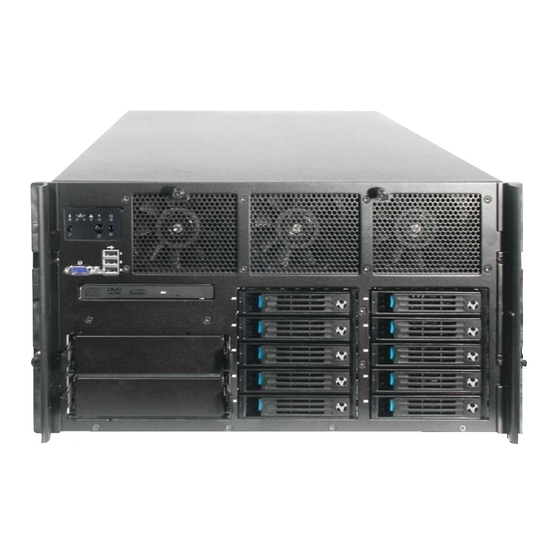
Page 7: Front
Chapter 1: Checking Out Your Gateway Server Front Control Hot swap panel fans (behind USB ports faceplate) Video port CD or drive 5.25-inch Hot-swap drive bays hard drive bays (10) Control panels NIC 2 activity LED Status LED NIC 1 activity LED... -
Page 8: Back
Gb network (optional) ports (2) ID LED USB ports RJ-45 Server Serial port management Monitor port connector ID button Power supply Power supply module latch module latch Power connector Power Power supply Power supply LEDs connector LEDs www.gateway.com... -
Page 9: Interior
Chapter 1: Checking Out Your Gateway Server Interior Center brace CPU Sockets System board Hot-swap Card fans retention clips Fiber Front module retention clip Hot-swap drive bay backplane www.gateway.com... -
Page 10: System Board
Hot plug Express x4 PCI slots 6 and 7 PCI-X 100 (non-hot plug) ROMB RAID activation key ID button ID LED RJ-45 Server management port Memory board C connector Memory board D connector Onboard RAID Fibre channel module connector Cache Memory connector www.gateway.com... -
Page 11: Right Side
Chapter 1: Checking Out Your Gateway Server Right side Front panel connector Power distribution board signal connect DC power connectors CPU 1 socket CPU 2 socket CPU 4 socket CPU 3 socket VRM 9.1 connector (processor cache) Chassis intrusion connector... -
Page 12: Getting Help
For more information, see Using Your System Companion CD. Gateway Web site Gateway provides a variety of information on its Web site to help you use your server. Visit the Gateway Web site at support.gateway.com for: ■... - Page 13 Chapter 1: Checking Out Your Gateway Server www.gateway.com...
-
Page 14: Setting Up Your Server
Chapter 2 Setting Up Your Server • Setting up the hardware • Protecting from power source problems • Mounting your server into a cabinet • Starting and turning off your server • Setting up the operating system • Configuring SCSI features... -
Page 15: Setting Up The Hardware
Lifting the server and attaching it to the rack is a two-person job. If Warning needed, use an appropriate lifting device. A fully loaded Gateway 9715 server weighs about 130 lbs (60 kg). Before attaching cabinet accessories, make sure that the server is Caution turned off and all power cords are unplugged. -
Page 16: Converting To Pedestal Configuration
Converting to pedestal configuration To convert your server to a pedestal configuration, you need a pedestal conversion kit. To order the conversion kit, contact Gateway Customer Care, Gateway Sales, or visit accessories.gateway.com. For more information on contacting Customer Care, see “Telephone support”... - Page 17 Turn the server over so the bottom is facing up, then position the outer cover, supplied with the conversion kit, on the bottom of the chassis. Screw Outer cover Align the screw holes in the outer cover with the holes in the chassis and secure with the six screws provided with the kit. www.gateway.com...
- Page 18 Align the screw holes in the pedestal faceplate with the holes on the front of the chassis, then secure with the Torx screws you previously removed. Insert and partially tighten four screws before inserting the remaining screws, then fully tighten the screws. Faceplate Torx Screw www.gateway.com...
- Page 19 Chapter 2: Setting Up Your Server Reinstall the optional control panel by following the instructions in “Removing and installing the control panel” on page Set the server upright on its casters and reconnect the data and power cables. www.gateway.com...
-
Page 20: Protecting From Power Source Problems
A UPS uses a battery to keep your server running temporarily during a power failure and lets you save your work and shut down your server. You cannot run your server for an extended period of time while using only the UPS. To buy a UPS, visit accessories.gateway.com. www.gateway.com... -
Page 21: Starting Your Server
When you connect peripheral devices to the server, make sure that Caution your server and devices are turned off and the power cords are unplugged. To start the server: ■ Press the power button. Power/sleep LED Power/sleep LED Power button Power button Standard control panel Optional control panel www.gateway.com... - Page 22 Normally, the server fans start and the POST begins running (you can follow the boot progress on the monitor). The SCSI BIOS scan is displayed, followed by the Gateway logo screen. The Gateway logo screen contains the BIOS version and copyright information.
- Page 23 To select which device your server boots from: During server startup, press any key to access the System Options Menu. Press the up and down arrow keys to select from the System Options Boot Manager Menu, then press E . The Boot menu opens. NTER www.gateway.com...
-
Page 24: Understanding The Power-On Self-Test
When you turn on your server, the power-on self-test (POST) routine checks the server memory and components. If POST finds any problems, the server displays error messages. Write down any error messages that you see, then see “Error messages” on page 195 “Post error beep codes” on page 199 for troubleshooting information. www.gateway.com... -
Page 25: Controlling Your Server
The BIOS supports multiple consoles, some of which are in graphics mode and some in text mode. The graphics consoles can display the logo while the text consoles receive the redirected text. Console redirection ends at the beginning of the Legacy OS boot (INT 19h). www.gateway.com... - Page 26 0 = PC-ANSI (the only current terminal type) 1 = VT100 (not implemented, but honored as VT100+) 2 = VT100+ 3 = VT-UTF8 + CDZ0 Inhibit console redirection + CDZ1 Restart console redirection + CDZ2 “Soft” inhibit console redirection, without serial port or modem reset. www.gateway.com...
- Page 27 Set the Terminal Type to ■ VT-UTF8 Press F10, then select to save the changes and exit the BIOS Setup utility. Press E to confirm. The server reboots and console redirection is enabled. NTER Turn off the server and configure the console. www.gateway.com...
- Page 28 ■ Hardware (CTS/RTS) Leave the other settings at their default values ■ Click to accept the settings and enter the hyperterminal screen. Turn on the server. The console starts displaying the redirection after the video on the server synchronizes. www.gateway.com...
-
Page 29: Turning Off Your Server
If you routinely turn off your server (daily or weekly), do not unplug Caution the server or use the On/Off switch on the UPS. Regularly cutting off all power to your server may cause the CMOS battery to fail prematurely. www.gateway.com... -
Page 30: Setting Up The Operating System
Setting up the operating system Setting up the operating system If you ordered your server with the operating system already installed by Gateway, in most cases it is completely installed and the basic settings are already configured. The Windows Small Business Server operating system may require additional installation, depending on the version you ordered. -
Page 31: Initial Hardware Settings
235. For information on the RAID BIOS Console utility, see “Configuring your RAID solutions” on page 163. For information on a specific RAID console for an add-in RAID solution, see the documentation on that hardware which accompanied your server. www.gateway.com... -
Page 32: Configuring Scsi Features
Press F2 to access the menu bar at the top of the screen, then press the H keys to select either the Boot Adapter List Global Properties To access and change the Boot Adapter List: Follow the instructions in “To access the LSI Logic MPT SCSI Setup Utility:” on page www.gateway.com... - Page 33 + or - key to change the status. If you do not want to make any changes, press E to exit the utility. - OR - When you are finished adding or removing boot adapters, press E , The Exit menu NTER screen will open. www.gateway.com...
- Page 34 Use the up and down arrow keys to select options from the list and +/- to change the settings: Pause when boot alert displayed ( ■ Boot information display mode ( ■ Verbose Terse Negotiate with Devices ( ■ Supported Video Mode ( ■ Color Monochrome www.gateway.com...
- Page 35 - To discard your changes and exit the menu. ■ Discard changes then exit this menu - To exit the utility entirely. ■ Exit the Configuration Utility If you made changes, the system will reboot when you exit the utility. www.gateway.com...
- Page 36 Low to High High to Low Removable Media Support ( , or ■ None Boot Drive Only With Media Installed CHS (Cylinder Head Sector) Mapping ( ■ SCSI Plug and Play Mapping Alternate CHS Mapping Spinup Delay (Secs) ( ■ www.gateway.com...
- Page 37 Use the up and down arrow keys to select options from the list and +/- to change the settings: MB/Sec ( ■ MT/Sec ( ■ Data Width ( ■ Scan ID ( ■ Scan Luns >0 ( ■ www.gateway.com...
- Page 38 - To discard your changes and exit the menu. ■ Discard changes then exit this menu - To exit the utility entirely. ■ Exit the Configuration Utility If you made changes, the system will reboot when you exit the utility. www.gateway.com...
- Page 39 Chapter 2: Setting Up Your Server www.gateway.com...
-
Page 40: Managing And Maintaining Your Server
Chapter 3 Managing and Maintaining Your Server • Managing your server and network • Preparing for system recovery • Caring for your server... -
Page 41: System Administration
System administration Gateway Server Manager Gateway Server Manager lets you manage multiple computers on a Windows network from a single window, then implement commands and policies across the network with a single action. With Gateway Server Manager, you can run system management tasks which are triggered by certain events or conditions. - Page 42 The following table shows the LCP menu options: Menu Options Description Configure the Network (LAN channel 1 to 3) Configure TCO NIC server IP address (BMC) ■ Netmask ■ Gateway address ■ Enable LAN channel ■ Inventory View system inventory CPUs ■ DIMMs ■ Drives ■...
- Page 43 Intrusion status Power supply 1 to n Presence ■ Status ■ Fan 1 to n Presence ■ Status ■ Speed ■ HSC 1 to 2 Presence ■ Status ■ Temperatures (all available temperature View all available temperature sensor status sensors www.gateway.com...
-
Page 44: Server Security
To prevent unauthorized use of the server, you can set BIOS startup passwords. Using BIOS security passwords Set up a supervisor password to prevent unauthorized access to the BIOS Setup utility. After you create a supervisor password, you can set up a user password to prevent unauthorized access to the server. www.gateway.com... - Page 45 “Resetting BIOS passwords” on page 161. To set the BIOS security passwords: Restart your server, then press any key when the Gateway logo screen appears during startup. The System Options menu opens. Select , then press E . The BIOS Setup utility opens.
-
Page 46: Identifying Your Server
Press the System ID button. The two blue System ID indicators turn on. System ID Optional control panel Standard control panel indicator LED System ID button System ID indicator LED System ID indicator LED System ID button To turn off the indicator, press the System ID button. www.gateway.com... -
Page 47: Creating A Dos-Bootable System Update Package (Sup) Cd
CD burning software ■ A blank CD To create a DOS-bootable SUP CD: Put a blank CD into your CD burner. Log on to your Internet connection. Go to www.support.gateway.com. Click , then Downloads Browse all downloads Select for Step 1. - Page 48 Creating a DOS-bootable System Update Package (SUP) CD Booting from the SUP CD: Restart your server, then press any key when the Gateway logo screen appears during startup. The System Options menu opens. Select , then press E . The BIOS Setup utility opens.
- Page 49 Exit the System Options menu and let the server continue to boot. After the updates are completed, restart your server, then press any key when the Gateway logo screen appears during startup. The System Options menu opens. Select , then press E .
-
Page 50: Baseboard Management Controller (Bmc)
General fault light control ■ Chassis cooling failure light control ■ Chassis power fault light control ■ Chassis power light control ■ Chassis ID LEDs control ■ ■ System Event Log (SEL) interface ■ Sensor Data Record (SDR) repository interface www.gateway.com... -
Page 51: Intel ® Management Module (Imm) Features
LAN or Serial channel) ■ The IPMI 2.0 serial features are supported. The serial port can be used for console redirection, Terminal-mode CLI, dial paging, Serial Over LAN (SOL), and other management functions. ■ The Intelligent Chassis Management Bus (ICMB) is supported www.gateway.com... -
Page 52: Updating The Bmc Firmware
System is not running or the AC power is off. Updating the BMC firmware You should update the BMC firmware when Gateway Customer Care instructs you to update it. If Gateway Server Manager (GSM) software is installed, it must be Important uninstalled prior to installing or upgrading an IMM module. - Page 53 Chapter 3: Managing and Maintaining Your Server To update the BMC firmware without Boot Block and Force Firmware updates: Download the current SUP CD image from www.support.gateway.com and create a DOS-bootable SUP CD. For information on creating a SUP CD, see “Creating a...
- Page 54 “Closing the server case” on page 72, then reconnect the power cord. Download the current SUP CD image from www.support.gateway.com and create a DOS-bootable SUP CD. For information on creating a SUP CD, see “Creating a DOS-bootable System Update Package (SUP) CD” on page Follow the instructions in “Booting from the SUP CD:”...
-
Page 55: Embedded Web Server
(J1B1) on the IMM module. Follow the instructions in “Closing the server case” on page Restart your server, then press any key when the Gateway logo screen appears during startup. The System Options menu opens. Select , then press E . - Page 56 E NTER The Embedded Web Server checks the privilege level of the user Important before executing every command. The web server will prompt you again if you have logged-in with an insufficient privilege level to execute the requested command. www.gateway.com...
- Page 57 JavaScript. The client script sends a GET or POST request to the server. The server will return either an HTML web page or an XML response. To return an HTML page, use one of the following formats: http://hostname/ipmiPage?cmd=xx.xx.xx.xx.xx?onload=functionName where xx.xx.xx.xx.xx is an IPMI 2.0 command in hexadecimal that is supported by the platform. www.gateway.com...
- Page 58 Argument 1=an error code of 0 or 1 indicates no error Argument 2=an error string associated with the code Argument 3= the response data ipmiHex <ipmiResp completionCode=” YY ”> XX-XX-XX… </ipmiResp> (The completion code YY and the returned data bytes XX are defined in the IPMI specification.) www.gateway.com...
-
Page 59: Fru/Sdr Load Utility
Intel Management Module (IMM). The FRU/SDR must also be updated whenever you update the BIOS. Using the FRU/SDR Load Utility you can also: Determine the product configuration, based on instructions in a master ■ configuration file Display the FRU information ■ www.gateway.com... -
Page 60: The Sel Viewer Utility
■ Each time you update the FRU/SDR, we recommend that you check support.gateway.com for the most current version of the utility. If you find a version that is newer than the one included on the SCCD, download the newer version and use it instead of the SCCD, following the instructions included with the new files. - Page 61 - lets you sort the SEL data by the selected field. Sort By - lets you choose between viewing options, which include hex/text, view/hide, View and screen resolution. - provides SEL Viewer utility help, including a selection of help topics. Help www.gateway.com...
- Page 62 - toggles insert and overwrite editing while in an edit box (indicated by ■ NSERT in the lower-right corner of the box) - to move to the previous screen ■ Exit the utility, remove the CD, then reboot your server. www.gateway.com...
-
Page 63: Using Your System Companion Cd
You can use your System Companion CD to: ■ Install hardware drivers ■ Install programs ■ Access various utilities ■ View server documentation Instructions for using the CD are provided in Using Your System Companion CD, a booklet which is provided with the CD. www.gateway.com... -
Page 64: Preparing For System Recovery
To record your BIOS configuration: Print the appendix for BIOS Settings in this guide. Restart your server, then press any key when the Gateway logo screen appears during startup. The System Options menu opens. Select , then press E . The BIOS Setup utility opens. -
Page 65: Caring For Your Server
Glass cleaner ■ An aerosol can of air with a narrow, straw-like extension ■ Isopropyl alcohol ■ Cotton swabs ■ A tape drive cleaning cartridge (if a tape drive is installed) ■ A CD or DVD drive cleaning kit www.gateway.com... - Page 66 If you use a tape drive to back up your files, regular maintenance will lengthen the life of the drive. To maintain the drive’s reliability: ■ Clean the drive monthly with the cleaning cartridge included with the drive. ■ Remove the tape from the drive whenever the drive is not in use. www.gateway.com...
- Page 67 Chapter 3: Managing and Maintaining Your Server www.gateway.com...
-
Page 68: Installing Components
• Installing and replacing major components You must open your server case to install components. If you are not comfortable with these procedures, get help from a more experienced computer user or computer service technician, or contact Gateway Customer Care. -
Page 69: Preparing To Install Components
Is near a grounded outlet so you can test your server after installation ■ Is near a telephone (in case you need help from Gateway Customer Care). The telephone must be directly connected to a telephone jack and cannot be connected to your server. -
Page 70: Preventing Static Electricity Discharge
Do not lay components on the outside of antistatic bags because only the inside of the bags provide electrostatic protection. ■ Always hold expansion cards by their edges or their metal mounting brackets. Avoid touching the edge connectors and components on the cards. Never slide expansion cards or components over any surface. www.gateway.com... -
Page 71: Opening The Server Case
“Preventing static electricity discharge” on page Turn off the server, then unplug the power cords and all other cables connected to the server. This server may have two power cords. To disconnect internal Warning AC power, you must unplug both power cords. www.gateway.com... -
Page 72: Removing And Installing The Processor Air Baffle
■ Remove or install a processor thermal blank ■ Remove or install a processor ■ Remove or install a processor cache VRM converter ■ Remove or install a CD or DVD drive ■ Remove or install the system board www.gateway.com... - Page 73 Remove or install the front panel I/O board To remove the processor air baffle: Follow the instructions in “Preventing static electricity discharge” on page Follow the instructions in “Opening the server case” on page Lift the processor air baffle from the chassis. Processor air baffle www.gateway.com...
-
Page 74: Removing And Installing The Center Brace
“Closing the server case” on page 72 Removing and installing the center brace The center brace must be removed to: ■ Remove or install a processor core VRM ■ Remove or install the system board ■ Remove or install the SCSI hot-swap backplane www.gateway.com... - Page 75 Move the two center brace locks (located on both sides of and behind the center brace) toward the back of the case to unlock the center brace. Center brace lock Center brace Lift the center brace straight up, out of the case. www.gateway.com...
- Page 76 Move the two center brace locks (located on both sides of and behind the center brace) toward the front of the case to lock the center brace into place. Follow the instructions in “Removing and installing the processor air baffle” on page Follow the instructions in “Closing the server case” on page www.gateway.com...
-
Page 77: Closing The Server Case
Secure the top cover by tightening the two captive screws in the face plate (see “Torque settings” on page 64). Reconnect the power cords and all other cables. www.gateway.com... -
Page 78: Installing Drives
CD, DVD, and tape drives are not hot-swappable, so the server must Caution be turned off and the AC power cords removed prior to installing, removing, or servicing these devices. To remove the CD or DVD drive: Follow the instructions in “Preventing static electricity discharge” on page www.gateway.com... - Page 79 Remove the front panel cable from the SCSI hot-swap backplane by following the instructions in “Replacing the SCSI hot-swap backplane” on page 139. Press the blue release latch on the back of the CD/DVD drive carrier, then slide the drive carrier assembly out the opening in the front panel. www.gateway.com...
- Page 80 Remove the processor air baffle by following the instructions in “Removing and installing the processor air baffle” on page Remove the front panel cable from the SCSI hot-swap backplane by following the instructions in “Replacing the SCSI hot-swap backplane” on page 139. www.gateway.com...
- Page 81 Insert the drive carrier assembly into the front panel of the server until it clicks into place. Plug the SATA and power cables into the SATA-to-IDE converter board on the back of the drive. www.gateway.com...
-
Page 82: Installing A Fixed, Removable-Media Drive In A 5.25-Inch Drive Bay
5.25-inch drive bays. To install a 5.25-inch drive: Follow the instructions in “Preventing static electricity discharge” on page Follow the instructions in “Opening the server case” on page If you are replacing a drive, go to Step - OR - www.gateway.com... - Page 83 Set any jumpers on the new drive. See the drive’s documentation for further instructions. Connect the power and data cables to the drive. For the location of the connectors on the system board, see “System board” on page 5. For additional drive information, see the drive’s documentation. www.gateway.com...
- Page 84 Installing drives Slide the new drive into the drive bay until the drive rails snap into place. Follow the instructions in “Closing the server case” on page www.gateway.com...
-
Page 85: Installing A Hot-Swap Hard Drive
The SCSI backplane (and hot-swap drive bays) support only LVD (Low Voltage Differential) drives. However, the external SCSI connector (on the back of the server) also supports SE (Single Ended) drives. (You can purchase additional drives through your Gateway sales representative. - Page 86 (away from the server), then pull the tray straight out of the server. If you are replacing a hard drive, remove the four screws that secure the hard drive to the drive carrier, then remove the drive from the carrier. www.gateway.com...
- Page 87 Line up the screw holes in the new drive with the holes in the side of the drive carrier, then secure the drive to the carrier with the four screws you removed in Step www.gateway.com...
- Page 88 Make sure that the drive carrier’s release lever is open, then use the lever to slide the new drive into the empty hot-swap bay until it docks in the chassis. Close the drive’s release lever by rotating the lever to the left to latch the drive carrier into position. www.gateway.com...
-
Page 89: Removing And Installing The Control Panel
Push the new control panel into the control panel opening in face plate of the server until it is securely seated. Connect the front panel cable to the back of the front panel board located on the back of the control panel. Follow the instructions in “Closing the server case” on page www.gateway.com... -
Page 90: Memory
Maximum Compatibility, a new memory board can be added to an empty slot. The system will test and initialize the new memory, then inform the operating system. For additional information, see “Hot removal and insertion of memory boards” on page www.gateway.com... - Page 91 LED off - The indicated DIMM is functioning correctly. DIMM 2A Status LED LED on - Error for DIMM slot 2A (J3B2). The indicated DIMM (Orange) is in a fault condition and needs to be replaced. LED off - The indicated DIMM is functioning correctly. www.gateway.com...
- Page 92 For instructions on cold replacement of memory boards, see “Cold removal and installation of memory boards” on page Press the latch on the memory board handle and lift the handle to unlock the memory board. www.gateway.com...
- Page 93 Push the memory board handle down into the locked position. Follow the instructions in “Closing the server case” on page www.gateway.com...
- Page 94 Step Make sure the handle on the memory board is in the open/up position, then align the ends of memory board with the card guides at each end and insert the memory board into the memory board slot. www.gateway.com...
- Page 95 Push the memory board handle down into the locked position. Follow the instructions in “Closing the server case” on page www.gateway.com...
-
Page 96: Installing And Removing Dimms
■ Use only DDR2 DIMMs. No other DIMMs will fit into the DIMM sockets. ■ Use only DIMMs with gold-plated edge connectors. ■ The maximum DIMM height is 1.75-inches (4.445 cm). Do not install DIMMs that exceed this height. www.gateway.com... - Page 97 “Preventing static electricity discharge” on page Follow the instructions in “Opening the server case” on page Remove the memory board or memory board air baffle from the system board by following the instructions in “Installing and removing memory boards” on page www.gateway.com...
- Page 98 Use extreme care when installing DIMMs. Applying too much pressure can damage the DIMM socket or the DIMM. DIMMs are keyed and can only be installed one way. Hold DIMMs by the edges. Do not touch the gold connectors or the components. www.gateway.com...
- Page 99 Press in the DIMM cover retainer tab. Press down on the DIMM cover until it clicks into place. Install the memory board by following the instructions in “Installing and removing memory boards” on page Follow the instructions in “Closing the server case” on page www.gateway.com...
-
Page 100: Configuring Memory Options
Compatibility Select View Configuration Details Make sure that Configuration Possible indicates Yes. If it indicates No, you may ■ need to install more memory to meet the requirements of the selected configuration. Make sure that Sparing indicates Yes. ■ www.gateway.com... - Page 101 NTER Set the Desired Memory Configuration to RAID. Select View Configuration Details Make sure that Configuration Possible indicates Yes. If it indicates No, you may ■ need to install more memory to meet the requirements of the selected configuration. www.gateway.com...
- Page 102 Make sure that Configuration Possible indicates Yes. If it indicates No, you may ■ need to install more memory to meet the requirements of the selected configuration. Press F10 to save your changes and exit. Press Y to confirm and the server reboots with the changes. www.gateway.com...
-
Page 103: Pci Expansion Cards
PCI-X - Runs at 64-bit/100 MHz - Not hot-swappable PCI-X - Runs at 64-bit/100 MHz - Not hot-swappable PCI slot 1 PCI slot 2 PCI slot 3 PCI slot 4 PCI slot 5 PCI slot 6 PCI slot 7 www.gateway.com... -
Page 104: Hot Installation Or Removal Of Pci Expansion Cards
66, but do not turn off or unplug the server. With the Microsoft Windows operating system open, double-click the Unplug/Eject icon in the taskbar to open the Unplug or Eject Hardware menu. The Unplug or Eject Hardware menu opens. www.gateway.com... - Page 105 Do not touch the contacts on the bottom part of the expansion card. Caution Touching the contacts can cause electrostatic damage to the card. Put the card in an anti-static bag for storage. www.gateway.com...
- Page 106 Do not touch the contacts on the bottom part of the expansion card. Caution Touching the contacts can cause electrostatic damage to the card. Put the card in an anti-static bag for storage. www.gateway.com...
- Page 107 Do not touch the contacts on the bottom part of the expansion card. Caution Touching the contacts can cause electrostatic damage to the card. Change the card jumpers as required (refer to the documentation that accompanied the card), then record the serial number and jumper settings. www.gateway.com...
- Page 108 Enable the new PCI card: If you are using the operating system hot-plug interface wait for the interface to appear on your monitor, then confirm the device to be enabled. - OR - www.gateway.com...
-
Page 109: Cold Installation Or Removal Of Pci Expansion Cards
(see illustration in “To install a hot-swap PCI expansion card:” on page 102). If necessary, remove the expansion slot cover for the slot you are using by sliding it up from inside the chassis. www.gateway.com... - Page 110 Install an expansion slot cover over the empty slot by aligning the cover with the slot from the back of the chassis, then pressing the cover into the slot. Rotate the card retention clip into the chassis to the closed position. Follow the instructions in “Closing the server case” on page www.gateway.com...
-
Page 111: Fibre Channel Module
Green LED Activity Green LED Orange LED Red LED System powered off Prior to firmware initialization Post firmware initialization - OR - Loss of synchronization 1Gbps link established One flash every 4 seconds 1Gbps activity One flash every 4 seconds www.gateway.com... -
Page 112: Operating System Driver Installation And Configuration
Refer to the readme.txt file included with the drive for specific information on installation. For information on driver parameters, refer to Section 2, “Driver Parameters,” in the QLogic document Troubleshooting Guide 2Gbps Fibre Channel Host Bus Adapters, available from download.qlogic.com/manual/17851/FC0056702-00A.pdf. www.gateway.com... -
Page 113: Fibre Channel Hba Manager Software
Remove the memory board or memory board air baffle from slot C by following the instructions in “Installing and removing memory boards” on page If you are replacing a module, disconnect any cables that are attached to the old module. www.gateway.com... - Page 114 Place it in a static-free bag for storage. Install an expansion slot cover by aligning it with the back of the chassis, pressing it into the slot, then rotating the fibre channel retention clip into the closed position on the slot cover. Go to Step www.gateway.com...
- Page 115 Attach any required cables to the fibre channel module. Reinstall the memory board of memory board air baffle by following the instructions “Installing and removing memory boards” on page Follow the instructions in “Closing the server case” on page www.gateway.com...
-
Page 116: Processors
A heat sink must be installed on the processor. Installing a processor Caution without a heat sink could damage the processor. Thermal blanks must be present in all processor sockets where no processor is installed. If a processor is removed, a thermal blank must be installed in the empty socket. www.gateway.com... - Page 117 Follow the instructions in “Opening the server case” on page Remove the processor air baffle by following the instructions in “Removing and installing the processor air baffle” on page Loosen the four captive screws (one on each corner of the heatsink). www.gateway.com...
- Page 118 For instructions on installing a processor, see “To install a processor:” on page 114. Replace the processor air baffle by following the instructions in “Removing and installing the processor air baffle” on page Follow the instructions in “Closing the server case” on page www.gateway.com...
- Page 119 Follow the instructions in “Special handling of Intel Xeon processors” on page 111. Follow the instructions in “Opening the server case” on page Remove the processor air baffle by following the instructions in “Removing and installing the processor air baffle” on page www.gateway.com...
- Page 120 If a processor thermal blank is installed, remove it by loosening the four screws (one at each corner) and lifting the thermal blank from the processor socket. Make sure that the processor release lever is in the open position. www.gateway.com...
- Page 121 Otherwise, applications that detect processor speed could cause problems. If only one processor is installed, it must be installed in the CPU 1 socket. Press the processor locking lever down until it clicks into place. www.gateway.com...
- Page 122 “Processor VRM requirements” on page 118 “Installing and removing VRMs” on page 118). Replace the processor air baffle by following the instructions in “Removing and installing the processor air baffle” on page Follow the instructions in “Closing the server case” on page www.gateway.com...
-
Page 123: Processor Vrm Requirements
Follow the instructions in “Opening the server case” on page Remove the processor air baffle by following the instructions in “Removing and installing the processor air baffle” on page Pull the plastic tabs away from the sides of the VRM socket. www.gateway.com... - Page 124 Remove the processor air baffle by following the instructions in “Removing and installing the processor air baffle” on page Gently spread the retaining clips at each end of the VRM socket causing the VRM to lift from the socket. www.gateway.com...
- Page 125 Follow the instructions in “Preventing static electricity discharge” on page Follow the instructions in “Opening the server case” on page Remove the processor air baffle by following the instructions in “Removing and installing the processor air baffle” on page www.gateway.com...
- Page 126 Forcing the wrong VRM into the socket, or forcing the correct VRM into the socket incorrectly, could result in damage to the VRM or the socket. Make sure the tabs on the sides of the VRM socket close securely. www.gateway.com...
- Page 127 Remove the memory boards or memory board air baffles from memory slots C and D by following the instructions in “Installing and removing memory boards” on page Remove the fibre channel module by following the instructions in “Installing or removing the fibre channel module” on page 108. www.gateway.com...
- Page 128 “Installing and removing memory boards” on page Replace the processor air baffle by following the instructions in “Removing and installing the processor air baffle” on page Follow the instructions in “Closing the server case” on page www.gateway.com...
-
Page 129: Installing An Intel Management Module (Imm)
Chapter 4: Installing Components Installing an Intel Management Module (IMM) To install an Intel Management Module (IMM): Uninstall the Gateway Server Manager (GSM) software from your server. Follow the instructions in “Preventing static electricity discharge” on page Follow the instructions in “Opening the server case”... -
Page 130: Memory
GSM software (from a CD which accompanied your server) and update the FRU/SDR (see “FRU/SDR Load utility” on page 54). When you subsequently reboot your server, the GSM software will take over management of the server. For information on the Embedded Web Server, see “Embedded Web Server” on page www.gateway.com... - Page 131 Remove the processor air baffle by following the instructions in “Removing and installing the processor air baffle” on page Remove the memory board or memory board air baffle from slot C by following the instructions in “Installing and removing memory boards” on page www.gateway.com...
- Page 132 Push the key into the socket until it is below the two retaining clips. Pull the plastic tabs away from the sides of the DIMM socket. If you are replacing a DIMM, remove the old one. www.gateway.com...
- Page 133 “Cold installation or removal of PCI expansion cards” on page 104. Insert the end of a small, flat-bladed screwdriver under the plastic tab on the snap-on plastic retainer holding the RAID activation key on the system board, then gently pry the key from the holder. www.gateway.com...
-
Page 134: Installing And Removing The Smart Battery
Remove the processor air baffle by following the instructions in “Removing and installing the processor air baffle” on page Remove the memory board or memory board air baffle from slot D by following the instructions in “Installing and removing memory boards” on page www.gateway.com... - Page 135 After closing the battery case, route the battery cable through the holder on the side of the chassis. Attach the cable to the BBU connector (J1H1 - 2×10) on the system board. See “System board” on page 5 for the location of the connector. www.gateway.com...
- Page 136 Remove the memory board or memory board air baffle from slot D by following the instructions in “Installing and removing memory boards” on page Disconnect the battery cable from the system board. www.gateway.com...
- Page 137 “Installing and removing memory boards” on page Replace the processor air baffle by following the instructions in “Removing and installing the processor air baffle” on page 67 Follow the instructions in “Closing the server case” on page www.gateway.com...
-
Page 138: Power Subsystem
AC sources fails. The modules are capable of power-safe monitoring. Power supply module LEDs indicate the condition of the module and the AC power source. Power good LED (green) Fault LED (orange) AC OK LED (green) www.gateway.com... -
Page 139: Replacing A Power Supply Module
Possible damage to system components could result if the bay is empty for more than five minutes. If your server is configured with only one power supply module, an active fan blank must be installed in the second power supply module bay. www.gateway.com... - Page 140 With the handle in the open position, slide the new power supply module (or active fan blank) into the power supply module bay until it stops. Push the handle up against the power supply module (or active fan blank) until the thumb tab clicks into place. www.gateway.com...
-
Page 141: Replacing A Power Distribution Board
Remove the SCSI backplane by following the instructions in “Replacing the SCSI hot-swap backplane” on page 139. Disconnect all power cables from the power distribution board, noting their locations and orientation. (You will reconnect the cables after you install the new board.) www.gateway.com... - Page 142 Remove the seven (7) screws securing the power distribution board to the chassis, then lift the board from the chassis and place it in an anti-static bag for storage. Remove the new power distribution board from its package and align it with the seven screw holes on the chassis. www.gateway.com...
- Page 143 149. Reinstall the processor air baffle by following the instructions in “Removing and installing the processor air baffle” on page Follow the instructions in “Closing the server case” on page Connect power to the server and restart. www.gateway.com...
-
Page 144: Replacing The Scsi Hot-Swap Backplane
Remove the center brace by following the instructions in “Removing and installing the center brace” on page Remove the system board by following the instructions in “Replacing the system board” on page 149. Disconnect all cables from the SCSI hot-swap backplane. www.gateway.com... - Page 145 Tilt the SCSI hot-swap backplane back slightly, then lift it from the server and place it in an anti-static bag for storage. www.gateway.com...
- Page 146 Reinstall all PCI expansion cards by following the instructions in “Cold installation or removal of PCI expansion cards” on page 104. Reinstall all memory boards and memory board air baffles by following the instructions in “Installing and removing memory boards” on page www.gateway.com...
- Page 147 67 Follow the instructions in “Closing the server case” on page Reinstall all of the drives into the hot-swap drive bays. Make sure that you replace the drives in the correct order by referring to your notes from Step www.gateway.com...
-
Page 148: Replacing The Front Panel I/O Board
Loosen the blue, captive thumbscrew in the center of the front panel I/O board, then slide the board back until the mounting tabs disengage from the board. Blue, captive thumbscrew Mounting Remove the board from the server and store it in an anti-static bag. www.gateway.com... - Page 149 Make sure that the pins on the front panel I/O board line up correctly Important with the front panel cable connector. Reinstall the processor air baffle by following the instructions in “Removing and installing the processor air baffle” on page Follow the instructions in “Closing the server case” on page www.gateway.com...
-
Page 150: Replacing A Hot-Swap Fan
“Preventing static electricity discharge” on page Follow the instructions in “Opening the server case” on page 66, but do not unplug or turn off the server. Locate the fan to be replaced. An orange LED indicates a failed fan. Fan LED www.gateway.com... - Page 151 Orient the new fan in the same direction as the old fan (and existing fans), then insert the new fan into the fan slot until it snaps into place. Wait for the new fan to spin up, then follow the instructions in “Closing the server case” on page www.gateway.com...
-
Page 152: Replacing The Cmos Battery
Locate the old battery on the system board and note its orientation. You will need to install the new battery the same way. Place your finger on the edge of the battery, between the two smaller prongs that hold the battery in place. www.gateway.com... - Page 153 Follow the instructions in “Closing the server case” on page Turn on the server. Press any key when the Gateway logo screen appears during startup. The System Options menu opens. Select the BIOS Setup utility, then press E . The BIOS Setup utility opens.
-
Page 154: Replacing The System Board
Remove the PCI slot dividers by pushing the release latches, then lifting the dividers from the chassis. Disconnect the power and data cables from the system board, noting their locations and orientation. (You will reconnect the cables after you install the new board.) www.gateway.com... - Page 155 Lift the system board from the chassis and place it in an anti-static bag for storage. Set the new system board into the chassis with the processor sockets toward the front and the I/O connectors toward the back. www.gateway.com...
- Page 156 Connect the chassis intrusion switch cable to the system board. Connect the internal SCSI connector to the system board. Install the plastic PCI dividers onto the system board. Install the center brace by following the instructions in “Removing and installing the center brace” on page www.gateway.com...
- Page 157 Connect any remaining cables to the system board. Follow the instructions in “Closing the server case” on page Turn on your server. Press any key when the Gateway logo screen appears during startup. The System Options menu opens. Select the , then press E .
-
Page 158: Using The Bios Setup Utility
Chapter 5 Using the BIOS Setup Utility • Opening the BIOS Setup utility • Updating the BIOS • Resetting the BIOS settings to their factory defaults • Resetting the BIOS passwords... -
Page 159: Opening The Bios Setup Utility
Settings” on page 235. To open the BIOS Setup utility: Restart your server. At the Gateway Logo screen, press any key to access the System Options menu. The System Options menu opens. Select the , then press E . The BIOS Setup utility opens. -
Page 160: Updating The Bios
Updating the BIOS Updating the BIOS If you need a new version of the BIOS, you can download the BIOS update from Gateway, then install the new version from a diskette. To update the BIOS: Print the appendix for BIOS Settings in this guide. -
Page 161: Recovering The Bios
Copy the BIOS update file to the root directory of the recovery media ■ Edit the autoexec.bat file on the recovery media to automatically run the BIOS ■ update. For example, add this line to the autoexec.bat file: iflash64.exe shw4.cap /u /ni www.gateway.com... - Page 162 One beep indicates that the recovery media is valid and that the flash update has started. The system BIOS initializes the text console and display the progress of the recovery. The update will take approximately two minutes and completion will be indicated by two beeps and a completion message on the screen. www.gateway.com...
-
Page 163: Resetting The Bios
Your server has three options available to recover the default configuration. To recover the default BIOS settings using the BIOS Setup utility: Restart your server. Access the System Options menu by pressing any key when the Gateway logo screen appears during startup. The System Options menu opens. Select , then press E . - Page 164 Remove the bootable USB disk-on-key or CD. Turn off the server, then disconnect the power cords and all other cables connected to the server. Follow the instructions in “Opening the server case” on page Place the jumper back onto pins 1-2. www.gateway.com...
- Page 165 While continuing to hold down the Reset button, press the Power button. Release both buttons at the same time. The BIOS reverts to the default settings. Check to make sure that the custom settings previously recorded and Important entered are not causing the application problems before resetting the BIOS. www.gateway.com...
-
Page 166: Resetting Bios Passwords
Follow the instructions in “Closing the server case” on page Reconnect the power cords and turn on the server. The BIOS password(s) is cleared. Turn off the server, then disconnect the power cords and all other cables connected to the server. www.gateway.com... - Page 167 Chapter 5: Using the BIOS Setup Utility Follow the instructions in “Opening the server case” on page Place the jumper back onto pins 1-2. Follow the instructions in “Closing the server case” on page www.gateway.com...
-
Page 168: Configuring Your Raid Solutions
Chapter 6 Configuring your RAID solutions • Configuring the ROMB RAID solution... -
Page 169: Introduction
“Configuring your ROMB RAID solution with the RAID BIOS Console configuration utility” on page 165, or “Configuring your ROMB RAID solution with the RAID Web Console” on page 174, depending on how your server is equipped and the configuration options you prefer. www.gateway.com... -
Page 170: Configuring Your Romb Raid Solution With The Raid Bios Console Configuration Utility
Click on this icon to return to the main screen. Click on this icon to return to the previous page Click on this icon to exit the BIOS Console program. Click on this icon to display the adapters that you can select. www.gateway.com... - Page 171 G when the following message appears: Press <Ctrl>-<G> for BIOS Console The BIOS Console opens at the Adapter Selection screen. Select an adapter from the list, then click to begin the configuration process. Start The Configuration Wizard screen opens. www.gateway.com...
- Page 172 Note: Hot spare drives must be designated before starting auto configuration using all available capacity on the disks. Auto Configuration without Redundancy - Configures all available drives as a RAID 0 logical drive. Custom Configuration - Lets you specify configuration options. www.gateway.com...
- Page 173 Chapter 6: Configuring your RAID solutions Select , then click . The Array Definition screen opens. Custom Configuration Next Hold down the C key and click each drive you want included in the array. To undo the changes, click Reclaim www.gateway.com...
- Page 174 - specifies that additional consecutive stripes are read and buffered into ■ Read-ahead cache. This option will improve performance for sequential reads. - specifies that the controller begins using readahead if the two most recent ■ Adaptive disk accesses occurred in sequential sectors. www.gateway.com...
- Page 175 For two arrays to be spannable, they must have the same stripe width and must be consecutively numbered. If these criteria are not met, the utility ignores the Span setting. Spanning lets the logical drive stripe across multiple arrays. Using this option enables the use of RAID 10 and RAID 50. www.gateway.com...
- Page 176 Set the size of the logical drive in Mbytes. The right pane of the logical drive configuration window will list the maximum capacity that can be selected, depending on the RAID level chosen. Click to accept the changes. The console shows you a preview of the Accept configuration. www.gateway.com...
- Page 177 If fast initialization is not selected as the default for the adapter properties, the initialization may take up to two hours to complete. www.gateway.com...
- Page 178 Configuring your ROMB RAID solution with the RAID BIOS Console configuration utility Click the icon on the top menu bar to return to the main configuration screen. Home Select an additional logical drive to configure or exit the BIOS Console Configuration Utility and reboot the server. www.gateway.com...
-
Page 179: Configuring Your Romb Raid Solution With The Raid Web Console
(server) to a RAID array (on that server) and provides the tools to manage the array. It must be installed on each server that contains a RAID controller in order to manage the RAID configuration from within an OS (either locally or remotely) through a browser. www.gateway.com... -
Page 180: Client System Requirements
Run Windows XP, Windows 2000 or Windows Server 2003, Linux, NetWare, OpenServer, or UnixWare (The Windows version of the Web Console is included with the server. Other versions of the Web Console must be downloaded from support.gateway.com. ■ Utilize a browser that supports Java scripting ■... -
Page 181: Registration Server
To enable the registration server feature, ensure that the ‘networking’ Important option is selected during RAID Web Console installation on each RAID Server. Registration servers must have a static IP address. RAID servers that are not registration servers may have static or dynamically configured network addresses. www.gateway.com... - Page 182 On each RAID server to be managed, edit the regserv.dat file located in the directory. Change the localhost entry to the host name of the registration server. The following edited file shows the localhost entry changed to intel, as an example. www.gateway.com...
- Page 183 Edit the hosts file on each RAID server to resolve the registration server IP address. Add the IP address and the host name of the registration server as shown in the following example. Save the file. It will take about two minutes for the change to take effect. www.gateway.com...
- Page 184 IP address of the registration server, such as http://w2k:3570 or http://192.168.1.1:3570. The Local SetPass utility must be used to set a password on each RAID server. SetPass is installed as part of the Web Console installation. www.gateway.com...
-
Page 185: Installing The Windows Web Console
If it is not installed or not of the correct version, the installation program will install the required version of the JRE and then reboot the system. After reboot, the installation process will continue automatically. The Installation Options screen opens. www.gateway.com... - Page 186 Select the destination directory path. The default destination directory is C:\Program Files\RAID Web Console. Click on Next to begin installation. Set and verify the password. The password can be modified by using the SetPass utility located at \\programfiles\webconsole\setpass\. www.gateway.com...
- Page 187 LIST except , and Administrator Backup Operators System Creator Owner In the Permission dialog box, select , then click Replace Permissions On Subdirectories Exit File Manager. Log in as a guest and verify the permission changes. www.gateway.com...
- Page 188 To de-register or re-register in Windows: In Windows XP, Windows 2000, and Windows Server 2003, open the control panel. Click , then click Administrative Tools Services Click to de-register. Stop RAID_Server - OR - Click to re-register. Start RAID_Server www.gateway.com...
-
Page 189: Launching The Web Console
The RAID Web Console initial screen opens. for a remote system: For Example, http://192.168.0.1:3570 For local RAID management: http://localhost:3570 For access to RAID servers listed in the Registration Server Database, use the registration server’s host name or IP address. www.gateway.com... - Page 190 (MCC-IN in this example). The Login screen opens. You will be presented with an option to control read only functions of the RAID controller or full access to the RAID controllers configuration options. You must have the correct rights to manage the RAID controller’s configuration options. www.gateway.com...
- Page 191 Chapter 6: Configuring your RAID solutions Select , enter you password, then click . The Management Options Full Access Submit screen opens. www.gateway.com...
-
Page 192: Configuring Arrays And Logical Drives
Each logical drive has a label (such as LD1), RAID level, and drive capacity. Click Accept to complete the configuration process. You can delete a logical drive by clicking on it in the bottom config view pane and selecting from the right config view pane. Delete www.gateway.com... - Page 193 Open each list to display the options for each parameter, select an option, then click to proceed. If you use Web Console to configure an array on a NetWare server, you cannot use Writeback as the write policy. www.gateway.com...
- Page 194 Drive menu. The Initialize screen has a separate window for each logical drive. A bar graph displays the progress of the initialization. Click Abort if you want to stop the initialization. Repeat this process for each adapter in the system. www.gateway.com...
-
Page 195: Reclaiming Hot Spare Disks
Adding a physical drive to an existing array To add a physical drive to an array: Go to the Config View screen. Highlight the logical drive and select properties from the left pane. Select the drive to add from the pane. Add Physical Drive www.gateway.com... - Page 196 Launching the Web Console Removing a physical drive from an array To selectively remove hard drives from an existing array: Go to the Config View screen. Highlight the logical drive you want to remove, then select from the left pane. Delete www.gateway.com...
- Page 197 Chapter 6: Configuring your RAID solutions www.gateway.com...
-
Page 198: Troubleshooting
Chapter 7 Troubleshooting • Interpreting error messages and codes • Troubleshooting • Getting telephone support and training If the suggestions in this chapter do not correct the problem, see “Telephone support” on page 223 more information about how to get help. -
Page 199: Safety Guidelines
Liquid has been spilled into your server ■ Your server was dropped ■ The case was damaged ■ Instead, unplug your server and contact a qualified computer technician. If your server was damaged during shipment from Gateway, contact Gateway Customer Care. www.gateway.com... -
Page 200: Error Messages
When the System Options menu opens, select the BIOS Setup utility, then press E . When the BIOS Setup utility opens, make sure that the NTER settings are correct. ■ Reset the BIOS. For more information, see “Resetting the BIOS” on page 158. www.gateway.com... - Page 201 System Options menu by pressing any key. When the System Options menu opens, select the BIOS Setup utility, then press E . When the BIOS Setup utility opens, NTER select the menu, then select the menu. Advanced Event Log Control www.gateway.com...
-
Page 202: Troubleshooting
■ If an error message appears on the screen, write down the exact message before calling Gateway Customer Care. ■ Restart your server, then open the System Options menu by pressing any key while your server restarts. When the System Options menu opens, select the BIOS Setup utility, then press E . - Page 203 Chapter 7: Troubleshooting To restart and access the BIOS Setup utility: At the Gateway Logo screen, press any key to access the System Options menu. The System Options menu opens. Select the , then press E . The BIOS Setup utility opens.
-
Page 204: Beep Codes
Unable to boot to diskette ATAPI, codes: EFh, FAh, FBh, or ATAPI CD. Recovery process F4h, FCh, FDh, FFh will retry. Recovery failed Unable to process valid BIOS recovery images. BIOS already passed control to operating system and flash utility. www.gateway.com... -
Page 205: Additional Beep Codes Provided By Intel Management Modules
No processors 1-5-2-3 Processor configuration error or CPU 1 socket is empty. Reseat or replace the failed processor. In a two-processor system, make sure the processors are identical. 1-5-2-4 Front-side bus select configuration error. 1-5-4-2 DC power unexpectedly lost. www.gateway.com... -
Page 206: Led Information
Unlit - Drive is inactive or no ■ drive installed in carrier Memory board Identify condition On top of each Green or For location and description, LEDs (8) of memory board memory board Orange “Memory” on page and DIMMs www.gateway.com... -
Page 207: Diagnostic Post Leds
POST. For the location of these LEDs, see “System board” on page LED reference designator Example: Initialize memory DS7D2 7 (MSB) DS7D3 DS7D4 0x27 DS7D5 DS7D6 DS7D1 DS7D2 DS7D3 0 (LSB) www.gateway.com... - Page 208 PCI Bus 0×50 Enumerating PCI busses 0×51 Allocating resources to PCI busses 0×52 Hot-plug PCI controller initialization 0×53-0×57 Reserved for PCI bus 0×58 Resetting USB bus 0×59 Reserved for USB devices ATA/ATAPI/SATA 0×5A Resetting PATA/SATA bus and all devices www.gateway.com...
- Page 209 Resetting the mouse 0×99 Detecting the mouse 0×9A Detecting the presence of mouse 0×9B Enabling the mouse Fixed Media 0×B0 Resetting fixed media device 0×B1 Disabling fixed media device 0×B2 Detecting presence of a fixed media device (like IDE hard drive) www.gateway.com...
- Page 210 Calling Int 19. One beep unless silent boot is enabled 0×EF Unrecoverable Boot failure/S3 resume failure Runtime Phase/EFI OS Boot 0×F4 Entering sleep state 0×F5 Exiting sleep state 0×F8 OS has requested EFI to close boot services (ExitBootServices ( ) has been called) www.gateway.com...
- Page 211 Crisis recovery has been initiated because of a user request 0×31 Crisis recovery has been initiated by software (corrupt flash) 0×34 Loading crisis recovery capsule 0×35 Handing off control to the crisis recovery capsule 0×3F Unable to complete crisis recovery www.gateway.com...
-
Page 212: Post Error Messages And Handling
Processor 2 disabled Minor Warning 8132 Processor 3 disabled Minor Warning 8133 Processor 4 disabled Minor Warning 8140 Processor 1 failed FRB-3 timer Minor Warning 8142 Processor 2 failed FRB-3 timer Minor Warning 8143 Processor 3 failed FRB-3 timer Minor Warning www.gateway.com... - Page 213 Intel Management Module firmware and Major Pause FRUSDR update required 0197 Processor speeds are mismatched Major Pause 8300 Baseboard Management Controller failed Major Pause self test 8306 Front panel controller locked Minor Warning 8305 Hotswap controller failed Major Pause www.gateway.com...
- Page 214 Memory board A - DIMM2B not configured Major Pause 8528 Memory board B - DIMM1A not configured Major Pause 8529 Memory board B - DIMM1B not configured Major Pause 852A Memory board B - DIMM2A not configured Major Pause www.gateway.com...
- Page 215 Major Pause 855A Memory board D - DIMM2A disabled Major Pause 855B Memory board D - DIMM2B disabled Major Pause 8560 Memory board A - DIMM1A mismatch Major Pause 8561 Memory board A - DIMM 1B mismatch Major Pause www.gateway.com...
- Page 216 Memory board B - DIMM1A correctable Major Pause ECC error 8589 Memory board B - DIMM1B correctable Major Pause ECC error 858A Memory board B - DIMM2A correctable Major Pause ECC error 858B Memory board B - DIMM2B correctable Major Pause ECC error www.gateway.com...
- Page 217 Memory board B - DIMM1B uncorrectable Major Pause ECC error 85AA Memory board B - DIMM2A uncorrectable Major Pause ECC error 85AB Memory board B - DIMM2B uncorrectable Major Pause ECC error 85B0 Memory board C - DIMM1A uncorrectable Major Pause ECC error www.gateway.com...
- Page 218 Memory board D - DIMM1A invalid speed Major Pause 85D9 Memory board D - DIMM1B invalid speed Major Pause 85DA Memory board D - DIMM2A invalid speed Major Pause 85DB Memory board D - DIMM2B invalid speed Major Pause www.gateway.com...
-
Page 219: Bios
Your server does not recognize a CD or DVD, or the CD or DVD drive ■ Restart your server, then open the BIOS Setup utility by pressing any key when the Gateway logo appears. When the System Options menu opens, select BIOS Setup utility then press E . -
Page 220: Diskette Drive
DOS disk in the USB diskette drive. Use FDISK.EXE to delete all of the partition and create a small partition for DOS. Make sure the partition is set to active. Turn the server off, then back on. www.gateway.com... - Page 221 Options menu or that the first boot device is EFI. To correct the problem: At the EFI Shell command prompt, type EXIT to return to the System Options menu. Select from the System Options menu. Boot Manager Select the correct boot device from the list. www.gateway.com...
-
Page 222: Expansion Cards
Plug the USB flash memory device into a USB port on your server. Boot the server. When you see the Gateway Logo screen, press any key to access the System Options menu. When the System Options menu opens, use the down arrow key to select... -
Page 223: Hard Drive
For more information, “PCI expansion cards” on page 98 or your controller card’s documentation. ■ Make sure that the power cable and SCSI cable are attached securely to the drive cage. www.gateway.com... -
Page 224: Internet
Open your server and make sure that the memory modules are installed correctly. For more information, see “Installing and removing DIMMs” on page ■ A memory module may be defective. Check the LEDs on all of the memory boards to make sure no fault LEDs are on. Replace the faulty memory. www.gateway.com... -
Page 225: Monitor
You press the power button, but the server does not turn on ■ If the power button LED is green, the server is turned on, but you may not be seeing an image on the monitor. For monitor troubleshooting, see “Monitor” on page 220. www.gateway.com... -
Page 226: Processor
Make sure that the processor is fully seated in its socket and that the processor has no bent pins. The processor should be recognized automatically if it is installed correctly. ■ If you have upgraded your server with an additional processor(s): www.gateway.com... - Page 227 For more information, see your operating system’s documentation. Check to make sure you added the additional VRMs required for processors 3 and ■ 4 and that they are fully seated in their sockets. See “Processor VRM requirements” on page 118. www.gateway.com...
-
Page 228: Telephone Support
■ Consider using Gateway’s Internet Customer Care. Gateway’s Web site has FAQs, tips, and other technical help. You can also use the Web site to e-mail Customer Care. For more information, visit Gateway’s Customer Care Web site at support.gateway.com. -
Page 229: Telephone Support
Chapter 7: Troubleshooting Telephone support Gateway offers a wide range of customer service, technical support, and information services. Telephone numbers You can access the following services through your telephone to get answers to your questions: Resource Service description How to reach... -
Page 230: A Server Specifications
Appendix A Server Specifications The following specifications are for the standard configuration. Your server may contain optional equipment. All specifications are subject to change. -
Page 231: System Specifications
Red Hat Enterprise Linux 3 (32-bit): Update 4 ■ SuSE Linux Enterprise Server 9 (32-bit and Intel EM64T versions): ■ SuSE Linux Enterprise Server 8: SP3 ■ Compatible with: Windows NT ■ Certifications FCC Class A ■ ■ ■ www.gateway.com... -
Page 232: System Board Specifications
RAM, mirrored to both front and back I/O ports, including: 2D/3D video accelerator ■ Dual DAC for multi-panel support ■ DVI compliant integrated 165MHz TMDS transmitter ■ Resolutions from VGA up to UXGA (1600×1200) ■ Integrated high-resolution TV-out (up to 1024×768) ■ 32-bit PCI host interface ■ www.gateway.com... - Page 233 Two independent 2 GB serial fibre channel ports ■ Supports up to 400 MBps sustained fibre channel data transfer rate ■ Hardware Main logic board sensors: Monitor Voltage sensors ■ Temperature sensors ■ Adaptive fan speed control and fan speed detection ■ www.gateway.com...
-
Page 234: Fibre Channel Card Specifications
FC-TAPE ■ Buffer credits 3 credits available per port (2,112 byte frame payload) Ports Media Multi-mode optical Optics Short wave laser Connectors LC-style optical connectors that support non-OFC, multi-mode fibre optic cabling using small form factor optical transceiver modules www.gateway.com... -
Page 235: Environmental Specifications
Operating: 2.0 g, 11 msec, ½ sine (100 pulses in each direction, on each of three axes) Non-Operating: Trapezoidal, 25 G, two drops on each of six faces Δ V: 175 inches/sec on bottom face drop, 90 inches/sec on the other five faces www.gateway.com... -
Page 236: Electronic Specifications
Keyboard controller IRQ2 Slave controller INTR output. In APIC mode Timer/counter, HPET #0 IRQ3 Serial port A IRQ4 Serial port B IRQ5 Parallel port IRQ6 Diskette controller IRQ8 Real-time clock/HPET#1 in legacy replacement mode IRQ9 Generic, Option for SCI www.gateway.com... - Page 237 USB 1.1 controller 2 PIRQE Option for SCI, TCO, HPET #0,1,2 PIRQF Option for SCI, TCO, HPET #0,1,2 PIRQG Option for SCI, TCO, HPET #0,1,2 PIRQH USB 2.0 EHCI controller 1, Option for SCI, TCO, HPET #0,1,2 Ser IRQ SIO3 www.gateway.com...
-
Page 238: Additional Specifications
Additional specifications For more information about your server, such as memory size, hard drive size, and processor type, visit Gateway’s Support page at support.gateway.com. The Support page also has links to additional Gateway documentation and detailed specifications for your own server. - Page 239 Appendix A: Server Specifications www.gateway.com...
-
Page 240: B Bios Settings
Appendix B BIOS Settings You can print this appendix, then record your custom BIOS settings on the printout. - Page 241 Quiet Boot Enable Enabled Disabled POST Error Pause Enabled Disabled Processor Core Frequency Bus Frequency Processor Retest Enabled Disabled ® Intel Hyper-Threading Enabled Enable Disabled Boot Processor Number Processor #n Information Menu Processor Family Maximum Frequency Cache Size CPUID Register www.gateway.com...
- Page 242 RAID Upgrade Gap Disabled 512 MB 1024 MB 1536 MB 2048 MB 2560 MB 3072 MB 3585 MB 4096 MB Desired Memory Max Performance Configuration Max Compatibility Mirror RAID View Configuration Details Links to View Configuration Details sub-menu on page 242. www.gateway.com...
- Page 243 Enable SATA Controller Enabled Disabled Primary Master Mass Storage Enable On-board SCSI Enabled Disabled RAID Activation Key Installed Not Installed Enable On-board NIC Enabled Disabled Enable On-board NIC ROM Enabled Disabled NIC 1 MAC Address NIC 2 MAC Address www.gateway.com...
- Page 244 Enabled Disabled Address Enable Slot 1 ROM Enabled Disabled Enable Slot 2 ROM Enabled Disabled Enable Slot 3 ROM Enabled Disabled Enable Slot 4 ROM Enabled Disabled Enable Slot 5 ROM Enabled Disabled Enable Slot 6 ROM Enabled Disabled www.gateway.com...
- Page 245 System Serial Number Chassis Part Number Chassis Serial Number BMC Device ID BMC Firmware Revision BMC Device Revision PIA Revision SDR Revision Hot Swap Controller LAN Management LAN Controller n: Static IP Enable Enabled Disabled Host IP Address Router IP Address www.gateway.com...
- Page 246 Administrator Password is (Installed/Not installed) Set Admin Password (Set or clear Admin password) User Password is (Installed/Not installed) Set User Password (Set or clear User password) Password On Boot Disabled Enabled SDR Revision Varies Exit Save Changes and Exit www.gateway.com...
- Page 247 BIOS submenu BIOS 2nd level Setting Value submenu Configure System RAS Performance Sub-Menu View Memory Configuration Details Configuration Information on selected configuration. Max Effective Size Min. Effective Size Configuration Capabilities Configuration Possible Yes/No Sparing (possible) Yes/No Hot Replace (possible) Yes/No www.gateway.com...
- Page 248 BIOS 2nd level Setting Value submenu Console Redirection Sub-Menu COM1 Console Redirection Enable Slot 1 ROM Enabled Disabled Flow Control None RTS/CTS XON/XOFF CTS/RTS + CD Baud Rate 9600 19.2K 38.4K 57.6K 115.2K Terminal Type VT100 VT100+ VT-UTF8 PC-ANSI www.gateway.com...
- Page 249 Appendix B: www.gateway.com...
-
Page 250: C Field Replaceable Unit (Fru) Kits
Appendix C Field Replaceable Unit (FRU) Kits • Available FRU kits... -
Page 251: Available Fru Kits
Certance DDS-4 5.25" 20/40 GB black ■ DDS-4 TBU Blank media ■ TBU cleaning cartridge ■ MFG instruction: SCSI cable for TBU kits ■ For instructions on installing 5.25-inch drives, see “Installing a fixed, removable-media drive in a 5.25-inch drive bay” on page www.gateway.com... - Page 252 Instructions included in the kit ■ Pedestal conversion kit The kit contains the following: Rackmount-to-pedestal conversion kit ■ Gateway custom bezel - pedestal 9715 ■ For installation instructions, see “Converting to pedestal configuration” on page Memory kits Created and managed by Crucial. For installation instructions, see “Installing and removing DIMMs”...
- Page 253 “Installing and removing the ROMB (RAID on Motherboard) activation key and dedicated RAID memory” on page 126. ROMB BBU feature kit RAID smart battery backup unit (BBU). For installation instructions, “Installing and removing the Smart Battery” on page 129. www.gateway.com...
-
Page 254: D Extensible Firmware Interface (Efi) Shell
Appendix D Extensible Firmware Interface (EFI) Shell... -
Page 255: Introduction
The help command provides information about all the commands (help -b) or specific commands (help <command>). For detailed information about the EFI Shell, its commands, and help in developing applications within the EFI environment, refer to Intel’s EFI Developer’s Guide at developer.intel.com/technology/efi. www.gateway.com... -
Page 256: Basic Efi Shell Commands
[address] [size] [;MMIO] Displays the contents of memory dmpstore Dumps the variable store drivers [-b] [-IXXX] Displays drivers drvcfg [-c] [-IXXX] [-f] [-v] [-s] Invokes the driver configuration protocol drvdiag [-c] [-IXXX] [-s] [-e] [-m] Invokes the driver diagnostics protocol www.gateway.com... - Page 257 .nsh file mode [ col row ] Sets or gets the current graphics mode mount BlkDevice [sname[:]] Mounts a file system on a block device mv [src...] [dst] Move one or more files/directories to destination www.gateway.com...
- Page 258 Delays for the specified number of microseconds time [ hh:mm:ss ] Gets or sets the time type [-a] [-u] [-b] file Displays the contents of a file Displays version information vol fs [volume_label] Sets or displays a volume label www.gateway.com...
- Page 259 Appendix D: www.gateway.com...
-
Page 260: E Safety, Regulatory, And Legal Information
Appendix E Safety, Regulatory, and Legal Information • Safety information • Legal and Regulatory Information... -
Page 261: Important Safety Information
Appendix E: Safety, Regulatory, and Legal Information Important safety information Your Gateway system is designed and tested to meet the latest standards for safety of information technology equipment. However, to ensure safe use of this product, it is important that the safety instructions marked on the product and in the documentation are followed. - Page 262 Do not use Gateway products in areas classified as hazardous Important locations. Such areas include patient care areas of medical and dental facilities, oxygen-laden environments, or industrial facilities. To reduce the risk of fire, use only No. 26 AWG or larger Warning telecommunications line cord.
-
Page 263: Regulatory Compliance Statements
Operation of this equipment in a residential area is likely to cause harmful interference, in which case you will be required to correct the interference at your own expense. Changes or modifications not expressly approved by Gateway could Caution void the FCC compliance and negate your authority to operate the product. - Page 264 (1) this device may not cause harmful interference, and (2) this device must accept any interference received, including interference that may cause undesired operation. Changes or modifications not expressly approved by Gateway could Caution void the FCC compliance and negate your authority to operate the product.
- Page 265 The termination on an interface may consist of any combination of devices subject only to the requirement that the sum of the Ringer Equivalence Numbers of all the devices does not exceed 5. www.gateway.com...
- Page 266 Laser safety statement All Gateway systems equipped with CD and DVD drives comply with the appropriate safety standards, including IEC 825. The laser devices in these components are classified as “Class 1 Laser Products” under a US Department of Health and Human Services (DHHS) Radiation Performance Standard. Should the unit ever need servicing, contact an authorized service location.
-
Page 267: Environmental Information
■ In some cases, your “end of life” product may be “traded in” for credit towards the purchase of new Gateway equipment. Call Gateway to see if this program is available in your area. ■... - Page 268 In the interest of continued product development, Gateway reserves the right to make improvements in this manual and the products it describes at any time, without notices or obligation.
- Page 269 Appendix E: Safety, Regulatory, and Legal Information www.gateway.com...
-
Page 270: Index
BIOS recovery beep codes tape drive BIOS Setup utility closing menus case navigating through CMOS battery opening codes passwords beep recording configuration POST progress settings configuring submenus ROMB RAID troubleshooting connections www.gateway.com... - Page 271 POST progress codes environmental specifications diagnostic POST LEDs error messages DIMM POST see memory Exit menu diskette drive BIOS Setup utility installing expansion card location see card replacing troubleshooting display fans troubleshooting location documentation rear Gateway Web site fibre channel module www.gateway.com...
- Page 272 CD or DVD drive center brace Gateway CMOS battery Customer Care DIMMs Learning Libraries diskette drive Web address fibre channel module Gateway Server Manager front panel board heat sink hot-swap backplane hard drive hot-swap cage indicator hot-swap drive LED indicator hot-swap fans...
- Page 273 Main menu network jack BIOS Setup utility maintenance cleaning opening case cleaning case operating system cleaning keyboard setting up cleaning screen Gateway Server Manager general guidelines panel recording BIOS configuration control master boot record Memory local control installing parallel port memory...
- Page 274 Save menu installing BIOS Setup utility removing screen Processor menu cleaning BIOS Setup utility troubleshooting SCSI rack mount kit installing drives rack mounting server SDRAM RAID see memory memory security www.gateway.com...
- Page 275 BIOS Setup utility Customer Care Shell resources tips before contacting slots telephone support card torque settings processor training software fibre channel Gateway Learning Libraries sparing troubleshooting memory add-in card specifications battery electronic beep codes environmental BIOS system board card...
- Page 276 USB flash memory device video turning off server turning on server uninterruptible power supply (UPS) updating BIOS USB ports location user password utility FRU/SDR Load SEL viewer VGA port Web console components quick configuration steps registration server Web site Gateway www.gateway.com...
- Page 277 www.gateway.com...
- Page 278 MAN 9715 SRV USR GDE R0 06/05...