Table of Contents
Advertisement
Quick Links
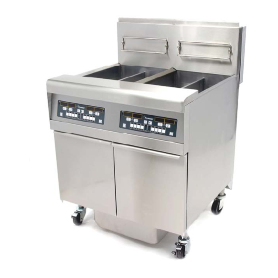
SERVICE MANUAL
FRYMASTER BIPH52/55 AND MPH52/55 SERIES
GAS FRYERS
This equipment chapter is to be
FOR YOUR SAFETY
installed in the Fryer Section of the
Do Not Store or use gasoline or
Equipment Manual.
other flammable vapors and
liquids in the vicinity of this or any
other appliance.
MANUFACTURED
BY
P.O. BOX 51000
SHREVEPORT, LOUISIANA 71135-1000
PHONE: 1-318-865-1711
TOLL FREE: 1-800-551-8633
1-800-24 FRYER
FAX: 1-318-219-7135
Frymaster, L.L.C. 8700 Line Avenue 71106, 5489 Campus Drive 71129
P.O. Box 51000, Shreveport, Louisiana 71135-1000
TEL 318-865-1711 FAX (Parts) 318-219-7140 (Tech Support) 318-219-7135
SERVICE HOTLINE
MAY 2006
PRINTED IN THE UNITED STATES
1-800-24-FRYER
*8196094*
www.frymaster.com
E-mail:
service@frymaster.com
Advertisement
Table of Contents
Troubleshooting

Related Manuals for Frymaster Enodis BIPH52/55


Summary of Contents for Frymaster Enodis BIPH52/55
- Page 1 SHREVEPORT, LOUISIANA 71135-1000 PHONE: 1-318-865-1711 TOLL FREE: 1-800-551-8633 1-800-24 FRYER FAX: 1-318-219-7135 Frymaster, L.L.C. 8700 Line Avenue 71106, 5489 Campus Drive 71129 P.O. Box 51000, Shreveport, Louisiana 71135-1000 TEL 318-865-1711 FAX (Parts) 318-219-7140 (Tech Support) 318-219-7135 SERVICE HOTLINE MAY 2006...
- Page 2 DIRECTLY FROM FRYMASTER DEAN, OR ANY OF ITS AUTHORIZED SERVICE CENTERS, AND/OR THE PART BEING USED IS MODIFIED FROM ITS ORIGINAL CONFIGURATION, THIS WARRANTY WILL BE VOID. FURTHER, FRYMASTER DEAN AND ITS AFFILIATES WILL NOT BE LIABLE FOR ANY CLAIMS, DAMAGES OR EXPENSES INCURRED BY THE CUSTOMER WHICH ARISE DIRECTLY OR INDIRECTLY, IN WHOLE OR IN PART, DUE TO THE INSTALLATION OF ANY MODIFIED PART AND/OR PART RECEIVED FROM AN UNAUTHORIZED SERVICE CENTER.
- Page 3 If a flexible gas line is used, an additional restraining cable must be connected at all times when the fryer is in use. The front ledge of the fryer is not a step! Do not stand on the fryer. Serious injury can result from slips or contact with the hot oil.
-
Page 4: Warranty Statement
3. If any parts, except fuses and filter O-rings, become defective during the first year after installation date, Frymaster will also pay straight-time labor costs to replace the part, plus up to 100 miles/160 km of travel (50 miles/80 km each way). - Page 5 Labor is charged to the store. The third year, warranty will cover the part at a reduced cost of $90.00. No labor or handling will be covered. 2. During this warranty period, Frymaster will replace a returned defective cooking computer with a new or factory rebuilt and functionally operative units.
-
Page 6: Table Of Contents
Accessing Fryers for Servicing ... 1-4 Cleaning the Gas Valve Vent Tube ... 1-5 Checking the Burner Manifold Gas Pressure ... 1-5 Measuring Flame Current... 1-7 Replacing Fryer Components... 1-7 1.6.1 Replacing the Controller or the Controller Wiring Harness... 1-7 1.6.2 Replacing the Temperature Probe or High-Limit Thermostat ... - Page 7 1.12 Simplified Wiring Diagrams ... 1-44 1.12.1 BIPH52/55 Series Full Vat... 1-44 1.12.2 BIPH52/55 Series Dual Vat ... 1-45 1.12.3 BIPH52/55 Series Full Vat (Australia and Pacific Rim)... 1-46 CHAPTER 2: Parts List Accessories... 2-1 Cabinetry ... 2-3 2.2.1 Backs, Doors, Flue Caps, Sides, and Top Caps ... 2-3 2.2.2 Filter Cabinet Bases, Casters, Framing, and Related Components ...
-
Page 8: Chapter 1: Service Procedures
BIPH52/55-MPH52/55 SERIES GAS FRYERS CHAPTER 1: SERVICE PROCEDURES Functional Description BIPH52/55 and MPH52/55 Series gas fryers contain a welded stainless steel frypot that is directly heated by a high efficiency infrared burner system requiring approximately 43% less energy than conventional burners to cook the same volume. Self-contained combustion chambers (referred to as “burners”) are fitted into rails attached to the sides of the frypot, one on each side. -
Page 9: Interface Board
This standard interface board is also used in a number of fryer types besides the BIPH52/55 and MPH52/55 Series. The information contained in this section applies to BIPH52/55 and MPH52/55 Series applications ONLY. - Page 10 INTERFACE BOARD 12 VAC TO CPTR J3 PIN 1 GROUND GROUND COMPUTER (12 VAC) J3 PIN 3 COMPUTER RT HT RELAY COMPUTER 12 VDC TO RELAYS COMPUTER LT HT RELAY RT BL RELAY COMPUTER NOT USED NOT USED COMPUTER LT BL RELAY ALR (RIGHT) RT ALARM OUT COMPUTER...
-
Page 11: Thermostats
BIPH52/55 and MPH52/55 Series fryers are also equipped with a high-limit thermostat. In the event that the fryer fails to properly control the oil temperature, the high-limit thermostat prevents the fryer from overheating to the flash point. The high-limit thermostat acts as a normally closed power switch that opens when exposed to temperatures above 425ºF to 450ºF (218ºC to 232ºC). -
Page 12: Cleaning The Gas Valve Vent Tube
3. After servicing is complete, reconnect the unit to the gas supply, reattach restraining devices, and plug in the electrical cords. NOTE: To ensure the safe and efficient operation of the fryer and hood, the electrical plug for the 120-volt line, which powers the hood, must be fully engaged and locked in its pin and sleeve socket. - Page 13 4. On non-CE fryers only, place the gas valve in the ON position. 5. Place the fryer power switch in the ON position. When the burner has lit and burned steadily for at least one minute, compare the gas pressure reading to the pressure for the corresponding gas in the appropriate table below.
-
Page 14: Measuring Flame Current
7. Place the fryer power switch (and the gas valve in non-CE fryers) in the OFF position. Remove the fitting from the pressure tap hole and reinstall the pressure tap plug. Measuring Flame Current When the burner flame is properly adjusted, it will produce a current between 2.5 μA and 3.5 μA. -
Page 15: Replacing The Temperature Probe Or High-Limit Thermostat
7. If the fryer has a built-in filtration system, remove the clevis securing the oil return handle to the oil return operating rod and separate the rod from the handle. -
Page 16: Replacing The Interface Board
This will leave one set of wires, enclosed in spiral wrap, connected to the component box. 14. Remove the box and set it atop the fryer to expose the temperature probe and high-limit thermostat. -
Page 17: Replacing An Ignition Module
1.6.4 Replacing an Ignition Module 1. Disconnect the fryer from the electrical supply. 2. Lift up on the bezel to disengage the tabs on its lower edge from the control panel frame. 3. Remove the top two screws in the upper corners of the control panel. -
Page 18: Replacing Or Cleaning A Combustion Air Blower
1. Disconnect the blower wiring harness, remove the blower assembly mounting nuts, and remove the blower assembly from the fryer. If cleaning the motor, continue with Step 2; otherwise, install the replacement blower, reconnect the wiring harness, and then go to Step 6. - Page 19 5. Reinstall the blower assembly in the fryer and reconnect the wiring disconnected in Step 1. 6. Light the fryer in accordance with the procedure described in Chapter 3, Section 3.1.2 of the BIPH52/55-MPH52/55 Series Gas Fryer Installation and Operation Manual (P/N 819-6087).
- Page 20 7. After the burners have been lit for at least 90 seconds, observe the flames through the burner viewing ports located on each side of the combustion air blower. Left Viewing Port is behind motor. The air/gas mixture is properly adjusted when the burner manifold pressure is in accordance with the applicable table on page 1-6 and the burners display a bright orange-red glow.
-
Page 21: Replacing A Gas Valve
Eliminate any that are found. H. Position the pan rail assembly beneath the fryer and rest the rear end of the rail on the cabinet frame. Install the two nuts and bolts behind the front face of the rail, but do not tighten them. -
Page 22: Replacing A Burner Assembly
Reconnect the high-limit thermostat wires and drain safety wires to the valve. 7. Reconnect the fryer to the gas supply and open the cut off valve. Apply a solution of soapy water around each connection to check for gas leaks. Eliminate any that are found. -
Page 23: Replacing The Filter Motor, Filter Pump, Or Filter Pump Solenoid Valve
13. Reverse steps 1 through 9 to reassemble the components. 14. Fill the frypot with oil. Turn the fryer on, turn off or bypass the melt cycle, and operate the unit for at least 10 minutes. 15. Visually examine the burner flame. The color and intensity on both sides should be the same. -
Page 24: Replacing The Frypot
4. At the rear of the fryer, unplug the left connector (as viewed from the rear of the fryer) from the transformer box. Using a pin pusher, push the pump solenoid valve wires from Pins 7 and 9. - Page 25 Cut any ties that prevent the box from being pulled out of the control panel frame. 11. Carefully pull the box clear of the frame and rest it atop the fryer. 12. Using a pin pusher, remove the temperature probe and high-limit thermostat wires from the plugs or terminals, marking each wire to facilitate re-assembly.
-
Page 26: Replacing Frypot Insulation And/Or Upper Burner Rails
17. Remove the screws in the back panel and inside the flue cap at each end that secure the flue cap to the fryer and lift it clear of the fryer. 18. Disconnect the oil return line(s) from the frypot to be removed. - Page 27 8. Remove the inner upper combustion chamber insulation retainer and insulation (8). 9. Remove the rear lower combustion chamber retainers, back, and insulation (9). NOTE: Full-vat units have two-piece backs and four retainers. Dual-vat units have one-piece backs and two retainers.
- Page 28 1-21...
- Page 29 11. Remove the upper burner rails (11). NOTE: For the following steps, refer to the frypot exploded view on page 1-24 for component identification. 12. Remove any residual insulation, sealant, and/or oil from the exterior of the frypot. 13. Place the “L” shaped pieces of the combustion chamber insulation (1) in the front and rear corners of both upper rail-retaining slots.
- Page 30 24. Verify that the burners are flush with the front edge of the burner rails. Remove the excess burner insulation by cutting with a knife or diagonal pliers. Do not try to tear the insulation! 25. Insert the upper front insulation (10) into its retainer (11), making sure that the holes in each piece are aligned with one another.
- Page 31 1-24...
-
Page 32: Troubleshooting And Problem Isolation
tripped. - Page 33 CE or Non-CE Standard found in Section 2.3 of the BIPH52/55-MPH52/55 Series Gas Fryer Installation and Operation Manual (part number 819-6087), and that the pressure remains constant throughout all hours of usage. Refer to Section 1.4, Checking the Burner Manifold Gas Pressure in this manual for the procedure for checking the pressure of gas supplied to the burner.
- Page 34 With the insulated handle of the screwdriver, hold the shaft near the frame of the fryer as the power switch is placed in the ON position. A strong, blue spark should be generated for at least 4 seconds.
-
Page 35: Computer Malfunctions
The M2000 computer performs the recovery test each time the fryer warms up. An operator can view the results of the test any time the fryer is above the 325ºF (163ºC) point by pressing the button and entering the code 1652. The test results will be displayed in the computer’s LED panel in minutes and seconds. -
Page 36: Filtration Malfunctions
Most problems concerning computers have to do with programming them. There are two common complaints: 1. Fryer constantly displays “HI.” Cause: Setpoint is incorrect or missing. Corrective Action: Check setpoint and refer to the M2000 computer manual for instructions to adjust the setpoint. -
Page 37: Leakage
A pump seized by debris or hard shortening can usually be freed by manually moving the gears with a screwdriver or other instrument as illustrated on the following page. Make sure power to the pump motor is off before trying this. 1. -
Page 38: Troubleshooting Guides
® Loctite PST56765 sealant or equivalent to prevent leakage. In very rare cases, a leak may develop along one of the welded edges of the frypot. When this occurs, the frypot must be replaced. If the sides or ends of the frypot are coated with oil, the most likely cause is spillage over the top of the frypot rather than leakage. - Page 39 i. If 24 VAC is not present, check the fuses. If they are good, the probable causes are failed ignition module(s) or a failed interface board. ignition module with one known to be good to isolate the cause. ii. If 24 VAC is present, the probable cause is a failed interface board. •...
- Page 40 With Interface Board 106-0386 and One 807-3366 (FV) Ignition Module NOTE: Some units may be wired in this manner. IGNITION MODULE PWR (left side) Jumper LED 5 (GV) J3 PIN 9 This switch used only with built-in filtration systems. 24 VOLT CIRCUIT TRANSFORMER J3 PIN 8 FUSE...
- Page 41 With Interface Board 106-0386 and Two 807-3365 (DV) Ignition Modules Heat Relay (K2 Replaceable) 2 (PWR) High Voltage IGNITION Flame Sensor to Ignitor MODULE 1 (GV) J1 PIN 9 HIGH LIMIT SWITCH DRAIN SAFETY SWITCH VALVE LEFT VAT 24 VOLT CIRCUIT TRANSFORMER IGNITION Flame Sensor...
-
Page 42: Troubleshooting The Gas Valve
Section 2.3 of the Installation and Operation manual. 1. If incoming gas pressure is not correct, the probable cause is a problem with the gas supply to fryer. 2. If incoming gas pressure is correct, check the outgoing gas pressure and compare it to the tables on Page 2-4 of the Installation and Operation manual. -
Page 43: Probe Resistance Chart
• If resistance through J3 pins 2 and 6 (J1 pins 2 and 6 for left side of dual unit) is approximately equal to that given in the Probe Resistance Chart for the corresponding temperature, measure the resistance through each of the previously tested pins to ground. 1. -
Page 44: Principal Wiring Connections
1.10 Principal Wiring Connections LINE VOLTAGE (COM) FROM TRANSFORMER BOX LINE VOLTAGE (COM) FROM TRANSFORMER BOX LEFT VAT FROM PROBE J2 PIN 14 PROBE J2 PIN 15 C2 PIN 13 (BL DOWN) C1 PIN 4 (24VAC) NOT USED GAS VALVE C2 PIN 10 (BL UP) GROUND GROUND... -
Page 45: Wiring Diagrams
1.11 Wiring Diagrams 1.11.1 Main SOUND DEVICE SOUND SOUND DEVICE SENSE 2 SENSE 1 ALARM(GND) ALARM VALVE(GND) VALVE 24VAC(GND) 24VAC SPARK 2 (BURNER) SPARK 1 LEFT IGNITOR OIL RETURN HEATER FRONT TO J3 PIN12 Refer to "PRINCIPAL WIRING CONNECTIONS" on Page 1-37 for detail of connection points J1, J2, J3, C2, C3, and C5. -
Page 46: Transformer / Filter Boxes
1.11.2 Transformer / Filter Boxes 1.11.2.1 MPH152/155 Transformer / Filter Box 1-39... - Page 47 1.11.2.2 BIPH252/255 and 452/455 Transformer / Filter Box (Domestic) 1-40...
- Page 48 1.11.2.3 BIPH252/255 and 452/455 Transformer / Filter Box (International) 1-41...
- Page 49 1.11.2.4 BIPH352/355 Transformer / Filter Box (Domestic) Pump Heater Strip Wires 1-42...
- Page 50 1.11.2.5 BIPH352/355 Transformer / Filter Box (International) 1-43...
-
Page 51: Simplified Wiring Diagrams
1.12 Simplified Wiring Diagrams 1.12.1 BIPH52/55 Series Full Vat 1-44... -
Page 52: Biph52/55 Series Dual Vat
1.12.2 BIPH52/55 Dual Vat 1-45... -
Page 53: Biph52/55 Series Full Vat (Australia And Pacific Rim)
1.12.3 BIPH52/55 Series Full Vat (Australia and Pacific Rim) 1-46... -
Page 54: Chapter 2: Parts List
Basket Support Screen, Full Vat (screen w/handle used in place of Item 4) Coupling, Gas Line Female Quick Disconnect 810-0070 ¾-inch 810-0073 1-inch 803-0197 Cleanout Rod, 27-inch (Fryer's Friend) 803-0209 Brush, Frypot 806-3407 Cover, Frypot, Dual Vat 806-3068 Cover, Frypot, Full Vat... - Page 55 ITEM PART # 812-1378 Drain Extension, Non-Filter Full Vat Fryer 812-1374 Drain Extension, Non-Filter Dual Vat Fryer 803-0219 Pad, McDonald’s FPIII Universal Filter 803-0170 Filter Pack, Paper – 100 Sheets 803-0002 Powder, Filter – 80 Packages 826-1157 Kit, Fuse and Fuse Puller (2 Fuses) * Not illustrated.
-
Page 56: Cabinetry
Cabinetry 2.2.1 Backs, Doors, Flue Caps, Sides, Top Caps, Standoffs and Cap-N-Splash Assemblies... - Page 57 Side, Left Standard Cabinet 211-6510SP Stainless Steel 201-6633 Enameled Steel Side, Right Standard Cabinet 212-6510SP Stainless Steel 202-6633 Enameled Steel Top Cap (Cap for 5-staion fryer shown) 824-1310 Single Fryer 824-1357 2-Station Fryer 823-4702 3-Station Fryer 823-4704 4-Station Fryer 823-4706...
- Page 58 ITEM PART # Standoffs 200-6582 Single Fryer 200-6553 2-Station Fryer 200-6554 3-Station Fryer 200-6555 4-Station Fryer 200-6556 5-Station Fryer Cap-N-Splash Assemblies 823-3066 Single Fryer 823-3067 2-Station Fryer 823-3068 3-Station Fryer 823-3070 4-Station Fryer 823-3069 5-Station Fryer 826-1351 Nut Retainer, ¼-20 (Pkg. of 10 – for basket hanger thumbscrew) for Std. Fluecap 809-0171 Thumbscrew, ¼-20 x...
-
Page 59: Filter Cabinet Bases, Casters, Framing, And Related Components
2.2.2 Filter Cabinet Bases, Casters, Framing, and Related Components The 5-station cabinet illustrated is typical of all BIPH52/55 Series Gas filter cabinets. All base and framing components used in BIPH52/55 Gas filter cabinets are identified, but not all components are used in every configuration. - Page 60 ITEM PART # 106-4303 Frame, Control Panel, Two Station, 106-4304 Three-Station, Standard 106-4305 Four-Station, Standard 106-4306 Five-Station, Standard 210-5819 Bezel, Two-Controller 210-6698 Bezel, Three-Controller 210-5046 Bezel, One-Controller 210-5623 Bezel, Blank 900-7730 Brace, Cabinet Top Two-Station 900-9430 Three-Station 900-9318 Four-Station 200-5474 Five-Station 200-5478 Divider, Cabinet...
-
Page 61: Non-Filter Cabinet Bases, Casters, Framing, And Related Components
2.2.3 Non-Filter Cabinet Bases, Casters, Framing, and Related Components The 5-station cabinet illustrated is typical of all MPH52/55 Series Gas non-filter cabinets. All base and framing components used in MPH52/55 Series Gas non-filter cabinets are identified, but not all components are used in every configuration. - Page 62 823-4653 Channel, Side Base Channel, Front Base 200-6616 Single Fryer (also used as rear base channel in single-station fryers) 200-6623 Two-Station (also used as rear base channel in single-station fryers) 200-6624 Three-Station (also used as rear base channel in single-station fryers)
-
Page 63: Controllers
Controllers and Associated Components ITEM PART # Computer, McDonald’s M2000 Gas Fryer 106-1269 Full Vat (Domestic U.S.) Can also be programmed for Dual Vat. 106-0672 Full Vat (CE) Can also be programmed for Dual Vat. 106-5950 Full Vat (CE) Can also be programmed for Dual Vat (Australia Only) -
Page 64: Drain, Filtration, And Oil Return System Components
Drain, Filtration, and Oil Return System Components 2.4.1 Filtration System Components 2-11... - Page 65 ITEM PART # 106-2617SP Pan Assembly, FootPrint Pro Filter (incl. O-rings, rollers, nuts & crumb tray) 826-1980 Pan Assembly – No Screen 823-3930SP Pan Assembly, Filter 813-0568 Plug, ⅛-inch NPT Socket Head 826-1392 O-Ring (two required) (Pkg. of 5) 810-2198 Roller, Filter Pan 826-1372 Nut, ¼-20 Hex Flange (Pkg.
-
Page 66: Drain Valves And Associated Components
2.4.2 Drain Valves and Associated Components 2-13... - Page 67 ITEM PART # 810-1569 Valve Assembly, 1.25-inch Full-Vat Non-Filter Drain (includes handle) 810-1427 Lock Pin Handle for 1.25-inch Valve Assembly 806-7915SP Valve Assembly, 1-inch Left Dual-Vat Non-Filter Drain (complete assembly) 806-7916SP Valve Assembly, 1-inch Right Dual-Vat Non-Filter Drain (complete assembly) 809-0589 Nut, ½-13 2-Way Lock (used on non-filter drain valves) 810-1427...
-
Page 68: Rear Flush Oil Return Line Components
2.4.3 Rear Flush Oil Return Line Components 2-15... - Page 69 Oil Return Valve Nut Retainer 810-1668 Adapter, Male 810-2786 Adaptor, ½-inch Flare x ½ -inch NPT 807-2484 Valve, ¼-inch NPT Solenoid Vent Manifold, BIPH52 Rear Flush Oil Return 810-2890 Two-Station Fryer 810-2891 Three-Station Fryer 810-2892 Four-Station Fryer 810-2893 Five-Station Fryer 813-0156 Cap, ½-inch Pipe...
-
Page 70: Electronics And Electrical Components
Electronics and Electrical Components (for Controllers, Page 2-10) 2.5.1 Component Boxes 2-17... - Page 71 ITEM PART # 810-1164 Block, One-Piece Screwless Terminal 200-5996 Box, One-Piece Component 807-1926 Bushing, .875-inch Split 807-3483 Cable, 21-inch Ignition H50/H52 –For 807-3366/3365 Modules 826-2024 Cable, Ignition - 1 wire / 1 rajah 826-1721 Cable, Ignition – 2 wire / 2 rajah 807-3484 Connector, Rajah 106-0531SP Fuse Assembly, Inline...
-
Page 72: Transformer Boxes
2.5.2 Transformer Boxes 2-19... - Page 73 2.5.2 Transformer Boxes Continued 2-20...
- Page 74 ITEM PART # Box Assembly, Transformer 106-1380 100-120V FMPH152/155, FMPH352/355, FMPH452/455 106-3818 100-120V BIPH 252/255, BIPH 452/455, FMPH252/255 106-4888 100-120V BIPH 352/355 106-3819 208-240V BIPH 252/255 and BIPH 452/455 CE/Non-CE Export 106-3817 250V BIPH 252 and BIPH 452 CE/Non-CE Export 106-3824 208-240V BIPH 352/355 CE/Non-CE Export 106-3823...
-
Page 75: High-Limit Thermostat And Temperature Probe
Continued from Previous Page ITEM PART # WIR 0623 Wire Assembly, PH52 Hood Relay WIR0634 Wire Assembly, FPP50 Transformer/Filter Box (used in Item E) WIR0635 Wire Assembly, FPPH350 Transformer Filter Box (used in Item G) WIR0439 Wire Assembly, Transformer Box (used in Items B, D, and E) WIR0447 Wire Assembly, Transformer Box (used in Item A) WIR0580... -
Page 76: Frypots And Associated Components
Frypots and Associated Components 2.7.1 Full-Vat Frypot Components 2-23... - Page 77 ITEM PART # 106-1019SP Flue Assembly, Full-Vat 200-0936 Back, Left Full-Vat Combustion Chamber 200-0937 Back, Right Full-Vat Combustion Chamber 200-2227 Retainer, Full-Vat Upper Insulation 826-1372 Nut, ¼-20 Flange Hex (Pkg. of 10) 826-1371 Screw, #8 X ½-inch Hex Head Drill Point (Pkg. of 25) 809-0362 Screw, #8 X 1¼-inch Hex Washer Head Drill Point 826-1383...
-
Page 78: Dual-Vat Frypot Components
2.7.2 Dual-Vat Frypot Components 2-25... - Page 79 ITEM PART # 106-1018SP Flue Assembly, Dual-Vat 200-0941 Back, Dual-Vat Combustion Chamber 200-2229 Retainer, Dual-Vat Upper Insulation 826-1372 Nut, ¼-20 Flange Hex (Pkg. of 10) 809-0360 Screw, #8 X ⅜-inch Hex Head 809-0362 Screw, #8 X 1¼-inch Hex Washer Head Drill Point 826-1383 Washer, Steel (Pkg.
-
Page 80: Gas Supply And Combustion System Components
1/2-, 3/4-, and 1-inch NPT black iron pipe nipples, elbows, tees, plugs, and unions, which may be locally aquired. (Typical) Fryer See Section 2-9 for details of components. 2-27 See Section 2.7 for burners and burner isulation part numbers. - Page 81 ITEM PART # Ignitor (includes gasket 816-0059, which may be ordered separately) 826-0981 Natural Gas (G20, G25) 826-0982 Propane (G30, G31) 826-1002 Manufactured Gas 826-1371 Screw, #8 X ½-inch Hex Head (Pkg. of 25) Blower Assembly, Combustion Air (includes harness and Items 4, and 5) 106-2996SP 100V 50/60 Hz (Left) 106-2999SP...
-
Page 82: Gas Valves And Associated Components
Gas Valves and Associated Components NOTE: Items 5, 6, 7, and 8 are used with both CE and Non-CE gas valves. NOTE: The gas tube and enrichment tube fittings are assembled varying configurations depending upon the location of the valve whether associated frypot is a full- or a dual-vat pot. - Page 83 Propane Gas (G30, G31) 826-1121 Kit, Propane Gas w/ flexlines and hardware 810-1715 Valve, CE Gas (G20, G25, G30, G31) 810-1041 Accessory Kit (contains parts to adapt Item 2 to specific fryer configura- tion) 810-0691 Tube, ⅛-inch Vent 810-0494 Ferrule (Nut), Orifice 810-1355 Gas Line, ⅜-inch OD X 15-inch SS Flexible...
-
Page 84: Wiring Assemblies And Harnesses
2.10 Wiring Assemblies and Harnesses Filter Associated Wiring ITEM PART # 807-3584 Cable, Filter Lower 9-Pin Plug to 807-2001 15-Pin (C2) Connector 807-2001 Cable, 810-3584 15-Pin C2 Connector to Component Box Gas Valve Wiring ITEM PART # 806-3941SP Harness, Full Vat Gas Valve 806-3940SP Harness, Dual Vat Gas Valve 806-9678SP Plug Assembly, CE Gas Valve COMPONENT... - Page 85 Main Wiring Harnesses U.S. and Non-CE harness (shown) has two unterminated wires. Unterminated wires. CE harness has two unterminated wires plus two additional wires with push-on terminals. ITEM PART # 807-1978 U.S. and Non-CE Export Main Wiring Harness 807-2168 CE Main Wiring Harness ITEM PART # 806-6083...
- Page 86 Transformer Box Cable Assemblies 2-33...
- Page 87 ITEM PART # 106-1011 Cable Assembly, Transformer Box Line (See NOTE 1) 106-1016 Cable Assembly, Transformer Box to Filter Pump (See NOTE 2) 106-3821 Cable Assembly, Transformer Box #2 Position (See NOTE 7) 106-3820 Cable Assembly, Transformer Box #1 Position (See NOTE 3) 106-3316 Cable Assembly, Transformer Box Line (See NOTE 4) 106-4990...
-
Page 88: Miscellaneous Connectors And Terminals
2.11 Miscellaneous Connectors and Terminals ITEM PART # 807-1068 2-Pin Female 807-0158 6-Pin Female 807-0156 9-Pin Female 807-0159 12-Pin Female 807-0875 15-Pin Female 807-1067 2-Pin Male 807-0157 6-Pin Male 807-0155 9-Pin Male 807-0160 12-Pin Male 807-0804 15-Pin Male 826-1341 Terminal, Female Split Pin (Pkg of 25) 826-1342 Terminal, Male Split Pin (Pkg of 25) 807-2518... - Page 89 THIS PAGE INTENTIONALLY LEFT BLANK...
- Page 90 Frymaster, L.L.C., 8700 Line Avenue, PO Box 51000, Shreveport, Louisiana 71135-1000 Shipping Address: 8700 Line Avenue, Shreveport, Louisiana 71106 TEL 1-318-865-1711 FAX (Parts) 1-318-219-7140 FAX (Tech Support) 1-318-219-7135 SERVICE HOTLINE 819-6094 PRINTED IN THE UNITED STATES 1-800-551-8633 MAY 2006...