Frymaster LOV BIELA14 Service And Parts Manual
Gen ii electric fryer
Hide thumbs
Also See for LOV BIELA14:
- Maintenance & care manual (26 pages) ,
- Operator's manual (86 pages) ,
- Planned maintenance manual (26 pages)
Table of Contents
Advertisement
This equipment chapter is to be
installed in the Fryer Section of the
Equipment Manual.
MANUFACTURED
BY
8700 Line Avenue
SHREVEPORT, LOUISIANA 71106
PHONE: 1-318-865-1711
TOLL FREE: 1-800-551-8633
1-800-24 FRYER
FAX: 1-318-688-2200
PRINTED IN THE UNITED STATES
www.frymaster.com
SERVICE AND PARTS MANUAL
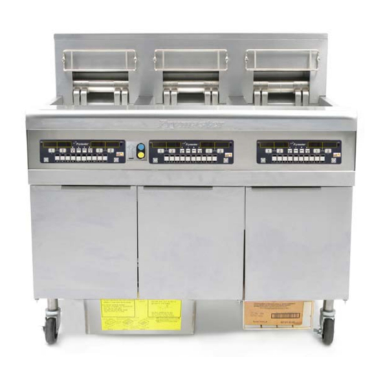
FRYMASTER BIELA14 SERIES GEN II
LOV™ ELECTRIC FRYER
Frymaster L.L.C., 8700 Line Avenue, Shreveport, LA 71106
PHONE 318-865-1711
SERVICE HOTLINE
1-800-24-FRYER
email:
service@frymaster.com
FOR YOUR SAFETY
Do Not Store or use gasoline or other
flammable vapors and liquids in the
vicinity of this or any other appliance.
FAX 318-219-7135
*8196446*
MAY 2011
Advertisement
Table of Contents
Troubleshooting

Related Manuals for Frymaster LOV BIELA14


Summary of Contents for Frymaster LOV BIELA14
- Page 1 8700 Line Avenue SHREVEPORT, LOUISIANA 71106 PHONE: 1-318-865-1711 TOLL FREE: 1-800-551-8633 1-800-24 FRYER FAX: 1-318-688-2200 Frymaster L.L.C., 8700 Line Avenue, Shreveport, LA 71106 PRINTED IN THE UNITED STATES www.frymaster.com SERVICE AND PARTS MANUAL LOV™ ELECTRIC FRYER PHONE 318-865-1711 FAX 318-219-7135...
- Page 2 RECEIVED FROM AN UNAUTHORIZED SERVICE CENTER. This appliance is intended for professional use only and is to be operated by qualified personnel only. A Frymaster Dean Authorized Service Agency (ASA) or other qualified professional should perform installation, maintenance, and repairs.
- Page 3 Adequate means must be provided to limit the movement of this appliance without depending on or transmitting stress to the electrical conduit. A restraint kit is provided with the fryer. If the restraint kit is missing contact your local Frymaster Authorized Service Agency (ASA) for part number 826-0900.
- Page 4 3. If any parts, except fuses and filter O-rings, become defective during the first two years after installation date, Frymaster will also pay straight-time labor costs up to two hours to replace the part, plus up to 100 miles/160 km of travel (50 miles/80 km each way).
-
Page 5: Electrical Power Specifications
• no fryer will be warranted under the ten-year program for which a proper start-up form has not been received. This warranty also does not cover: • transportation or travel over 100 miles/160 km (50 miles/80 km each way), or travel over two hours;... -
Page 6: Table Of Contents
BIELA14 SERIES GEN II LOV™ ELECTRIC FRYERS CAUTIONARY STATEMENTS ... i WARRANTY STATEMENT ... ii ELECTRICAL POWER SPECIFICATIONS ... iii CHAPTER 1: Service Procedures General ...1-1 Replacing a Computer ...1-1 Replacing Component Box Components ...1-1 Replacing a High-Limit Thermostat ...1-3 Replacing a Temperature Probe ...1-3 Replacing a Heating Element ...1-5 Replacing Contactor Box Components ...1-7... - Page 7 BIELA14 SERIES GEN II LOV™ ELECTRIC FRYERS TABLE OF CONTENTS cont. 1.19.3 Component Wiring CSA ... 1-46 1.19.4 Component Wiring Australia ... 1-47 1.19.5 Contactor Box-Delta Configuration ... 1-48 1.19.6 Contactor Box-WYE Configuration ... 1-49 1.19.7 Simplified Full-Vat Delta Wiring ... 1-50 1.19.8 Simplified Dual-Vat Delta Wiring ...
-
Page 8: Chapter 1: Service Procedures
BIELA14 SERIES GEN II LOV™ ELECTRIC FRYERS CHAPTER 1: SERVICE PROCEDURES 1.1 General Before performing any maintenance on your Frymaster fryer, disconnect the fryer from the electrical power supply. To ensure the safe and efficient operation of the fryer and hood, the electrical plug for the 120-volt line, which powers the hood, must be fully engaged and locked in its pin and sleeve socket. - Page 9 7. Reconnect the wiring disconnected in step 5, referring to your notes and the wiring diagrams on the fryer door to ensure that the connections are properly made. Also, verify that no other wiring was disconnected accidentally during the replacement process.
-
Page 10: Replacing A High-Limit Thermostat
7. Insert the leads into the 12-pin connector C-6 (see illustration below). For full-vat units or the left half of a dual-vat unit (as viewed from the rear of the fryer) the leads go into positions 1 and 2 of the connector. - Page 11 9. Insert the temperature probe leads into the 12-pin connector C-6 (see illustration below). For full- vat units or the right half of a dual-vat unit (as viewed from the rear of the fryer) the red (or yellow) lead goes into position 3 and the white lead into position 4 of the connector. For the left half of a dual-vat unit (as viewed from the rear of the fryer), the red (or yellow) lead goes into position 9 and the white lead into position 10.
-
Page 12: Replacing A Heating Element
Using a pin pusher, disconnect the probe wires from the 12-pin connector. 3. In the rear of the fryer disconnect the 6-pin connector for the left element (as viewed from the front of the fryer) or the 9-pin connector for the right element from the contactor box. - Page 13 Full vat element wire routing Pull the element wires through the bushings on either side of the frypot and down the back. Element wires should be routed to the right of the ATO temperature probe on the back wall of the frypot. Dual vat element wire routing Pull the element wires through the bushings on either side of the frypot...
-
Page 14: Replacing Contactor Box Components
3. Remove the two screws securing the cover of the contactor box. The contactor boxes above the filter pan are accessed by sliding under the fryer. They are located to the left and right above the guide rails (see photo below). The contactor boxes for frypots not over the filter pan are accessed by opening the fryer door directly under the affected frypot. -
Page 15: Replacing A Frypot
2. Remove lower back panel. 3. Remove filter pan, lid and downspout splash shield. 4. Remove clevis clip from dispose handle at rear of fryer and let handle drop out of waste valve bracket. 5. Remove two screws holding waste valve handle at front of fryer and remove bracket and handle from fryer. - Page 16 5. Unplug the wiring harnesses and ground wires from the backs of the computers. Remove the computers by lifting them from the hinge slots in the control panel frame. 6. Remove the tilt housing and back panels from the fryer. The tilt housing must be removed first in order to remove the upper back panel.
-
Page 17: Built-In Filtration System Service Procedures
30. Reinstall computers in the control panel frame and reconnect the wiring harnesses and ground wires. 31. Reposition the fryer under the exhaust hood and reconnect it to the electrical power supply. 1.9 Built-in Filtration System Service Procedures 1.9.1 Filtration System Problem Resolution One of the most common causes of filtration problems is placing the filter pad/paper on the bottom of the filter pan rather than over the filter screen. -
Page 18: Replacing The Filter Motor, Filter Pump And Related Components
2. Disconnect the fryer from the electrical power supply and reposition it to gain access to both the front and rear. 3. Disconnect the flexline running to the oil-return manifold at the rear of the fryer as well as the pump suction flexline at the end of the filter pan connection (see photo on the following page). - Page 19 When replacing a filter relay in the left component box, ensure the 24VDC relay (8074482) is used. Similar Frymaster fryers use a 24VAC relay, which can lead to confusion. The 24VDC is used in the LOV™ fryer. Disconnect flexlines indicated by the arrows.
-
Page 20: Ato (Automatic Top-Off) Service Procedures
1.10 ATO (Automatic Top-off) Service Procedures The automatic top-off system is activated when the oil level falls below a sensor in the rear of the frypot. The signal is sent to the ATO board to engage the return actuator to the frypot and turn on the ATO pump. The pump draws oil from the JIB (Jug In Box) through the rear return manifold into the rear of the frypot. - Page 21 BOARD Probable Causes 1-14 Corrective Action Ensure JIB has oil. Check to see that fryer is heating. Fryer temperature must be at setpoint. Check probe resistance. If probe is bad, replace the probe. Ensure that the oil in the JIB is above 70°F (21°C).
- Page 22 1.10.2 ATO (Automatic Top-Off) Board Pin Positions and Harnesses Connector From/To RTI Add Solenoid ATO Pump Relay JIB Reset Switch RTI Add Solenoid ATO Pump Relay JIB Reset Switch Transformer J4 (Rear) / J5 (Front) ATO 4 & 5 Battery Jumper J3 - Vat #3 J2 - Vat #2...
-
Page 23: Replacing The Ato Board, Lon Gateway, Ato Pump Relay Or Transformer
1.10.3 Replacing the ATO board, LON Gateway, ATO pump relay or Transformers Disconnect the fryer from the electrical power supply. Locate the ATO box (see Figure 1 on page 12), behind the JIB (Jug In Box). Remove the cover to expose the transformers, relay and LON gateway (if installed) (see Figure 2). - Page 24 Buttons and LED’s Manual – This button is used to toggle between auto and manual filtration mode. A corresponding LED is lit when in Manual mode. When pressed, a message will be sent to all vats, indicating the mode has changed. The following buttons are inoperable in auto mode: Select - This button is used to scroll through available vats, choosing one to be manually filtered.
-
Page 25: Mib Display Diagnostics
An AIF board issue. Locator pin issue. Corrective Action Ensure filter pan is fully inserted into fryer. If the MIB board displays a “P” the pan is not fully engaged into the pan switch. Ensure the oil level is above the top oil level sensor. - Page 26 Problem Probable Causes MIB board alternating Network error on the CAN bus “E” and “vat number communication. and side”. Corrective Action Ensure the CAN bus system is terminated at BOTH ENDS (on the M3000 connector J6 and on the ATO board connector J10) with a resistor equipped 6-pin connector.
- Page 27 Transformer Filter Relay Blue LED RTI Open Switch RTI Closed Switch Pan Switch RTI Open Switch RTI Closed Switch To RTI connection in rear of fryer Harness # Pin # Function Ground CAN Lo CAN Hi 8074546 Ground CAN Lo...
- Page 28 1.11.4 MIB (Manual Interface Board) Display Diagnostics DISPLAY Drain Vat # (The vat number is followed by an “L” to indicate left side of a split vat or an “r” to indicate the right side of a split vat or a full vat.) Vat # (The vat number is followed by an “L”...
-
Page 29: Replacing The Mib Board
1.11.6 Replacing the MIB Board Disconnect the fryer from the electrical power supply. Remove the torx screws from the MIB cover, exposing the MIB board (see Figure 11). Removing the screw at top center lets the MIB board hinge down. Carefully remove the plugs on the rear of the board (see Figure 12). -
Page 30: Rti Service Issues
RTI Service Issues 1.12.1 RTI MIB Tests The LOV™ fryer will ONLY operate with RTI systems that have the new RTI updated three-pole float switch. If the float switch is the older two-pole switch, call RTI. These float switches are polarity specific which may short to ground and damage an MIB board. -
Page 31: Rti Lov Wiring
1.12.2 RTI LOV™ Wiring 1.12.3 Frymaster LOV™ Fryer and RTI Bulk Oil System Plumbing Schematic 1-24... -
Page 32: Rti Lov Quick Reference
16. Press “ ” if the filter pan is empty. Select “ ” if pan still has oil in it. 17. “Close Dispose Valve” is displayed. 18. Close the dispose valve ensuring the handle is pushed completely towards the fryer. 19. “Insert Pan” is displayed. - Page 33 RTI relay stuck If using two fryer systems that are both attached to the RTI system, they may not be able to fill both units at the same time if they have an RTI unit with a single head. Some RTI units have dual heads which can fill simultaneously.
-
Page 34: Aif (Automatic Intermittent Filtration) Service Procedures
(gray/white wire). Closed should read 0-560Ω. Open should read 3.8K Ω – 6.6K Ω. If proper voltages are present at the connector actuator operate, reset power to the fryer. If it still doesn’t operate replace actuator. Ensure the actuator is plugged into... - Page 35 1.13.2 AIF (Auto Intermittent Filtration) Actuator Board Pin Positions and Harnesses Connector From/To FV Return Actuator FV AIF RTD DV AIF RTD Oil Level Sensor (Gas) Locator Pin Locator DV Return Actuator MIB J2 or AIF J5 AIF J4 or ATO J10 FV Drain Actuator...
-
Page 36: Replacing An Aif Board
1.13.3 Replacing an AIF (Automatic Intermittent Filtration) board Disconnect the fryer from the electrical power supply. Locate the AIF board to be replaced under a frypot. Mark and unplug the harnesses. The AIF board assembly is held in place with one screw in the front of the assembly (see Figure 14). -
Page 37: M3000 Computer Service Procedures
1.13.5 Replacing a Rotary Actuator Disconnect the fryer from the electrical power supply. Locate the actuator to be replaced and mark and unplug the actuator. The actuators are held in place by two allen screws. Loosen the allen screws. It may be necessary to remove a gas line to the burner when removing a drain actuator. - Page 38 24 hour filter pad change prompt CHANGE FILTER has occurred or change filter pad was PAD. ignored on a prior prompt. A. Filter pan is not fully inserted into fryer. M3000 display shows B. Missing filter pan magnet. INSERT pan. C. Defective filter pan switch.
- Page 39 Reset the setpoint of the vat before trying to cook product. Turn off the vat with the issue. The error is displayed if the fryer loses its ability to heat oil. It is also displayed when the oil temperature is above 450°F (232°C) and the...
- Page 40 To enter level one, level two passwords: Press and hold the TEMP and INFO buttons simultaneously until level 1 or level 2 is displayed. Release the buttons and ENTER Code appears. • 1234 – Fryer Setup, Level One and Level Two • 4321 – Usage Password (resets usage statistics).
-
Page 41: Service Required Errors
ATO RTD reading out of range TEMP Probe reading out of range Internal MIB software error SD card removed during update Energy type in fryer setup is incorrect. (ie. Set proper energy type gas or electric) Press 1234 to enter setup to properly configure fryer. -
Page 42: Error Log Codes
1.14.4 Error Log Codes Refer to page 1-39, level 2 program for access to the E-log. The ten most recent errors are listed from A-J, with A being the most recent error. Code ERROR MESSAGE REMOVE DISCARD (Right) REMOVE DISCARD (Left) ERROR TEMP PROBE FAILURE HI 2 BAD HOT HI 1... -
Page 43: Tech Mode
1.14.5 Tech Mode Tech mode allows technicians to reset all passwords set in levels one and two and change when the fryer calls for a filter pad change. The default is 25 hours. 1. Press and hold MODE is displayed. -
Page 44: M3000 Filter Error Flowchart
30 seconds. If the computer displays SERVICE REQUIRED, the fryer can be used in most cases by answering NO when the prompt FIXED? YES NO is displayed. The message repeats every 15 minutes until the issue is repaired and error cleared by a technician. -
Page 45: M3000 Menu Summary Tree
1.14.7 M3000 Menu Summary Tree Reflected below are the major programming sections in the M3000 and the order in which submenu headings will be found under the sections in the Installation and Operation Manual. Adding New Menu Items Storing Menu Items in Product Buttons Draining, Refilling, and Disposing of Oil See section 4.10.2 See section 4.10.3... -
Page 46: M3000 Board Pin Positions And Harnesses
1.14.8 M3000 Board Pin Positions and Harnesses Connector From/To SD Card Interface Board to Computer Interface Board Ground to Computer Next M3000 J7 or Network Resistor MIB J1 or previous M3000 J6 Harness PN 12VAC In Ground 12VAC In FV Heat Demand V Relay DV Heat Demand R/H B/L... -
Page 47: Loading And Updating Software Procedures
26. SKIM VAT is displayed changing to CONFIRM. 27. Press the (1 ) button. The auto filter cycle should start. 28. Once the filter cycle is complete, repeat on each vat in the fryer. 29. Once all vats have been successfully filtered the software update is finished. -
Page 48: Data Network Flowchart
1.16 BIELA14 Series LOV™ Data Network Flowchart 1-41... -
Page 49: Interface Board Diagnostic Chart
1.17 Interface Board Diagnostic Chart The following diagram and charts provide ten quick system checks that can be performed using only a multimeter. PN 826-2260 (106-6664) NOTE – Pin 1 is located in the bottom right corner of Both J1 and J2. These test points are ONLY for LOV™ Series boards with J1 and J2 plugs on the front of the board. -
Page 50: Probe Resistance Chart
1.18 Probe Resistance Chart Probe Resistance Chart For use with fryers manufactured with Minco Thermistor probes only. OHMS OHMS 1059 1204 1070 1216 1080 1226 1091 1237 1101 1247 1112 1258 1122 1268 1133 1278 1143 1289 1154 1299 1164 1309 1174 1320... -
Page 51: Wiring Diagrams
1.19 Wiring Diagrams 1.19.1 Component Wiring (Domestic) 1-44... -
Page 52: Component Wiring Ce
1.19.2 Component Wiring (CE) 1-45... -
Page 53: Component Wiring Csa
1.19.3 Component Wiring (CSA) 1-46... -
Page 54: Component Wiring Australia
1.19.4 Component Wiring (Australia) 1-47... -
Page 55: Contactor Box-Delta Configuration
1.19.5 Contactor Box – Delta Configuration 1-48... -
Page 56: Contactor Box-Wye Configuration
1.19.6 Contactor Box – WYE Configuration 1-49... - Page 57 1.19.7 Simplified BIELA14 LOV™ Gen II Series – Full Vat Delta Wiring 1-50...
- Page 58 1.19.8 Simplified BIELA14 LOV™ Gen II Series – Dual Vat Delta Wiring 1-51...
- Page 59 1.19.9 Simplified BIELA14 LOV™ Gen II Series – Full Vat Wiring EXPORT WYE 1-52...
- Page 60 1.19.10 Simplified BIELA14 LOV™ Gen II Series – Dual Vat Wiring EXPORT WYE 1-53...
- Page 61 1.19.11 BIELA14 Gen II Series LOV™ Simplified Wiring 1-54...
-
Page 62: Chapter 2: Parts List
BIELA14 SERIES GEN II LOV™ ELECTRIC FRYERS CHAPTER 2: PARTS LIST 2.1 Accessories ITEM PART # 809-0171 Thumbscrew, ¼ -20 X 1⅜-inch Universal Hood 809-0402 Thumbscrew, ¼ -20 X ½-inch Cap-N-Splash Hood 810-2793 Hanger, Wireform Basket 809-0921 Spacer, Basket Hanger 803-0398 Brush, Frypot 823-7263... -
Page 63: Doors, Sides, Tilt Housings, Cap N Splash, Top Caps And Casters
823-6421 Three Station 823-6422 Four Station 823-6887 Five Station Top Cap (Top cap for five station fryer shown) 106-7835 Two Station (Also requires four 809-0078 10-32 Nutserts) 106-5979 Three Station (Also requires six 809-0078 10-32 Nutserts) 106-7576 Four Station (Also requires eight 809-0078 10-32 Nutserts) -
Page 64: Drain System Components
Drain System Components 2.3.1 Drain Tube Sections and Associated Parts See Section 2.3.2 for Drain Valves ITEM PART# 823-6020 Drain Tube, Full-Vat Left Closed/Right End Open 823-6112 Drain Tube, Dual-Vat Left Closed/Right End Open 108-1874 Drain Tube, Dump (Use 108-1882 for French Unit) 108-1876 Drain Tube, Full-Vat 2 Bat. -
Page 65: Drain Valves And Associated Parts
2.3.2 Drain Valves and Associated Parts 2.3.2.1 Linear Actuator Drain Valves ITEM PART # 809-0540 Nut, ½-13 2-Way Hex Lock 900-2936 Retainer, Nut Drain Valve 232-5701 Handle, Drain Valve FV or DV Right 231-5701 Handle, Drain Valve DV Left 824-2048 Mount, Electric Drain Actuator Right 824-2047 Mount, Electric Drain Actuator Left... -
Page 66: Component Boxes
Electronics and Wiring Components 2.4.1 Component Boxes... - Page 67 2.4.1 Component Boxes cont. ITEM PART # 106-5592 Box Assembly, Component 200-3300 Bracket, Component Box Strain Relief 806-9495SP Terminal Block √ 4 807-4346 Relay, 120V DPDT 20A √ 5 807-4482 Relay, Filter 2 Pole 30A DPDT 24VDC 807-0037 Terminal, ¼-inch Push-on 807-0121 Bushing, Heyco Plastic AB-625-500 807-0922...
-
Page 68: Contactor Boxes
2.4.2 Contactor Boxes 2.4.2.1 Left and Right Contactor Box Configurations LEFT HAND BOX COVER STANDARD MECHANICAL LEFT AND RIGHT CONFIGURATIONS 120/440/480v LEFT AND RIGHT STANDARD AND MECHANICAL CONFIGURATIONS CANADIAN 14kW RIGHT CONFIGURATIONS RIGHT HAND BOX COVER... - Page 69 2.4.2.1 Left and Right Contactor Box Configurations cont. NOTES: Left and right contactor box assemblies are mirror images of one another. With the exception of the box itself, all components of a left-hand assembly are the same as those in the corresponding right-hand assembly and vice versa except for the hood relay which occurs in the right or large box only.
-
Page 70: Heating Element Assemblies And Associated Parts
2.4.3 Heating Element Assemblies and Associated Parts 2.4.3.1 Element Assemblies and Hardware NOTE: These elements apply only to BIELA14 Gen II Series Fryers. - Page 71 2.4.3.1 Element Assemblies and Hardware cont. ITEM PART # Element 826-2198 200V 7.0 kW (220V 8.5kW used in some export 3-phase 4-wire WYE units) √ 826-2192 208V 17.0 kW 826-2200 220V 17.0 kW (240V 8.5kW used in some export 3-phase 4-wire WYE units) 826-2193 230V 17.0 kW...
-
Page 72: Element Tube Assemblies
2.4.3.2 Element Tube Assemblies FULL-VAT ELEMENT ASSEMBLY DUAL-VAT ELEMENT ASSEMBLY 2-11... -
Page 73: Computers
2.4.3.2 Element Tube Assemblies contd. ITEM PART # 108-0297SP Tube Assembly RE Element, Full-Vat 108-0298SP Tube Assembly RE Element, Dual-Vat 810-3246 Bushing and Tube Assembly, Dual-Vat 108-0315 Bracket Assembly, LH Element Tube Support 108-0316 Bracket Assembly, RH Element Tube Support 220-0122 Plate, Element Tube Support Inner 220-0123... -
Page 74: Wiring
2.4.5 Wiring 2.4.5.1 Contactor Box Wiring Assemblies – 12-Pin Dual-Vat C-1 ITEM PART # 106-5980SP Contactor Box Harness Assembly Dual Vat Standard (See wiring diagrams on pages 1-41 thru 1-43.) 2.4.5.2 Contactor Box Wiring Assemblies – 12-Pin Full-Vat C-1 ITEM PART # 106-6031SP Contactor Box Harness Assembly Full Vat Standard (See wiring diagrams on pages 1-41 thru 1-43.) -
Page 75: Contactor Box Wiring Assemblies 6-Pin Left Element
2.4.5.3 Contactor Box Wiring Assembly – 6-Pin (Left Element) ITEM PART # 106-8744 14/17 kW Mechanical Contactor 2.4.5.4 Contactor Box Wiring Assembly – 9-Pin (Right Element) ITEM PART # 106-8745 14/17 kW Mechanical Contactor COMPONENT COMPONENT 2-14... -
Page 76: Main Wiring Harnesses
2.4.5.5 Main Wiring Harnesses 2-15... -
Page 77: Component Box And Filter Pump Wiring Harnesses
2.4.5.6 Component Box and Filter Pump Wiring Harnesses ITEM PART # 106-5750SP Full Vat Control Harness J4 to J2 (Standard) 106-5751SP Dual Vat Control Harness J4 to J1 and J2 (Standard) 108-0490 Filter Pump C2 to Component Box Wiring Harness 2.4.5.7 Interface Board to Controller Wiring Harness –... -
Page 78: M3000, Mib, Aif And Ato Wiring Harnesses
2.4.5.8 M3000, MIB, AIF and ATO Wiring Harnesses ITEM PART # 807-4546 Computer Communication (used from Computer to Computer) 807-4547 AIF Communication/Power (used from MIB to AIF and AIF to AIF) MIB Power/Blue LED/Pan Sw (used from Transformer and Fltr Rly to 807-4649 MIB to Blue LED and Pan Sw) 807-4655... -
Page 79: Filtration System Components
Filtration System Components 2.5.1 Filtration Components 2-18... - Page 80 Crumb Tray, Two-Vat Fryer, Half Size Filter Pan 810-3268 Hold-Down Ring for Pad 16.56 x 22.32, Standard Size Pan 3, 4, and 5 Vat 810-3289 Hold-Down Ring for Pad 11.20 x 19.10, Two-Vat Fryer, Half Size Filter Pan 200-2240 SanaGrid Filter Screen, Standard Size Filter Pan 220-2901...
-
Page 81: Auto Intermittent Filtration Components
2.5.2 Auto Intermittent Filtration Components 2.5.2.1 LOV™ Indicator Lights Assembly ITEM PART # 106-8106SP Light, Blue 24VDC LED Flush 106-8105SP Light, Yellow/Orange 24VDC LED Flush 230-4271 Plate, Control Frame LOV™ 2.5.2.2 Manual Interface Board Assembly ITEM PART # 108-1298 Assembly, MIB 220-6288 Cover, MIB 108-2156... -
Page 82: Lov Pcb Board Matrix
2.5.2.3 AIF Board Assembly ITEM PART # 108-1305 Assembly, AIF 824-1988 Cover, AIF Board 816-0814 Gasket, AIF Board 816-0815 Gasket, Computer Board 108-1304 Board, AIF √ 816-0820 Seal, AIF Board 108-0097 Panel Assembly, AIF Box √ Recommended parts. 2.5.2.4 LOV PCB/Computer Board Matrix PART # 108-2156 Assembly, MIB PCB w/ metal work... - Page 83 Frypot Assemblies and Associated Parts 2.6.1 Frypots with Linear Actuators See Page 2-5 for Drain Valve Assemblies. ITEM PART # 823-7436 Frypot, Full-Vat LOV™ 823-7437 Frypot, Dual-Vat LOV™ Thermostat Assembly, High-Limit Long Standard √ 826-2454 Non-CE Full Vat 425°F (218°C) (17kW FV and 14kW FV) (Color Coded Black 806-7543) 826-2456 Non-CE Dual Vat 435°F (224°C) (22kW, 17kW DV and 14 kW DV)
- Page 84 2.6.2 Frypots with Rotary Actuators ITEM PART # 823-7672 Frypot, Full-Vat LOV™ 823-7673 Frypot, Dual-Vat LOV™ (use 823-7745 for Hybrid Fish Vat) Thermostat Assembly, High-Limit Long Standard √ 826-2454 Non-CE Full Vat 425°F (218°C) (17kW FV and 14kW FV) (Color Coded Black 806-7543) 826-2456 Non-CE Dual Vat 435°F (224°C) (22kW, 17kW DV and 14 kW DV)
-
Page 85: Oil Return Manifolds
2.7 Oil Return Manifolds ITEM PART # 810-3015 Manifold, Two-Station Fryer 810-3016 Manifold, Three-Station Fryer 810-3017 Manifold, Four-Station Fryer 810-3018 Manifold, Five-Station Fryer 813-0907 Cap, 15/16-inch Valve * Not illustrated. 2.8 Return Valves and Associated Parts 2.8.1 Return Valves and Associated Parts (Linear Actuators) -
Page 86: Auto Top Off Components
2.8.1 Return Valves and Associated Parts (Linear Actuators) cont. ITEM PART # 232-5702 Handle, Return Valve with Locator FV or DV Right 231-5702 Handle, Return Valve with Locator DV Left 900-2935 Retainer, Nut Oil Return Valve 810-2201 Valve, ½-inch Ball 823-7233 Mount, Return Actuator Right 823-7232... -
Page 87: Automatic Top Off Board Assembly
2.9.2 JIB Cap and Pick Up Assembly cont. ITEM PART # 823-7738 Inlet, Oil Reservoir Tube 816-0870 Clamp 2.9.3 Automatic Top Off Board Assembly 108-0506SP 120V Assy ITEM PART # 108-0653 Box, Assembly Auto Top Off Board 220-5679 Cover, Top Off Board Box 108-1279 PCB Board, Automatic Top Off √... -
Page 88: Ato Pump Assembly
Elbow, ½” BM 45° 810-1668 Adaptor, Male ⅝” OD x ½” 812-2083 Hose LOV Fryer JIB (Cut and attach to item 7 with a ty wrap) 811-1166 Hose, Silicone Braided 18” (sold by the foot) * Not illustrated. √ Recommended parts. -
Page 89: Ato Pump Assembly Service Kit (Larger Top Off Lines)
2.9.5 ATO Pump Assembly Service Kit (Larger Top Off Lines) JIB hose connects here. ITEM PART # 108-3041 Kit, Pump BIELA Topoff Service Kit √ 108-0639 810-3265 810-3591 810-0667 810-1069 810-3666 816-0782 813-0940 813-0062 813-0087 823-8063 813-0165 813-0247 108-2054 810-1668 813-0907 * Not illustrated. -
Page 90: Rti
2.10 2.10.1 RTI Manifold and Accessories TO DRAIN DOWNSPOUT TO TOP OFF TO OIL PUMP INTAKE RETURN AND TO FILL MANIFOLD RTI JIB TO RTI BYPASS CHECK VALVE AND TO DRAIN DOWNSPOUT WASTE OIL TO RTI DISPOSE TANK 2-29 FRESH OIL FROM RTI TANK TO OIL RETURN... - Page 91 2.10.1 RTI Manifold and Accessories cont. ITEM PART # √ 106-6830 Solenoid Assembly 108-0446 Valve, RTI Waste Assembly (see page 2-32 for parts) 810-1668 Adaptor, Male ⅝” OD x ½” 220-5658 Cover, RTI Dust Plug 807-4760 Harness, RTI – MIB connection 810-1057 Flexline, ⅝”...
-
Page 92: Rti Dispose Waste Valve
2.10.2 RTI Dispose Waste Valve ITEM PART # 108-0446 Valve, RTI Dispose Waste 108-0445 Bracket, RTI Waste Valve 220-5615 Handle, RTI Waste Valve 807-4936 Microswitch, Gold Sealed 810-0278 Valve, ½” Ball 900-2935 Retainer, Nut Return Valve 901-2348 Cover, DV Safety Switch 902-2348 Cover, DV Safety Switch 2.10.3 RTI Test Box... -
Page 93: Wiring Connectors, Pin Terminals And Power Cords
2.11 Wiring Connectors, Pin Terminals and Power Cords ITEM PART # Power Cords 807-0154 100/120V–15A 3-wire, w/grounded plug 807-4317 100/208/240V-16A 3-Wire with Plug LOV CE 807-1685 100/208/240V–18A 3-wire, w/o plug 807-4316 120V 5-wire, w/grounded plug LOV 807-3817 208/240V 3-Phase 4-wire w/grounded plug 807-5105 208/240V 3-Phase 4-wire w/grounded plug 105”... -
Page 94: Fasteners
2.12 Fasteners ITEM PART # 809-0429 Bolt, ¼-inch – 20 x 2.00-inch Hex Head ZP Tap 809-0131 Bolt, ¼-inch -20 x ¾-inch Hex 809-1020 Cap Screw, 5/16-inch-18 5.50” NC Hex (Connects pump to motor.) 809-0448 Clip, Tinnerman 826-1366 Nut, 4-40 Keps Hex (Pkg. of 25) (809-0237) 826-1358 Nut, 6-32 Keps Hex (Pkg. - Page 95 THIS PAGE INTENTIONALLY LEFT BLANK...
- Page 96 Frymaster, L.L.C., 8700 Line Avenue, Shreveport, Louisiana 71106 TEL 1-318-865-1711 FAX (Parts) 1-318-219-7140 (Tech Support) 1-318-219-7135 819-6446 SERVICE HOTLINE MAY 2011 PRINTED IN THE UNITED STATES 1-800-551-8633...