Table of Contents
Advertisement
Advertisement
Table of Contents

Related Manuals for Planet FGSW-2402S


Summary of Contents for Planet FGSW-2402S
-
Page 2: Fcc Warning
PLANET is a registered trademark of PLANET Technology Corp. All other trademarks belong to their respective owners. Disclaimer PLANET Technology does not warrant that the hardware will work properly in all environments and applications, and makes no warranty and representation, either implied or expressed, with respect to the quality, performance, merchantability, or fitness for a particular purpose. -
Page 3: Ce Mark Warning
This is a Class A product. In a domestic environment, this product may cause radio interference, in which case the user may be required to take adequate measures. Revision PLANET Switch User's Manual FOR MODELS: FGSW-2402S Part No.: EM-FG24V1 FGSW-2402S User's Manual... -
Page 4: Table Of Contents
TABLE OF CONTENTS 1. INTRODUCTION..............1 1.1 C ............... 1 HECKLIST 1.2 A ............1 BOUT THE WITCH 1.3 F ................ 2 EATURES 1.4 S ............... 3 PECIFICATIONS 2. HARDWARE DESCRIPTION..........7 2.1 F ..............7 RONT ANEL 2.1.1 LED indictor for whole switch ........8 2.1.2 LED indictor for 10/100Base-TX port ....... - Page 5 5. TROUBLESHOOTING............29 APPENDIX A................31 ’ A.1 S RJ-45 P ....... 31 WITCH SSIGNMENTS A.2 10/100M , 10/100B -TX ........31 A.3 RJ-45 ........32 CABLE PIN ASSIGNMENT FGSW-2402S User's Manual...
- Page 6 This page intentionally left blank! PLANET Switch series...
-
Page 7: Introduction
1.2 About the Switch With two open slots available for fiber or copper Gigabit modules, the FGSW-2402S can accelerate your Cat5 backbone to 10 times the performance of existing 100 Megabit without re-wiring your cabling infrastructure. The optional Gigabit modules can be Gigabit fiber-optic, (SX or LX) and also Fast Ethernet fiber-optic up to 10 kilometers away. -
Page 8: Features
9 levels of upstream/downstream restriction. This, couple with the flexible 100FX, 1000SX/LX/T module options make the FGSW-2402S one of the best and most cost-effective MTU switch solutions for Multi-tenant service providers. 1.3 Features w Complies with the IEEE802.3, IEEE802.3u, IEEE802.3z and... -
Page 9: Specifications
Dimensions 430 x 200 x 44 mm 1U height Weight 2.8 kg (5.5 lb) Power Requirement 100~240 (±10%) VAC, 50-60 (±3) Hz Power Consumption / 40 Watts maximum / 136 BTU/hr maximum Dissipation Maximum Current 0.15A/0.10A (@110/240VAC) FGSW-2402S User's Manual... - Page 10 Switch Processing Store-and-forward Scheme Address Table 8K entries, auto learning/ageing Queue Buffer 6Mbit shared buffer Flow Control Back pressure for half duplex, IEEE 802.3x for full duplex Packet Control Runt & CRC filtering, Broadcast storm control Power, Ready LED indicators LNK/ACT, 100, FDX/COL for each port 1000,100,10(FX), FDX/COL, TX, RX for modules Switch Management...
- Page 11 CSA/NRTL (C.22.2.950, UL1950), TÜV/GS (EN60950) Immunity EN60555-2 Class A, EN60555-3 Temperature Standard Operating: 0~50ºC (32~122ºF) Storage -40~70ºC (-40~158ºF) Humidity 5% to 95% (Non-condensing) Standards IEEE 802.3 (Ethernet), IEEE 802.3u (Fast Ethernet), IEEE 802.3ab, IEEE802.3z (Gigabit Ethernet), IEEE8023x (flow control) FGSW-2402S User's Manual...
- Page 12 This page intentionally left blank! PLANET Switch series...
-
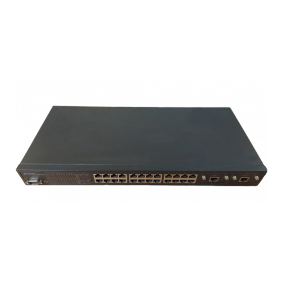
Page 13: Hardware Description
It includes a power and port indicator for each port and a RS-232 console port for setting up the switch via a connection to a console terminal or PC using a terminal emulation program. Figure 1:FGSW-2402S Switch front panel Figure 2: Detail view of LED panel FGSW-2402S User's Manual... -
Page 14: Led Indictor For Whole Switch
Blink: Half-Duplex/ Collision Yellow Off: Half-duplex or not connected 2.1.3 LED indictor for modules There indicators modules FGSW-2402S. These modules have different LED definition when different module installed. SGSW-A1GT 10/100/1000Base-T modules 1000 Green Lit: indicate link status and connected on 1000Mbps... -
Page 15: Reset Button
The rear panel of the Switch indicates an AC inlet power socket, which accepts input power from 100 to 240VAC, 50-60Hz. Figure 3:FGSW-2402S Switch rear panel Power Notice: 1. The device is a power-required device, it means, it will not operate till it is powered. -
Page 16: Hardware Installation
Step1: Attach the rubber feet to the recessed areas on the bottom of the switch. Step2: Place the FGSW-2402S on a desktop or shelf near an AC power source. Step3: Keep enough ventilation space between the switch and... - Page 17 To install the switch in a 19-inch standard rack, follow the instructions described below. Step1: Place your FGSW-2402S on a hard flat surface, with the front panel positioned towards your front side. Step2: Attach a rack-mount bracket to each side of the switch with supplied screws attached to the package.
-
Page 18: Network Installation
Figure 5: Mounting the Switch in a Rack Step6: Proceed with the steps 4 and steps 5 of session 2.3.1.1 Desktop or Shelf Mounting to connect the network cabling and supply power to your switch. 2.3.2 Network Installation 2.3.2.1 Connecting end node, hub or switch 1.Place the Switch on a smooth surface or fasten the mounting brackets with the provided screws in a standard 19 ”... - Page 19 To reliably operate your network at 100Mbps and 1000Mbps, you must use an Unshielded Twisted-Pair (UTP) Category 5 cable, or better Data Grade cabling. While a Category 3 or 4 cable may initially seem to work, it will soon cause data loss. FGSW-2402S User's Manual...
-
Page 20: Connect To
Function: the indicator LED flash up whenever there is a collision between a directly attached end node and any other node, and light up steadily for Full-duplex mode. FGSW-2402S 100 meters max. Fiber 10km 100 meters max. -
Page 21: Configuration
Prepare a RS-232 serial cable. Attach the 9-pin female connector to the male connector on the switch. Plug the other side of this cable to your PC. Hyper Terminal In Windows 95/98/2000/XP,launch “HyperTerminal”, create a new connection, and adjust settings as below: FGSW-2402S User's Manual... -
Page 22: Main Menu
3.2 Main Menu Launch the new terminal you just set up, and then, turn on the switch. See the following messages for successful connection. Password : The default password is “admin”. After type the password, you can see the screen as below: To enter any of the sub-menus, simply type the number on the main menu PLANET Switch series... -
Page 23: Submenu: (1) Device Configuration
One Uplink (MTU): port 1-25 will be assign to different VLAN groups and uplink to port 26. Two Uplink (MDU): it will assign port 1-12 as different VLAN groups and uplink to port 25, assign port 13-24 as different groups and uplink to port 26 FGSW-2402S User's Manual... -
Page 24: Submenu :(2) Port Configuration
3.4 Submenu :(2) Port Configuration Entry: Select “2” from Main Menu. Purpose: Media Speed Control on each port. Default: All ports assigned to one VLAN. Type ’’N’’ to next page. Type “port number” to enter the port configuration of each port. The following screen is shown as below: PLANET Switch series... -
Page 25: Submenu: (3) Port Statistics
Bytes Rx: Octets count on received good unicast frames of priority level 1. Broadcast Rx: Frame count on received good broadcast frames of all priority. Multicast Rx: Frame count on received good multicast frames of all priority levels. FGSW-2402S User's Manual... - Page 26 Frames Sent: Frame count on successfully transmitted unicast frames. Bytes Sent: Octets count on transmitted unicast frames of priority level 1. Tx Broadcast: Frame count on successfully transmitted broadcast frames. Tx Multicast: Frame count on successfully transmitted multicast frames. In Dropped: Events count on frames being dropped due to HOB protection.
-
Page 27: Submenu:(4) Port-Based Vlan Configuration
Configuration>, This configuration will not work Type “VLAN group number” to add VLAN member port on each VLAN group through the space key. The screen is shown as below: After set completed, press “Enter” to save the current setting. FGSW-2402S User's Manual... -
Page 28: Submenu: (5) Port Trunk Configuration
3.7 Submenu: (5) Port Trunk Configuration Entry: Select “5” from Main Menu. Default: 4 Trunk groups are disable. Purpose: Trunk Configuration 4 trunk groups option shown as below: Group1 : (0)Disable (1)<1,5> (2)<1,2,5,6> (3)<1,2,3,4,5,6,7,8>: Group2 : (0)Disable (1)<9,13> (2)<9,10,13,14> (3)<9,10,11,12,13,14,15,16>: Group3 : (0)Disable (1)<17,21>... -
Page 29: Submenu: (6) Port Mirror Configuration
(1) Mirroring: (0) Disable (1) Enable: choose 0 and 1 to disable or enable port mirror function. (2) Mirror Port: enter a port number as source port. (3) Target Port: enter a port number as target port FGSW-2402S User's Manual... -
Page 30: Submenu: (7) System
3.9 Submenu: (7) System Entry: Select “7” from Main Menu. Purpose: (1) Factory Default Setting: reset the default setting value of the Switch. (2) Reset: provide reboot the Switch. PLANET Switch series... -
Page 31: Submenu: (8) Password
3.10 Submenu: (8) Password Entry: Select “8” from Main Menu. Purpose: User can change password. The default password is “admin”, if you want to change it , select item 8 from main menu , the maximum length is 10 characters. FGSW-2402S User's Manual... - Page 32 This page intentionally left blank! PLANET Switch series...
-
Page 33: Switch Operation
Therefore, no error packets occurrence, it is the best choice when a network needs efficiency and stability. The Ethernet Switch scans the destination address from the packet-header, searches the routing table provided for the incoming port and forwards the packet, only if required. The fast forwarding FGSW-2402S User's Manual... -
Page 34: Auto-Negotiation
makes the switch attractive for connecting servers directly to the network, thereby increasing throughput and availability. However, the switch is most commonly used to segment existing hubs, which nearly always improves overall performance. A Ethernet Switching can be easily configured in any Ethernet network environment to significantly boost bandwidth using conventional cabling and adapters. -
Page 35: Troubleshooting
Performance is bad Solution: Check the full duplex status of the Ethernet Switch. If the Ethernet Switch is set to full duplex and the partner is set to half duplex, then the performance will be poor. FGSW-2402S User's Manual... - Page 36 This page intentionally left blank! PLANET Switch series...
-
Page 37: Switch ' Srj-45 Pin Assignments
BI_DB- BI_DA- BI_DD+ BI_DC+ BI_DD- BI_DC- Implicit implementation of the crossover function within a twisted-pair cable, or at a wiring panel, while not expressly forbidden, is beyond the scope of this standard. A.2 10/100Mbps, 10/100Base-TX Contact MDI-X FGSW-2402S User's Manual... -
Page 38: Cable Pin Assignment
A.3 RJ-45 cable pin assignment There are 8 wires on a standard UTP/STP cable and each wire is color-coded. The following shows the pin allocation and color of straight cable and crossover cable connection: Figure A-1: Straight-Through and Crossover Cable Please make sure your connected cable are with same pin assignment and color as above picture before deploying the cables into your network. - Page 39 EM-FG24V1...