
Related Manuals for Toshiba Strata CIX40 R5.2 Software - R1 ~ R3 Hardware


Summary of Contents for Toshiba Strata CIX40 R5.2 Software - R1 ~ R3 Hardware
- Page 1 TOSHIBA Telecommunication Systems Division ® Strata CIX40 R5.2 Software - R1 ~ R3 Hardware Installation and Maintenance Manual Title Page May 2010...
- Page 2 To view the latest version of this or other documents please refer to the Toshiba FYI web site. Toshiba America Information Systems shall not be liable for any commercial losses, loss of revenues or...
- Page 3 You will be informed of your right to file a complaint with the FCC. Service or Repair: For service or repair, contact your local Toshiba telecommunications distributor. To obtain the nearest Toshiba telecommunications distributor in your area, log onto www.toshiba.com/taistsd/ pages/support_dealerlocator.html or call (800) 222-5805 and ask for a Toshiba Telecom Dealer.
- Page 4 In accordance with U.S. Copyright Law, a license may be required from the American Society of Composers, Authors and Publishers, or other similar organization, if radio or TV broadcasts are transmitted through the music-on-hold feature of this telecommunication system. Toshiba America Information Systems, Inc., strongly recommends not using radio or television broadcasts and hereby disclaims any liability arising out of the failure to obtain such a license.
- Page 5 TOSHIBA AMERICA INFORMATION SYSTEMS, INC. (“TAIS”) Telecommunication Systems Division License Agreement IMPORTANT: THIS LICENSE AGREEMENT (“AGREEMENT”) IS A LEGAL AGREEMENT BETWEEN YOU (“YOU”) AND TAIS. CAREFULLY READ THIS LICENSE AGREEMENT. USE OF ANY SOFTWARE OR ANY RELATED INFORMATION (COLLECTIVELY, “SOFTWARE”) INSTALLED ON OR SHIPPED WITH A TAIS DIGITAL SOLUTIONS PRODUCT OR OTHERWISE MADE AVAILABLE TO YOU BY TAIS IN WHATEVER FORM OR MEDIA, WILL CONSTITUTE YOUR ACCEPTANCE OF THESE TERMS, UNLESS SEPARATE TERMS ARE PROVIDED BY THE SOFTWARE SUPPLIER.
- Page 6 The sole obligation of TAIS or Toshiba Corporation under this warranty, or under any other legal obligation with respect to the equipment, is the repair or replacement of such defective or missing parts as are causing the malfunc- tion by TAIS or its authorized dealer with new or refurbished parts (at their option).
- Page 7 WARRANTIES FOR NON-TOSHIBA BRANDED THIRD PARTY PRODUCTS A valuable element of Toshiba’s product strategy is to offer our customers a complete product portfolio. To provide this value to our customers at the most optimal prices, we offer both Toshiba-branded and third- party manufactured products that support our Toshiba Strata CIX product portfolio.
- Page 8 This page is intentionally left blank.
-
Page 9: Table Of Contents
Contents Chapter 1 – CIX40 Installation CIX40 Introduction ..........................1-1 CIX40 System Cabinet Versions ......................1-2 CIX40 Release 2 and Release 3 Cabinet System Capacities .............1-2 CIX40 Release 1 Cabinet System Capacities ................1-3 CIX40 R5.20 Software ........................1-4 CIX40 Software Backup and Restore Capability .................1-4 CIX40 System Licenses ........................1-4 CIX40 Cabinet Specifications ......................1-5 Safety Registration ..........................1-5... - Page 10 Contents Chapter 2 – CIX40 Default Database CIX40 R1 HW, R2 HW, and R3 HW Systems ..................2-1 CIX40 Default Initialized Data ......................2-2 CO Line Circuit Capacity ......................2-2 IP Default Data for GIPH1/GIPU8/MIPU Card ................2-12 Call Monitor ............................2-13 Chapter 3 – CIX40 IP Telephony Install the IP Interface Card ........................3-2 Install the IP Interface PCB ........................3-2 GIPU8, GIPH1 or MIPU Installation .....................3-2...
-
Page 11: Chapter 1 - Cix40 Installation
CIX40 Installation This document explains how to install the Strata CIX40 Software Release 5.20 system. It includes information on site requirements, wiring diagrams, and step-by-step instructions to install the unit(s), the ground wiring, AC power cabling, reserve power (battery backup), and the Printed Circuit Boards (PCB). -
Page 12: Cix40 System Cabinet Versions
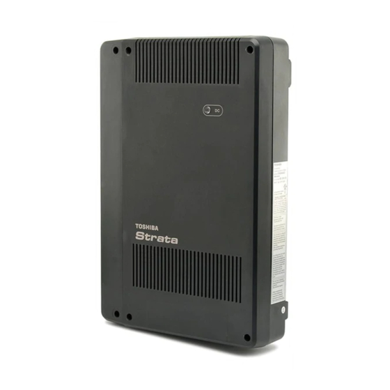
CIX40 Installation CIX40 System Cabinet Versions CIX40 System Cabinet Versions The CIX40 system is available on three hardware versions. The Release 1 cabinet is labeled CHSU40A. The Release 2 is labeled CHSU40A2. The Release 3 is labeled CHSU40A3. The system label is on the outside of the CIX40 cabinet on the right side. Throughout this manual R1 HW and R2 HW refer to the earlier (CHSU40A and CHSU40A2) systems and R3 HW refers to the later CHSU40A3 systems. -
Page 13: Cix40 Release 1 Cabinet System Capacities
CIX40 Installation CIX40 System Cabinet Versions CIX40 Release 1 Cabinet System Capacities CIX40 R1 Hardware systems can be upgraded to Release 5.20 software. The GCTU2 processor comes with a built-in maintenance modem (AMDS), one Music on Hold (MOH) interface, one IP interface (NIC), one External Paging interface, one relay contact, and one Secure Digital card slot. -
Page 14: Cix40 R5.20 Software
CIX40. IP Ports on the optional GIPH and MIPU cards, and more than four (up to eight) voice mail require licensing on the GCTU2A processor as follows: Each Toshiba IPT2000 anf IP5000 series telephone and SIP Telephone requires one LIC-CIX- •... -
Page 15: Cix40 Cabinet Specifications
Use PROG 103-38 to enable a COS to receive OCA. Use PROG 200-04 to put the telephone in a COS that is enabled to receive OCA. Toshiba IP Telephones, Soft IPT and SIP phones are supported by the CIX40. Strata CIX40 R3 Installation & Maintenance... - Page 16 CIX40 Installation Telephone Compatibility The figure below displays the interior layout of the CIX40. The figures shows a GMAU2, this is a CIX40-with R1 hardware. A CIX40 with R2 hardware would have a GMAU3 instead of the GMAU2. A CIX40 with R3 hardware would have a GMAU4 instead of the GMAU2 shown. SD™...
-
Page 17: Inspection
CIX40 Installation Inspection Inspection 1. When the system is received, examine all packages carefully and note any visible damage. If any damage is found, do not open the packages. Contact the delivery carrier immediately and make the proper claims. 2. After unpacking (and before installing), check the system against the packing list and inspect all equipment for damage. -
Page 18: Site Requirements
A dedicated AC power circuit eliminates interference from branch circuit motor noise or the like, and to prevent accidental power-off. To avoid accidental power turn-off, Toshiba recommends that you do not use an On/Off wall switch on this dedicated AC circuit. - Page 19 CIX40 Installation Site Requirements Table 1-4 provides a summary of the electrical and environmental characteristics. Table 1-4 Summary of Electrical/Environmental Characteristics CIX40 Primary Power (Power Supply Specification) Specification R1 and R2 Hardware R3 Hardware Input AC 105~125VAC 105~125VAC AC frequency 50/60 Hz 50/60 Hz AC input current...
-
Page 20: Ac Power And Grounding Requirements
CIX40 Installation AC Power and Grounding Requirements AC Power and Grounding Requirements The CIX40 requires an earth ground connection for proper operation. The ground for the CIX40 must originate at the building’s main power distribution panel and have a solid connection to earth ground. -
Page 21: Ground Wire Connection
CIX40 Installation AC Power and Grounding Requirements Ground Wire Connection The ground wire must have a customer supplied closed or eye type lug for connection to the GMAU terminal TB3. Refer to Figure 1-5. The connector lug must be crimped onto the wire. The connection must be mechanical. -
Page 22: Installing The Cix40 Cabinet
CIX40 Installation Installing the CIX40 Cabinet Installing the CIX40 Cabinet Check the items shipped. CHSU40A (R1 HW), CHSU40A2 (R2 HW), or CHSU40A3 (R3 HW) cabinet • • GMAU2 (R1 HW), GMAU3 (R2 HW) or GMAU4 (R3 HW) motherboard and GCTU2 processor AC adapter •... - Page 23 CIX40 Installation Installing the CIX40 Cabinet 3. Place the cabinet base on the desired location on the mounting surface and mark the location of the four screw holes. See Figures 1-7 and 1-8. 4. Using a hard board between the cabinet and the wall, secure the hard board to the wall first, making certain that screws are aligned with studs.
- Page 24 CIX40 Installation Installing the CIX40 Cabinet Step 1: Install Power Wiring Important! Ensure that you have the correct power adapter for the cabinet being installed. R1 and R2 HW (GMAU2/3) use factory-shipped AC adapter SQ60W15P-00 R3 HW (GMAU4) use factory-shipped AC adapter ACADP40-1A 1.
-
Page 25: Cix40 Cabinet Slots
CIX40 Installation CIX40 Cabinet Slots CIX40 Cabinet Slots The CIX40 Cabinet has a dedicated slot for the GCTU2 system processor card. Dedicated slots for the optional GVPH1 voice mail PCB and the IP interface PCBs (GIPH, GIPU8, MIPU16, or MIPU24) or the GCOCIH1 four CO line PCB are under the GCTU2. All other CIX40 optional interface cards plug onto the Processor or the Motherboard. - Page 26 CIX40 Installation CIX40 Cabinet Slots GCTU2 removed for clarity. GIPH, GIPU8, Note: This photo shows the GIPH MIPU, or card installed. The GCOCIH card GCOCIH can be installed in this slot. GVPH1 IP, CO Line Card Stopper GMAU3 Refer Figure 1-18 on Page 1-33.
-
Page 27: Printed Circuit Boards
CIX40 Installation Printed Circuit Boards Printed Circuit Boards This section contains detailed descriptions of each printed circuit board (PCB) available for the Strata CIX40 system. PCB Descriptions The tables below summarize the CIX40 cabinet PCBs (see Table 1-6 Figure 1-11.) A detailed description follows. -
Page 28: Cix40 Processor
CIX40 Installation CIX40 Processor Table 1-7 Circuit Card Compatibility R4 Software R5.20 Software Card Type Card CIX40 CIX40 CIX40 CIX40 R1 HW R1 HW R2 HW R3 HW Processor GCTU2 Mother sub-assembly GMAS2 — — Mother sub-assembly GMAS3 — — —... -
Page 29: Gctu2 Processor Interfaces
External Page Interface A 600 ohm RCA jack is built into the processor to interface with a Toshiba External Amplified Speaker (HESB or BESCB) or a customer-supplied page amplifier and speaker(s) for external paging, night ring over external page, and external BGM applications. - Page 30 CIX40 Installation CIX40 Processor CIX40 Processor Optional Subassembly Optional BSIS (Serial Port Interface) subassembly – can be attached to the GCTU2 processor to provide up to four RS-232 interface ports; one port for an SMDR interface to Call Accounting devices, one port for SMDI to external voice mail devices, and two other applications. Note The GVPH1 does not require a BSIS SMDI port.
-
Page 31: Ip Interface Cards
CIX40 Installation IP Interface Cards IP Interface Cards The features of the CIX40 system IP interface cards are shown in the table below. Feature GIPH GIPU8 MIPU16 MIPU24 Collect log files remotely Restriction by tail length of Echo Canceller Quality of Service (QoS) threshold alarm SIP Trunk Support IP Mobility Support... -
Page 32: Gcocih
CIX40 Installation GCOCIH GCOCIH The GCOCIH1 assembly provides four loop-start CO line circuits. Refer to Figure 1-19. The GCOCIH1 card plugs into the GMAS sub-mother board. This is the slot adjacent to the voice mail card. When the GCOCIH1 card is installed an IP interface card cannot be installed in the system. GCOCIH1 assembly specifications: Loop-start CO Line Circuits •... -
Page 33: Gvph
CIX40 Installation GVPH GVPH The GVPH is a four, six or eight port voice mail system on a card. The first four port licenses are included in the CIX40 system. Two additional two-port licenses (LIC-2 GVPH) can be added. Earlier versions, the GVPH-V1 card have status indicators for only the first four ports. Later versions, the GVPH-V2 have eight indicators. -
Page 34: Pcb Installation
CIX40 Installation PCB Installation PCB Installation Overview Instructions The following is an overview for installing the Printed Circuit Boards (PCBs) into the Strata CIX40. After reading this section, proceed to the step-by-step instructions for each PCB. CAUTION! You must remove power from the CIX40 system before installing or removing printed circuit cards. -
Page 35: Detailed Pcb Installation
CIX40 Installation Detailed PCB Installation Detailed PCB Installation This section includes the detailed installation steps for the CIX40 system PCBs. Step 1: Set Switches on the GMAU2/GMAU3/GMAU4 (Motherboard) 1. The GMAU2 (shown in Figure 1-13) supports up to 3 CO lines with Caller ID (CLID). Each circuit has an associated pad switch. - Page 36 CIX40 Installation Detailed PCB Installation Table 1-9 GMAU2 Controls, Switches and Indicators Control/Indicator/ Type of Component Description Connector Power Switch: [STANDBY] = no DC power supply. 2-position slide switch [ON] = DC voltage supplied. [ON] activates the reserve power from HPFB-6 battery pack.
- Page 37 CIX40 Installation Detailed PCB Installation On Standby (Off) Cct 1/2 Cct 3/4 SW400 SW500 SW600 SW800 SWx00 0 dB Figure 1-14 GMAU3 (R2 HW) 1-27 Strata CIX40 R3 Installation & Maintenance 05/10...
- Page 38 CIX40 Installation Detailed PCB Installation Cct 1/2 Cct 3/4 SW400 SW500 SW600 SW800 SWx00 0 dB Figure 1-15 GMUA4 (R3 HW) Table 1-10 GMAU3 and GMAU4 Controls, Switches and Indicators Control/Indicator/ Type of Component Description Connector Power Switch: [STANDBY] = no DC power supply. 2-position slide switch [ON] = DC voltage supplied.
- Page 39 CIX40 Installation Detailed PCB Installation Table 1-10 GMAU3 and GMAU4 Controls, Switches and Indicators (continued) Control/Indicator/ Type of Component Description Connector 50-pin Amphenol DKT, SLT and Power Failure Transfer connector interface 44-pin DIN connector GMAS (sub-motherboard) interface 16-pin female connector 13-pin female GCDU2 DKT and loop start interface connector...
- Page 40 CIX40 Installation Detailed PCB Installation Step 2: GVPH1 Voice Mail PCB (optional) The first four ports on the GVPH1 do not require a license. The first four port licenses are included in the CIX40 system. Two additional two-port licenses (LIC-2 GVPH) can be added for ports 5 and 6, and ports 6 and 7.
-
Page 41: Voice Mail And Telephone Lcd Prompts
CIX40 Installation Detailed PCB Installation SW1 - Language Selection Switch Status Channel in-use indicators Battery Jumper - Located near the edge of the AMDS1 on the GVPH1. Figure 1-16 GVPH1 Card (Earlier Version shown) Modem Connector Status SW1 - Language Selection Switch Battery Jumper Figure 1-17 GVPH1 Card (Later Version shown) Voice Mail and Telephone LCD Prompts... - Page 42 CIX40 Installation Detailed PCB Installation From each telephone set: To change the language display on the telephone LCD, Dial #4951 for English. • To change the language display on the telephone LCD, Dial #4954 for Spanish. • Use eManager: To set the Telephone LCD language use eManager > Station > Assignments > DKT (Program •...
-
Page 43: Remote Connection
CIX40 Installation Detailed PCB Installation Remote Connection Remote communication to the GVPH1 requires the installation of a modem on the UADM PC (if a modem does not already exist). The GVPH1 comes equipped with an internal modem (AMDS daughter board) of 33.6 Kbps baud and does not require any additional equipment. UADM PC Modem Prepare the UADM PC by installing, connecting and configuring a modem. - Page 44 CIX40 Installation Detailed PCB Installation GCOCIH1 CO Line Interface PCB Installation (optional) The GCOCIH1 provide four loop start CO Line circuits. The GCOCIH1 card plugs into the GMAS sub-mother board. This is the slot adjacent to the voice mail card. When the GCOCIH1 card is installed an IP interface card cannot be installed in the system.
- Page 45 CIX40 Installation Detailed PCB Installation Install the GIPH or GIPU8 IP Interface PCB (optional) When the GIPH1 or GIPU8 or an MIPU card is installed, a GCOCIH1 (four circuit CO Line interface) cannot be installed. For MIPU installation refer to “Install the MIPU 16 or 24-Channel IP Interface PCB (optional)”...
- Page 46 CIX40 Installation Detailed PCB Installation Install the MIPU 16 or 24-Channel IP Interface PCB (optional) When the GIPH1, GIPU8, or an MIPU card is installed, a GCOCIH1 (four circuit CO Line interface) cannot be installed. 1. Turn off system power. 2.
- Page 47 CIX40 Installation Detailed PCB Installation 6. Install the MIPU into the GMAS (sub-motherboard) (see Figure 1-11 Figure 1-21). 7. If you are installing a GVPH insert that card now. Otherwise, refer to “Install the GCTU2 (Processor)” on page Note To program the MIPU, refer to the Strata CIX Programming Manual Volume 1 and use eManager.
- Page 48 CIX40 Installation Detailed PCB Installation Step 4: Install the GCTU2 (Processor) The GCTU2 is the main processor for the CIX40. It is shipped in a separate box, not in the CIX40 cabinet. The GCTU2A is considered a unit, separate from the cabinet for repair, return and warranty purposes.
- Page 49 Network interface port (LAN port) Table 1-16 SecureDigital Memory Cards Manufacturer Type Capacity Model 64MB SD-M64B1 128MB SD-M128 Normal 256MB SD-M256 512MB SD-M512 TOSHIBA 128MB SD-F128 256MB SD-F256 High speed 512MB SD-M512 SD-M01G 64MB AB0407RP 128MB AK04278V2 Normal 256MB AR0408RF...
- Page 50 CIX40 Installation Detailed PCB Installation Step 5: Install the GCDU2 (DKT and Loop Start Interface) The GCDU2 PCB adds an additional 3 CO lines, 3 Caller ID units, and 8 digital telephone circuits with a single PCB. It attaches to the GMAU2/3/4 motherboard. With the GCDU2 installed, the CIX40 supports up to 16 digital telephones (DKTs), 7 CO lines with Caller ID (GMAU3/4) or 6 CO lines with Caller ID (GMAU2).
- Page 51 CIX40 Installation Detailed PCB Installation Cct1/2 CO4/Cct1 Cct3/4 CO5/Cct2 CO6/Cct3 0006-pcb Figure 1-24 GMAU3 with GCDU2 Installed Table 1-17 GCDU2 Controls, Indicators and Connectors Control/Indicator/ Type of Description Connector Component SW400 2-position slide SW500 3dB Pad switch switch SW600 16-pin male connector 12-pin male connector...
- Page 52 CIX40 Installation Detailed PCB Installation Step 6: Install the GSTU1 The GSTU1 provides one additional standard telephone interface. The GSTU1 does not require a license. To install the GSTU1, align the GSTU1 pins over the GMAU2/3/4 motherboard and press down firmly.
- Page 53 CIX40 Installation Detailed PCB Installation Step 7: Install the BSIS (optional) The BSIS provides four RS-232 serial ports. To install the BSIS, align the BSIS pins over the GCTU2 and press down firmly (see Figure 1-22). Note that if the BSIS card has an “Up Arrow” it will be pointed down. This is normal, it does not require adjustment, refer to Figure 1-26.
- Page 54 CIX40 Installation Detailed PCB Installation 2. Mark the location of the two screw holes, then drill holes. 3. Screw the two screws two-thirds into the mounting surface. 4. Hang the HPFB-6 on the screws then tighten the screws into the mounting surface. 5.
- Page 55 CIX40 Installation Detailed PCB Installation Battery Cable Connector HPFB Ground Wire Battery Cable HPFB Ground Wire ON / Standby ON / Standby Switch Switch GMAU2/3 GMAU4 Figure 1-27 HPFB-6 Connection 1-45 Strata CIX40 R3 Installation & Maintenance 05/10...
- Page 56 CIX40 Installation Detailed PCB Installation To P10 Connector (see Fig. 1-2) 2“ #10 AWG HPFB FG Wire to TB1 (see Fig. 1-2) HPFB Unit: Reserve Power Battery and Charger (optional) 7253 From Second HPFB (optional) 2“ 2“ 2“ Figure 1-28 HPFB-6 Reserve Power Installation 1-46 Strata CIX40 R3 Installation &...
-
Page 57: Digital Telephone Connection
CIX40 Installation Digital Telephone Connection Digital Telephone Connection The Strata CIX40 supports any Toshiba 2000, 3000, 3200, DP5000-series digital telephones. The DP5022-SDM telephone is shown right. Strata CIX40 systems running R5.1 and later SW support the DP5000-series telephones. The DP5022-SDM only works on the CIX40 without a license. -
Page 58: Loop Limits
CIX40 Installation Loop Limits Loop Limits This section provides the maximum loop lengths for connection of telephones, lines, peripheral equipment, and power supplies. The following information applies to only the Strata CIX40 system refer toTable 1-20 for standard analog connections and Table 1-21 for digital station circuits. -
Page 59: Cix40 Secondary Protection
CIX40 Installation CIX40 Secondary Protection CIX40 Secondary Protection The following diagram (see Figure 1-30) shows where secondary protectors must be installed for outside wiring. Figure 1-30 CIX40 Secondary Protector Diagram Important! To protect against transient voltages and currents, solid state secondary protectors must be installed if there is outside wiring. -
Page 60: Mdf Wiring
CIX40 Installation MDF Wiring MDF Wiring This section details the CIX40 system MDF wiring. Station Wiring Cross-connect or MDF wiring for the digital telephones, the single line analog stations, and the power-fail station are all made through the 25-pair connector on the GMAU PCB. Refer to Table 1-22. -
Page 61: Co Line Circuit Wiring
CIX40 Installation MDF Wiring CO Line Circuit Wiring CO line circuit connectors are on the GMAU and the optional GCDU and GCOCIH PCBs. Refer to Table 1-22 for GMAU2 and GCDU2 connectors. Note that the R2 HW, the GMAU3 and the GCOCIH PCBs have two CO line circuits per connector. - Page 62 CIX40 Installation MDF Wiring Table 1-23 CO Line Circuit Connector Labels 1-52 Strata CIX40 R3 Installation & Maintenance 05/10...
-
Page 63: Gvph1 Administration Pc Connections
GVPH1 Administration PC Connections Strata CIX40 6-wire Modular Cord - telephone cross-pinned type (modular jack locking tabs on the same side of the cord). Toshiba PPTC or PPTC9 connectors to PC COM port GVPH RS232C Jack PC with GVPH XADM Software... - Page 64 This page is intentionally left blank.
-
Page 65: Chapter 2 - Cix40 Default Database
CIX40 Default Database CIX40 Release 5.10 and later software initializes with a default database that is different than the previous releases. CIX40 R1 HW, R2 HW, and R3 HW Systems The system is pre-programmed with a limited database that allows the system function from initial power-up for easy, cost effective installation. -
Page 66: Cix40 Default Initialized Data
CIX40 Default Database CIX40 Default Initialized Data CIX40 Default Initialized Data This section applies to systems running R5.10 or later software. The information in Table applies to the GCTU2A processor card IP connection. Table 2-1 Prog 916 – System IP Address Default Data IP Address 192.168.254.253 Subnet Address... - Page 67 CIX40 Default Database CIX40 Default Initialized Data • The default programming data shown in Table 2-3 applies even if the option units (GCDU2/ GSTU1/GVPH1) are not mounted. This enables voice mail to be used as is if the GVPH1 is inserted.
- Page 68 CIX40 Default Database CIX40 Default Initialized Data Table 2-8 Program 100 Default Data — GMAU2 -- R1 HW System with R5.1 SW Equip. Station / Line Circuits Connection Nos. Numbers Code 0101 8 - Digital Telephones (no speaker OCA) 200~207 GMAU2 0102 3 - CO lines with CLID...
- Page 69 CIX40 Default Database CIX40 Default Initialized Data Table 2-10 Program 100 Default Data — GMAU3/4 -- R2/R3 HW System Equip. Station / Line Circuits Connection Nos. Numbers Code 0101 8 - Digital Telephones (no speaker OCA) 200~207 GMAU3/4 (motherboard) 0102 4 - CO lines, with CLID CO1~CO4 0103...
- Page 70 CIX40 Default Database CIX40 Default Initialized Data Table 2-12 Prog 200 Default Data for GCDU2 GCDU2 GSTU1 EQUIP 010701 010702 010703 010704 010705 010706 010707 010708 010402 Ext. Ext. Ext. Ext. Ext. Ext. Ext. Ext. Ext. FB19 VM ID VM MW FB22 Center Port...
- Page 71 CIX40 Default Database CIX40 Default Initialized Data Table 2-15 Prog 579 Default Data FB04 Output of Class, ANI and DNIS 1 (Enable) Same as CIX100 FB05 Calling Number Digits Sent to VM Do NOT change for GVPH1 FB16 VMDN (Distributed Hunt Group Pilot) Message Center Call-back Same as CIX100 FB19...
- Page 72 CIX40 Default Database CIX40 Default Initialized Data Table 2-20 Prog 300 Default Data - GMAU3/4 FB12 TRK NO. EQUIP Hunt Order 010201 DTMF LOOP 010202 DTMF LOOP 010203 DTMF LOOP 010204 DTMF LOOP 010501 DTMF LOOP 010502 DTMF LOOP 010503 DTMF LOOP Table 2-21 Prog 300 Default Data - GMAU3/4 with GCOICH...
- Page 73 CIX40 Default Database CIX40 Default Initialized Data Table 2-23 Prog 310 Default Data - GMAU2 with GCOICH (Trunk > Assignment > DIT) Trunk Day 1 Day 2 Night Music On Hold Number EQUIP Destination Destination Destination Source 010201 No Data No Data No Data Processor MOH Jack...
- Page 74 CIX40 Default Database CIX40 Default Initialized Data Table 2-26 Prog 304 Default Trunk Group Group Number Group Type 1 (Analog) Line Type 1 (CO) CO Service Type Table 2-27 Prog 306 Default Trunk Type Group Number Group Type 1 (Analog) Trunk Type 1 (CO) 2-10...
- Page 75 CIX40 Default Database CIX40 Default Initialized Data Table 2-28 Prog 107 Default PAD Table Values 10 11 12 13 14 15 16 17 18 Receiver Sender Analog Telephone Analog Trunk T1 trunk ISDN Station No Change to these default values ISDN Trunk Conference Bridge Music Source...
-
Page 76: Ip Default Data For Giph1/Gipu8/Mipu Card
CIX40 Default Database CIX40 Default Initialized Data IP Default Data for GIPH1/GIPU8/MIPU Card The following applies when the GIPH1, GIPU8, or MIPU card is installed. Table 2-29 Prog 161 – IP Default Data FB No. Parameter R1 HW R2 HW Cabinet and Card Slot Number 0106 0105... -
Page 77: Call Monitor
CIX40 Default Database Call Monitor Call Monitor Using the flexible Call Monitor button on your telephone, you can listen to the message a caller is recording in your voice mailbox. You can also answer the call and talk to the caller anytime during the message recording. - Page 78 This page is intentionally left blank.
-
Page 79: Chapter 3 - Cix40 Ip Telephony
IP Telephone installation are covered, in detail, in the Strata CIX and MAS Installation and Maintenance Manual. The GIPU8, GIPH and MIPU printed circuit boards (PCB) provide the interface for Toshiba IPT telephones, SIP telephones, the Strata MAS for SES and ACD, and StrataNet applications. -
Page 80: Install The Ip Interface Card
CIX40 IP Telephony Install the IP Interface Card Install the IP Interface Card The CIX40 R2 system has a single card slot for the IP interface. This card can be any one of the following: Card IP Ports Comments GIPH G.729A and 32 ms echo = 6 ports GIPU8 Tail-length echo cancellation increased from 32... -
Page 81: Install Ip Telephones
The IP Telephone (IPT) sets require external power. The power supply can be from an AC adapter or the LAN using a Power Over Ethernet (POE). POE must meet IEEE802.3af standard. Toshiba recommends the SMC6824MPE PoE switch. Refer to “Power over LAN” in the CIX and MAS Installation and Maintenance Manual. - Page 82 This is the last page of the document.