
Related Manuals for Agilent Technologies E6198B


Summary of Contents for Agilent Technologies E6198B
- Page 1 Agilent TS-5000 Functional Test System E6198B Switch/Load Unit User Manual Agilent Technologies...
-
Page 2: Safety Notices
Edition 4 (E8770-90020 Revision 2) mance of this document or of any met. January 2006 information contained herein. Should Agilent and the user have a separate This manual covers the written agreement with warranty following Agilent WA R N I N G... -
Page 3: Table Of Contents
Operator Safety Information Safety Symbols and Regulatory Markings End of Life: Waste Electrical and Electronic Equipment (WEEE) Directive 2002/96/EC Switch/Load Unit and Plug-In Cards E6198B Standalone/Integrated Switch/Load Unit Rating Electrical Mechanical E6198B Standalone Switch/Load Unit Description USB Interface Digital I/O... - Page 4 Connecting an Additional (Spare) Power Supply Configuring the Power Busses Setting the UUT Power Supply Remote/Local Sense Jumpers Configuring the Current-Sense Jumpers 4-10 Connecting E6198B to the Computer via USB Interface or Parallel Port 4-12 Adding a Second Switch/Load Unit 4-13...
- Page 5 Local / Remote Sensing 5-57 Selecting a Load Fuse 5-57 Current Monitor 5-58 Selecting and Loading Flyback Protection 5-58 Protection Devices 5-59 Load and UUT Connections 5-60 Using the Agilent N9377A 16-Channel Dual-Load Load Card 5-62 E6198B Switch/Load Unit User Manual...
- Page 6 5-73 Current Sharing 5-74 External Load Mounting Options 5-74 UUT Connections 5-75 Using the Agilent N9378A 24-Channel Low Resistance Load Card 5-76 Selecting a Power Supply Configuration 5-79 Using the Power Switches as General Purpose Relays 5-79 Connecting Loads 5-80...
- Page 7 Agilent E6177A 24-Channel Medium-Current Load Card Specifications Agilent U7177A 24-Channel Medium-Current Load Card Specifications Agilent E6178B 8-Channel Heavy Duty Load Card Specifications Agilent N9377A 16-Channel Dual-Load Load Card Specifications Agilent N9378A 24-Channel Low-Resistance Load Card Specifications E6198B Switch/Load Unit User Manual...
- Page 8 Agilent E6175A 8-Channel High-Current Load Card B-11 Agilent E6176A 16-Channel High-Current Load Card B-15 Agilent E6177A 24-Channel Medium-Current Load Card B-19 Agilent U7177A 24-Channel Medium-Current Load Card With Current Sense B-23 Agilent E6178B 8-Channel 30 Amp Load Card Register Definitions B-28...
- Page 9 Pin Matrix Card Register Definition B-57 Agilent E8792A and E8793A Pin Card Register Definitions B-57 Agilent E8782A 24-Instrument, 40-Measurement Matrix Card B-65 Agilent E8783A 64-Pin Matrix Card B-74 Agilent E8794A Custom Card Register Definitions B-83 Repair Information Support Strategy Locating Load Card Components...
- Page 10 THIS PAGE IS INTENTIONALLY LEFT BLANK. E6198B Switch/Load Unit User Manual...
-
Page 11: List Of Figures
List of Figures Legal Information Safety and Regulatory Information Switch/Load Unit and Plug-In Cards Figure 3-1. Agilent E6198B Standalone Switch/Load Unit Front View Figure 3-2. Agilent E6198B Standalone Switch/Load Unit Back View Figure 3-3. Digital Input Example Figure 3-4. Digital Output Example Figure 3-5. - Page 12 5-52 Figure 5-38. Agilent U7177A 24-Channel Medium-Current Load Card UUT Connections 5-53 Figure 5-39. Agilent E6178B 8-Channel Heavy Duty Load Card Block Diagram 5-55 Figure 5-40. Agilent E6178B 8-Channel Heavy Duty Load Card Layout 5-56 Figure 5-41. Typical Agilent E6178B Load Card Flyback Protection Circuit...
- Page 13 Figure 5-42. Agilent E6178B Load Card Wiring 5-61 Figure 5-43. Agilent N9377A 16-Channel Dual-Load Load Card Block Diagram 5-63 Figure 5-44. N9377A 16-Channel Load Card Layout 5-64 Figure 5-45. N9377A Load Card - Flyback Locator and Polarity Orientation 5-66 Figure 5-46. N9377A Load Card - Flyback Circuit Detail 5-67 Figure 5-47.
- Page 14 Figure 7-1. Custom Card Features Figure 7-2. J2 Configuration Lines Pinouts Figure 7-3. J3/J4 Breakouts for Agilent E1418 DAC Figure 7-4. J3 or J4 Connector Breakouts for Agilent E6174 Event Detector Figure 7-5. J5 and J6 Breakouts (32-Pin Matrix Cards) Figure 7-6. E8794A Layout Figure 7-7.
-
Page 15: List Of Tables
List of Tables Legal Information Table 1-1. Agilent Sales And Support Contact Numbers Safety and Regulatory Information Table 2-1. Environment Requirements Table 2-2. Safety Symbols and Regulatory Markings Switch/Load Unit and Plug-In Cards Table 3-1. Switch/Load Unit Rating (Electrical) Table 3-2. Switch/Load Unit Rating (Mechanical) Table 3-3. - Page 16 Table C-3. Bypass and Disconnect Relays Table C-4. Miscellaneous Relays Table C-5. Measurement Matrix Relays for E8782A Table C-6. Measurement Matrix Relays for E8783A C-10 Table C-7. Bypass and Disconnect Relays for E8782A and E8783A C-12 Glossary Of Terms E6198B/E6218A Switch/Load Unit User Manual...
-
Page 17: Declaration Of Conformity
Agilent TS-5000 E6198B Switch/Load Unit User Manual Declaration of Conformity Agilent Technologies... - Page 18 Agilent Technologies website. You can search for the DoC by its product model or description at the following web address: http://regulations.corporate.agilent.com/DoC/search.htm If you are unable to locate the DoC, please contact your local Agilent N O T E representative. E6198B Switch/Load Unit User Manual...
- Page 19 Agilent TS-5000 E6198B Switch/Load Unit User Manual Legal Information Warranty Technology Licenses Restricted Rights Legend Service And Support Agilent On The Web Agilent By Phone Agilent Technologies...
-
Page 20: Legal Information
Should Agilent and the user have a separate written agreement with warranty terms covering the material in this document that conflict with these terms, the warranty terms in the separate agreement shall control. -
Page 21: Service And Support
Agilent By Phone If you do not have access to the Internet, call one of the numbers in Table 1-1 Table 1-1 Agilent Sales And Support Contact Numbers Canada (877) 894-4414 Americas Latin America... -
Page 22: Table 1-1. Agilent Sales And Support Contact Numbers
Legal Information Table 1-1 Agilent Sales And Support Contact Numbers (continued) Austria 01 36027 71571 Belgium 32 (0) 2 404 93 40 Denmark 45 70 13 15 15 Finland 358 (0) 10 855 2100 0825 010 700* France *0.125 €/minute... - Page 23 Agilent TS-5000 E6198B Switch/Load Unit User Manual Safety and Regulatory Information Safety Information Safety Summary Safety Notice General Environmental Conditions Before Applying Power Ground The System Fuses Operator Safety Information Safety Symbols and Regulatory Markings End of Life: Waste Electrical and Electronic Equipment (WEEE) Directive...
-
Page 24: Safety And Regulatory Information
Failure to comply with these precautions or with specific warnings elsewhere in this manual violates safety standards of design, manufacture, and intended use of the instrument. Agilent Technologies, Inc. assumes no liability for the customer's failure to comply with these requirements. -
Page 25: Environmental Conditions
The protection provided by the Agilent TS-5000 system may be WA RNING impaired if the system is used in a manner not specified by Agilent. -
Page 26: Ground The System
(High, Low or Guard). Assure the equipment under test has adequate insulation WA RNING between the cable connections and any operator-accessible parts (doors, covers, panels shields, cases, cabinets, etc.) E6198B Switch/Load Unit User Manual... -
Page 27: Safety Symbols And Regulatory Markings
Protective earth (ground) terminal Frame or chassis terminal Terminal is at earth potential. Used for measurement and control circuits designed to be operated with one terminal at earth potential. Switch setting indicator. O = Off, | = On. E6198B Switch/Load Unit User Manual... - Page 28 The CE mark is a registered trademark of the European Community. This CE mark shows that the product complies with all the relevant European Legal Directives. E6198B Switch/Load Unit User Manual...
-
Page 29: End Of Life: Waste Electrical And Electronic Equipment (Weee) Directive 2002/96/Ec
With reference to the equipment types in the WEEE directive Annex 1, this product is classified as a “Monitoring and Control Instrumentation” product. Do not dispose in domestic household waste To return unwanted products, contact your local Agilent office, or see: http://www.agilent.com/environment/product for more information. - Page 30 Safety and Regulatory Information THIS PAGE IS INTENTIONALLY LEFT BLANK. E6198B Switch/Load Unit User Manual...
- Page 31 Backplane And Breakout Board Connectors and LEDs 3-10 Differentiating E6198B Standalone Option and System Integrated Option 3-21 This chapter gives an overview of the Agilent E6198B (Standalone and Integrated) Switch/Load Unit (SLU), load cards, and other associated equipment. Agilent Technologies...
-
Page 32: Switch/Load Unit And Plug-In Cards
Switch/Load Unit and Plug-In Cards E6198B Standalone/Integrated Switch/Load Unit Rating Electrical Table 3-1 Switch/Load Unit Rating (Electrical) Parameter Value Input Voltage 100–240 VAC nominal Frequency 50/60 Hz Power 325 W maximum Mechanical Table 3-2 Switch/Load Unit Rating (Mechanical) Parameter Value Width 484.64 mm... -
Page 33: E6198B Standalone Switch/Load Unit Description
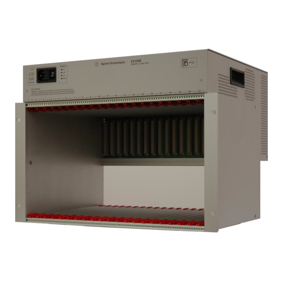
Figure 3-1 consists of a standard VME type enclosure, a custom high current backplane, and slots for up to 21 optional Agilent plug-in cards. The following plug-in cards are available: • Agilent E6175 8-channel load card • Agilent E6176A 16-channel load card •... -
Page 34: Figure 3-1 Agilent E6198B Standalone Switch/Load Unit Front View
Switch/Load Unit and Plug-In Cards Figure 3-1 Agilent E6198B Standalone Switch/Load Unit Front View Figure 3-2 Agilent E6198B Standalone Switch/Load Unit Back View In addition to holding load cards, pin matrix cards and custom cards, the Switch/Load Unit also provides the following capabilities. -
Page 35: Usb Interface
(Spare Digital Out). There is no handshaking capability in the digital I/O. Typical usage of the digital I/O includes: Automation control Digital control of circuitry on the Agilent E8794A Custom Card Digital switches (for example, to indicate door open/closed) Actuator control... -
Page 36: Open Drain Digital Output
+5V, +12V and -12V from the Switch/Load Unit Power Supply. The +5V supply can deliver 7.5A to 30A, +12V supply can deliver 2.5A to 12.5A, the -12V supply can deliver 700mA to 1A. You can E6198B Switch/Load Unit User Manual... -
Page 37: Current Sense
“Connecting an Additional (Spare) Power Supply for details. Power supplies +5V, +12V and -12V for E6198B have non-resettable N O T E fuses. Spare supply has resettable fuse. If an overload occurs, the fuse(s) open. To reset the fuse(s), remove power from the Switch/Load Unit for approximately 20 seconds. -
Page 38: Figure 3-5 Switch/Load Unit Block Diagram
Load Card #2 Pin Matrix Card #2 Load Card #n Pin Matrix Card #n Note: All plug -in cards are optional --the mix and numbers of cards in your system will be different than shown here E6198B Switch/Load Unit User Manual... -
Page 39: E6198B Integrated Switch/Load Unit Description
Switch/Load Unit and Plug-In Cards E6198B Integrated Switch/Load Unit Description The Agilent E6198B now comes as a system integrated unit or a standalone unit. The features and functionality remains the same as the previous E6198A. Differences between the two are in the cabling and function selection panel. -
Page 40: Backplane And Breakout Board Connectors And Leds
LEDs. These components are described on the following pages. See Table 3-3 for more detail. Figure 3-7 Switch/Load Unit Backplane Connectors (USB port adaptor board Not Shown) 3-10 E6198B Switch/Load Unit User Manual... -
Page 41: Figure 3-8 Switch/Load Unit Breakout Board Connectors (Standalone Only)
Figure 3-8 Switch/Load Unit Breakout Board Connectors (Standalone only) S2A-S2H S3A-S3F S1A-S1D FRONT BACK BREAKOUT BOARD (External Board) The breakout panel is available with the E6198B Standalone option and is easily accessible from the SLU rear. E6198B Switch/Load Unit User Manual 3-11... -
Page 42: Backplane Connector Name
Switch/Load Unit and Plug-In Cards Backplane Connector Name Table 3-3 lists the connectors on a E6198B backplane. Table 3-3 Backplane Connectors for E6198B E6198B Reference Designator Description SLU Current Sense: Bussed/Split SLU Power Bus Sense Select: Local/Remote Frame Select T1-T14... -
Page 43: Breakout Board Connector Name (For E6198B Standalone Option)
S1A-S1D Toggle switches for Local/Remote S2A-S2H Toggle switches for Frame Select S3A-S3F Toggle switches for Isense Bussed/Split The breakout board is not available with E6198B System Integrated N O T E option. See Figure 3-6. E6198B Switch/Load Unit User Manual... -
Page 44: Backplane Connectors
J801 and J802 provide the high power connections to power busses PB1-PB4. Three supplies with a common connection to PB1 or two independent supplies can be configured on the four power busses. Bulk bypassing between power busses may be desirable in certain applications. 3-14 E6198B Switch/Load Unit User Manual... -
Page 45: Backplane Leds
Switch/Load Unit backplane connector J102 carries such signals as the Digital I/O, DAC 1 and 2, and the ISense (current sense) lines. When configured as part of a standard Agilent system, J102 of the Switch/Load Unit is connected via cable to a mass interconnect panel. -
Page 46: Figure 3-9 Switch/Load Unit J102 Connector Pinouts
4 8 4 5 3 9 3 6 3 0 2 7 2 4 2 1 1 5 1 2 For E6198B Standalone option, connector J102 is extended from the N O T E backplane to the breakout board. See Figure 3-8. -
Page 47: Figure 3-10 Cable Connector Pinouts
Row 27 -12 Vdc Supply Spare Supply Row 28 System Gnd System Gnd Row 29 System Gnd System Gnd Row 30 No Connection No Connection Row 31 System Gnd DAC1 Row 32 System Gnd DAC2 E6198B Switch/Load Unit User Manual 3-17... -
Page 48: Table 3-6 J102 Signal Definitions
Two or more sets of the above lines can be bussed together select from toggle switches. Refer to page 12 for details. Power Bus Sense 1 - 4 The remote sense lines for the power supplies connected to power buses 1 - 4. Chassis ground of the Switch/Load Unit. 3-18 E6198B Switch/Load Unit User Manual... -
Page 49: J1 Pinout
Local 1 is selected if LOC_S1 is connected with PB1; Remote 1 is selected if REM_S1 is connected with PB1, and so on. Default setting for J3 is Local. Table 3-9 Switch/Load Unit J3 Pinout LOC_S1 REM_S2 LOC_S3 REM_S4 LOC_S1 REM_S1 LOC_S2 REM_S3 LOC_S4 E6198B Switch/Load Unit User Manual 3-19... -
Page 50: T1-T14 Slu Logic Power Supply Connector
T1-T14 provides the required +5 volts and ±12 volts for powering the backplane and Load Cards. Table 3-10 shows each jumpers contains difference power supply. Table 3-10 Power Supply Input for each Jumpers Jumper Input Voltage -12V +12V +12V +12V 3-20 E6198B Switch/Load Unit User Manual... -
Page 51: Differentiating E6198B Standalone Option And System Integrated Option
Switch/Load Unit and Plug-In Cards Differentiating E6198B Standalone Option and System Integrated Option The key differences between standalone and system integrated option can be found at the SLU rear cover. On a standalone unit, the backplane connectors are extended to the breakout board attached to the SLU rear cover. -
Page 52: Figure 3-12 Switch/Load Unit Rear View (System Integrated Option)
Switch/Load Unit and Plug-In Cards Figure 3-12 Switch/Load Unit Rear View (System Integrated Option). 3-22 E6198B Switch/Load Unit User Manual... -
Page 53: Fuse Ratings
Switch/Load Unit and Plug-In Cards Fuse Ratings Fuses are incorporated inside E6198B Switch/Load Unit. There are 10 fuses and 7 fuses for Standalone SLU and Integrated SLU respectively. Please refer Table 3-11 for more detail. Table 3-11 Fuses Ratings Standalone... - Page 54 Switch/Load Unit and Plug-In Cards THIS PAGE IS INTENTIONALLY LEFT BLANK. 3-24 E6198B Switch/Load Unit User Manual...
- Page 55 E6198B Switch/Load Unit User Manual Configuring the Switch/Load Unit Card Location Recommendations Connecting an Additional (Spare) Power Supply Configuring the Power Busses Connecting E6198B to the Computer via USB Interface or Parallel Port 4-12 Adding a Second Switch/Load Unit 4-13...
-
Page 56: Configuring The Switch/Load Unit
By adopting these installation defaults, consistency from system to system is maintained. As well, locations are reserved for future expansion if required. For a single Agilent E6198B Switch/Load Unit installed in the system · Install matrix cards first. Slots 15 through 21 are reserved for the matrix and custom modules. - Page 57 Install any Agilent E6176A cards next. • Agilent N9377A 16-Channel Load Cards Install any Agilent N9377A cards next. To allow for future expansion, leave an open slot after the last N9377A card. • Agilent E6178B 8-Channel Heavy Duty Load Cards Agilent E6178B 8 channel Heavy Duty cards require 2 slots each.
-
Page 58: Load Card Types And Ids
Load Card Types and IDS Each card is assigned a different type and has a 10-pin connector that lets you assign a unique binary code ID number to each card. See“Load Card Type and Configuration ID" more information. E6198B Switch/Load Unit User Manual... -
Page 59: Connecting An Additional (Spare) Power Supply
Figure 4-3 Figure 4-3 Spare Supply (Input) Connector on SLU rear (SLU standalone). For SLU System Integrated Option, it is necessary to remove the SLU rear cover to access the Spare Supply connector on the backplane. E6198B Switch/Load Unit User Manual... -
Page 60: Configuring The Power Busses
Power Bus 1 (PB1). This is the factory default configuration. The grounds for all three supplies are connected together on connector J801. Figure 4-5 Example A: Three Separate Supplies on PB1 - PB4 +12V -12V E6198B Switch/Load Unit User Manual... -
Page 61: Figure 4-6 Example B: Isolated Power Supplies
Figure 4-7. Figure 4-7 DC Power Bus Connector Of Standalone SLU Power Bus 2 Power Bus 1 Power Bus 3 Power Bus 4 PB Sense 1 PB Sense 3 PB Sense 2 PB Sense 4 E6198B Switch/Load Unit User Manual... -
Page 62: Setting The Uut Power Supply Remote/Local Sense Jumpers
A conceptional view of both types of sensing is shown in Figure 4-8. Figure 4-8 Conceptional View of Local/Remote Sensing Set the power supply sense jumpers in the LOCAL position for sensing the power supply outputs at the PB1 - PB4 terminals. E6198B Switch/Load Unit User Manual... -
Page 63: Figure 4-9 Pb Sense Remote/Local Interface (Standalone Slu)
4-9. Figure 4-9 PB Sense Remote/Local Interface (Standalone SLU) For Integrated, use Jumper to select the mode on PB Sense Remote/Local. See Figure 4-10. Figure 4-10 PB Sense Remote/Local and Frame Select Interface (Integrated SLU) E6198B Switch/Load Unit User Manual... -
Page 64: Configuring The Current-Sense Jumpers
This can lead to a power bus to power bus short, causing confused and incorrect readings. Figure 4-11 shows the ISense Bussed/Split interface for Standalone SLU. Toggle the switch to choose either Bussed or Split mode. Figure 4-11 ISense Bussed/Split Interface (Standalone SLU) 4-10 E6198B Switch/Load Unit User Manual... -
Page 65: Figure 4-12 Isense Bussed/Split Interface (Integrated Slu)
Figure 4-12 ISense Bussed/Split Interface (Integrated SLU) Ensure Load Cards that will be accessed simultaneously for current-sense N O T E readings are located in slots that do not share a common current-sense bus. E6198B Switch/Load Unit User Manual 4-11... -
Page 66: Connecting E6198B To The Computer Via Usb Interface Or Parallel Port
Configuring the Switch/Load Unit Connecting E6198B to the Computer via USB Interface or Parallel Port USB interface is introduced in E6198B, on top of parallel port interface which is available on the older version on SLU. The USB interface connects to the PC controller using a standard USB cable. -
Page 67: Adding A Second Switch/Load Unit
Address 0. As an example, you can leave the address of the first Switch/Load Unit set to 0 and set the address of the second Switch/Load Unit to 1. Figure 4-14 Frame Select Interface (Standalone SLU) E6198B Switch/Load Unit User Manual 4-13... -
Page 68: Load Box Installation
• Spacers are only required for the first loadbox (to clear the door latch). • Check the build list for the number of load boxes (E6198B) required. If a second load box (Option E6198B-FG) is required, another set of rails will need to be installed. Allow space for the first load box and 1 EIA space for venting between the two load boxes. -
Page 69: Using Load Cards And Loads
Using the Agilent E6178B 8-Channel Load Card 5-54 Using the Agilent N9377A 16-Channel Dual-Load Load Card 5-62 Using the Agilent N9378A 24-Channel Low Resistance Load Card 5-76 Using the Agilent N9379A 48-Channel High-Density Load Card 5-84 This chapter discusses how to configure load cards and how to use loads with the various load cards. -
Page 70: Load Card Capabilities
The card is two slots wide to allow mounting of larger loads. • The Agilent E6176A 16-Channel High Current Load Card is a single-slot design, requiring externally mounted loads. This... - Page 71 This card is one slot wide and capable of up to 2A continuous carry current. • The Agilent E6178B 8-Channel Heavy Duty Load Card is designed for very high current applications of up to 30A per channel.
-
Page 72: Loads Overview
• Power Supply • Load Card • Loads • Unit Under Test (UUT) Figure 5-1 Loads/Sources Conceptual Overview Simplified Load Card Power Bus 2 Unit Under Test Power Supply Power Bus 1 External Loads and Shorts E6198B Switch/Load Unit User Manual... -
Page 73: Using The Load Cards
Agilent E6177A 24-Channel: Card Type is 3 Agilent U7177A 24-Channel: Card Type is 24 Agilent U7177A 8-Channel Heavy Duty: Card Type is 4 Agilent N9378A 24-Channel Low Resistance: Card Type is 5 Agilent N9379A 48-Channel High Density: Card Type is 6... - Page 74 FF Grounding selected pins creates binary codes which can be read loadCardGetInfo back through the interface using the action. See the TS-5000 System Software User’s Guide for more information. E6198B Switch/Load Unit User Manual...
-
Page 75: Using The Agilent E6175A 8-Channel Load Card
• The card is two slots wide (4 cm./1.6 inches) to allow mounting of larger loads. Due to its high current capability, it is recommended that you mount it on the left side (slots 1-4) of the Agilent E6198B Switch/Load Unit enclosure, closest to the incoming power buses. “Card Location Recommendations"... -
Page 76: Figure 5-3 Agilent E6175A 8-Channel High-Current Load Card Block Diagram
Using Load Cards and Loads Figure 5-3 Agilent E6175A 8-Channel High-Current Load Card Block Diagram E6198B Switch/Load Unit User Manual... -
Page 77: Selecting A Power Supply Configuration
Using Load Cards and Loads Figure 5-4 Agilent E6175A 8-Channel Load Card Layout Selecting a Power Supply Configuration Each channel pair connects to the power bus via a Form C SPDT (single-pole, double-throw) relay. This relay has an NO (normally-open) and an NC (normally-closed) terminal. Each NO terminal is connected to a pin on J3, and each NC terminal is connected to a pin on J4. -
Page 78: Selecting A Current-Sense Method
J4 jumper comb to eliminate possible power bus interaction. Selecting a Current-Sense Method There are two ways to measure current on the Agilent E6175A 8-Channel Load Card; using a sense resistor, or using a LA 25-NP current transducer from LEM Inc. -
Page 79: Installing A Lem Current Transducer
C A U T I O N Agilent E6175A PC board. Install the LEM module. Install the measuring resistor, R2 (preferably a 100 , 0.1% resistor). Install the shorting jumper from R2 to ground, TP41 to TP42. E6198B Switch/Load Unit User Manual 5-11... -
Page 80: Figure 5-6 Component Location For Installing Lem Current Transducer Module
Install the appropriate primary-coil range jumpers. See Figure 5-7. Use a wire gauge appropriate for the current through the load. N O T E Figure 5-6 Component Location for Installing LEM Current Transducer Module 5-12 E6198B Switch/Load Unit User Manual... -
Page 81: Figure 5-7 Wiring Options Of Lem Model La25-Np Primary For Various Current Ranges
* This load card was tested with a LEM Model LA25-NP Current Transducer from LEM USA, Inc. 6643 West Mill Road, Milwaukee, WI, 53218. (414) 353-0711 E6198B Switch/Load Unit User Manual 5-13... -
Page 82: Selecting And Loading Flyback Protection
, may results in peak damage to the load card or SLU. The Agilent E6175A 8-Channel Load Card comes with provisions for user-installed flyback voltage protection. Figure 5-9 is a detail of the first channel pair, channels 1 and 2, on the component locator diagram of the 8-Channel Load Card. -
Page 83: Figure 5-8 8-Channel Load Card Detail - Flyback Protection Circuit
UUT. On each of the four channel pairs the high (+) side should be located as shown in the component locator diagram, Figure 5-9. Figure 5-9 Agilent E6175A Flyback Protection Polarity E6198B Switch/Load Unit User Manual 5-15... -
Page 84: Protection Devices
UUT and the load card. Figure 5-10 Typical Agilent E6175A Load Card Flyback Protection Circuit Typical small MOV (3mm) axial lead mounted specifications are: Continuous DC voltage: 220 V †... -
Page 85: Selecting A Load Fuse
Sample Load Configurations Four sets of tandem loads, each set sharing a current-sense resistor, may be mounted on the Agilent E6175A Load Card. You may need to drill holes in the sheet metal to attach the loads. On the eight-channel load card, the pairs are labeled 1 through 4 on the PC board silkscreen. -
Page 86: Figure 5-11 Agilent E6175A Load Examples
Using Load Cards and Loads shown by J6-1, J6-2, J7-3 and J7-4. Both the power source and return are assumed to be switched through another load card to the UUT. Figure 5-11 Agilent E6175A Load Examples Mother Board Configuration *1 are connected together... -
Page 87: Setting Up A Bridge Configuration
Figure 5-12 Bridge Configuration for Channels 7 and 8 on 8-Channel Load Card Use the following table to determine the appropriate pins on J6 and J7 to jumper to create a bridge circuit on the indicated channels. E6198B Switch/Load Unit User Manual 5-19... -
Page 88: Connecting Loads
The loads are wired to connector P1 which mates to the Agilent E6175A’s J1 connector. Figure 5-13 shows the Agilent E6175A’s load mounting area and connectors J1 and Figure 5-13 Agilent E6175A Load Mounting Area and P1/J1 Connectors Load Mounting Area 5-20... -
Page 89: Load Wiring
(>3 amp) loads to P1, wire across all three pins in each row (see Figure 5-15 on page 22). Figure 5-14 Agilent E6175A Load Wiring Schematic and P1 Pinouts P1 Connector (Wiring Terminal View) Even # Rows Odd # Rows... -
Page 90: Current Sharing
P1 (see Figure 5-15). This ensures current sharing across all pins and prevents premature pin failure from excessive current flow. Figure 5-15 Agilent E6175A Current Sharing Example P1 Connector (Wiring Terminal View) Load 1 Row 16... -
Page 91: Uut Connections
Using Load Cards and Loads UUT Connections When configured as part of a standard Agilent system, P2 of the load card is typically connected via cables to a mass interconnect panel. User connections to the UUT are then made from the mass interconnect panel. Refer to the appropriate mass interconnect wiring guide for connection details. -
Page 92: Figure 5-16 Agilent E6175A 8-Channel High-Current Load Card Uut Connections
Using Load Cards and Loads Figure 5-16 Agilent E6175A 8-Channel High-Current Load Card UUT Connections P2 Connector (Front View) Channel 1 Channel 2 Channel 3 Channel 4 Channel 5 Channel 6 Channel 7 Channel 8 *NC = No Connection. 5-24... -
Page 93: Using The Agilent E6176A 16-Channel Load Card
Using Load Cards and Loads Using the Agilent E6176A 16-Channel Load Card A block diagram of the Agilent E6176A 16-Channel High-Current Load Card is shown in Figure 5-17. The load card layout is shown in Figure 5-18. The single-slot design offers high load density for high-current loads where current transducers and bridge drive configurations are not required. -
Page 94: Figure 5-17 Agilent E6176A 16-Channel High-Current Load Card Block Diagram
Using Load Cards and Loads Figure 5-17 Agilent E6176A 16-Channel High-Current Load Card Block Diagram 5-26 E6198B Switch/Load Unit User Manual... -
Page 95: Selecting A Power Supply Configuration
Using Load Cards and Loads Figure 5-18 Agilent E6176A 16-Channel Load Card Layout Selecting a Power Supply Configuration Each channel connects to the power bus via a Form C SPDT (single pole, double throw) relay. This relay has a NO (normally-open) and a NC (normally-closed) terminal. -
Page 96: Selecting A Current-Sense Resistor Value
UUT is tested. The system integrator is responsible for ensuring the flyback protection devices are installed on the load cards. 5-28 E6198B Switch/Load Unit User Manual... -
Page 97: Figure 5-19 16-Channel Load Card - Flyback Device Polarity Orientation
500 V , may results in peak damage to the load card or SLU. The Agilent E6176A Load Card comes with provisions for user-installed flyback voltage protection. Figure 5-40 is a detail of the first two channels on the component locator diagram of the load card. -
Page 98: Protection Devices
UUT's internal protection. If the device's internal protection fails, then the added external protection conducts to protect the UUT and the load card. * The card was tested using a General Electric GE MOV II, MA series MOV 5-30 E6198B Switch/Load Unit User Manual... -
Page 99: Figure 5-21 Typical Agilent E6176A Load Card Flyback Protection Circuit
Using Load Cards and Loads Figure 5-21 Typical Agilent E6176A Load Card Flyback Protection Circuit Typical small MOV (3mm) axial lead mounted specifications are: Continuous DC voltage: 220 V Transient energy (10/1000mS ): 0.90 Joules (watt-seconds) † Transient peak current (8/20mS ): 100 Amperes Varistor voltage @ 1.0mA DC: 300 Vdc Max... -
Page 100: Connecting Loads
Connecting Loads Loads are mounted externally and connected to the load card via wires or cables. The loads are wired to connectors P1 and P2 which mate to the Agilent E6176A’s J1 and J2 connectors, respectively. Figure 5-13 shows these connectors. -
Page 101: Figure 5-23 Agilent E6176A Load Wiring Schematic And P1/P2 Pinouts
Using Load Cards and Loads Figure 5-23 Agilent E6176A Load Wiring Schematic and P1/P2 Pinouts P1 Connector Even # Rows Odd # Rows (Wiring Terminal View) Channel 1 Power 1 Load 1 Row 16 Channel 1 Load 1 Row 15... -
Page 102: Current Sharing
Connecting high-current (>4 amp) loads without wiring across all C A U T I O N three pins in the row can cause premature pin failure. Figure 5-24 Agilent E6176A Current Sharing Example P2 Connector P1 Connector (W iring Terminal View) -
Page 103: External Load Mounting Options
• Clearly identify all cables to externally mounted loads, including those on a load plate. Use labels, numbers, color coding, or some combination of these methods. Cabling to polarity sensitive devices should be labeled appropriately. E6198B Switch/Load Unit User Manual 5-35... -
Page 104: Uut Connections
Figure 5-25 Example: Load Plate with Loads UUT Connections When configured as part of a standard Agilent system, P2 of the load card is typically connected via cables to a mass interconnect panel. User connections to the UUT are then made from the mass interconnect panel. -
Page 105: Figure 5-26 Agilent E6176A P2 Connector Pinouts
Using Load Cards and Loads Figure 5-26 Agilent E6176A P2 Connector Pinouts P2 Connector (Front View) Channel 1 Channel 2 Channel 3 Channel 4 Channel 5 Channel 6 Channel 7 Channel 8 Channel 9 Channel 10 Channel 11 Channel 12... -
Page 106: Using The Agilent E6177A 24-Channel Load Card
Using Load Cards and Loads Using the Agilent E6177A 24-Channel Load Card The Agilent E6177A 24-channel medium-current load card is intended to be used with loads mounted inside the Switch/Load Unit. Figure 5-27 shows a block diagram of the E6177A. -
Page 107: Figure 5-27. Agilent E6177A 24-Channel Medium-Current Load Card Block
Using Load Cards and Loads Figure 5-27 Agilent E6177A 24-Channel Medium-Current Load Card Block Diagram E6198B Switch/Load Unit User Manual 5-39... -
Page 108: Card Layout
Using Load Cards and Loads Card Layout Figure 5-28 shows the E6177A layout. Figure 5-28 Agilent E6177A 24-Channel Load Card Layout 5-40 E6198B Switch/Load Unit User Manual... -
Page 109: Selecting A Power Supply Configuration
LOAD 1 pins on the load card. When using a channel of the Agilent E6177A as a GP switch make C A U T I O N sure that neither the NO nor NC connectors for that channel are jumpered to the load card power bus terminals on J9. -
Page 110: Connecting Loads
Loads are mounted on the Agilent E6177A’s sheet-metal mounting area. The loads are wired to connector P1 which mates to the Agilent E6177A’s J1 connector. Figure 5-30 shows the Agilent E6177A’s load mounting area and connectors J1 and 5-42 E6198B Switch/Load Unit User Manual... -
Page 111: Figure 5-30 Agilent E6177A Load Mounting Area And P1/J1 Connectors
Using Load Cards and Loads Figure 5-30 Agilent E6177A Load Mounting Area and P1/J1 Connectors Load Mounting Area E6198B Switch/Load Unit User Manual 5-43... -
Page 112: Load Wiring
Using Load Cards and Loads Load Wiring Figure 5-31 is a simplified schematic and P1 connector pinout showing how loads are connected to P1. Figure 5-31 Agilent E6177A Load Wiring Schematic and P1 Pinouts Even # Rows Odd # Rows Channel 1 Power 1... -
Page 113: Uut Connections
Using Load Cards and Loads UUT Connections When configured as part of a standard Agilent system, P2 of the load card is typically connected via cables to a mass interconnect panel. User connections to the UUT are then made from the mass interconnect panel. Refer to the appropriate mass interconnect wiring guide for connection details. -
Page 114: Using The Agilent U7177A 24-Channel Load Card
Using Load Cards and Loads Using the Agilent U7177A 24-Channel Load Card The Agilent U7177A 24-channel medium-current load card is intended to be used with loads mounted external to the Switch/Load Unit. Figure 5-33 shows a block diagram of the U7177A. -
Page 115: Figure 5-33. Agilent U7177A 24-Channel Medium-Current Load Card Block
Using Load Cards and Loads Figure 5-33 Agilent U7177A 24-Channel Medium-Current Load Card Block Diagram E6198B Switch/Load Unit User Manual 5-47... -
Page 116: Selecting A Power Supply Configuration
The factory default is to provide two jumper combs, one that ties all the pins on J3-J8 together and one that ties all the pins on J10-J15 together. The NO pins are jumpered to power bus 2, 5-48 E6198B Switch/Load Unit User Manual... -
Page 117: Selecting A Current-Sense Resistor Value
For instance, to use channel 1 of the load card as a general-purpose switching relay, jumper across the LOAD 1 pins on the load card. See Figure 5-35. E6198B Switch/Load Unit User Manual 5-49... -
Page 118: Connecting Loads
Using Load Cards and Loads Figure 5-35 Using the 24-Channel Load Card Switches as GP Relays When using a channel of the Agilent U7177A as a GP switch make C A U T I O N sure that neither the NO nor NC connectors for that channel are jumpered to the load card power bus terminals on J9. -
Page 119: Load Wiring
Using Load Cards and Loads Figure 5-36 Agilent U7177A Connector J1 and Mating Connector P1 Load Wiring Figure 5-37 is a simplified schematic and P1 connector pinout showing how loads are connected to P1. E6198B Switch/Load Unit User Manual 5-51... -
Page 120: Figure 5-37 Agilent U7177A Load Wiring Schematic And P1 Pinouts
Using Load Cards and Loads Figure 5-37 Agilent U7177A Load Wiring Schematic and P1 Pinouts 5-52 E6198B Switch/Load Unit User Manual... -
Page 121: Uut Connections
Using Load Cards and Loads UUT Connections When configured as part of a standard Agilent system, P2 of the load card is typically connected via cables to a mass interconnect panel. User connections to the UUT are then made from the mass interconnect panel. Refer to the appropriate mass interconnect wiring guide for connection details. -
Page 122: Using The Agilent E6178B 8-Channel Load Card
Using Load Cards and Loads Using the Agilent E6178B 8-Channel Load Card The Agilent E6178B 8-channel heavy duty load card with current sensing is intended to be used with high power loads mounted outside the Switch/Load Unit. Figure 5-39 shows a block diagram of the Agilent E6178B. -
Page 123: Figure 5-39 Agilent E6178B 8-Channel Heavy Duty Load Card Block Diagram
Using Load Cards and Loads Figure 5-39 Agilent E6178B 8-Channel Heavy Duty Load Card Block Diagram E6198B Switch/Load Unit User Manual 5-55... -
Page 124: Selecting A Power Supply Configuration
Using Load Cards and Loads Figure 5-40 Agilent E6178B 8-Channel Heavy Duty Load Card Layout J300 J102 PWR1 PWR2 PWR1 . P100 P200 PWR2 . CH1 . J100 CH2 . CH3 . J301 Selecting a Power Supply Configuration As shown in... -
Page 125: Local / Remote Sensing
T rating which is required to meet the Agilent E6178 surge current specifications. Refer to the module specifications for more information. To maintain Agilent E6178 safety and reliability, replace fuse with C A U T I O N Bussman type MDL-30 fuse only. -
Page 126: Current Monitor
Using Load Cards and Loads Current Monitor Each channel on the Agilent E6178 uses a LEM model LA 55-TP Current Transducers with a 75 0.01%, 0.3W low TC (±2.5 ppm/°C) resistor for sensing the current through each channel. The sense relays are switched independently from the channel load relays. -
Page 127: Protection Devices
If the device's internal protection fails, then the added external protection conducts to protect the UUT and the load card. Figure 5-41 Typical Agilent E6178B Load Card Flyback Protection Circuit Typical MOV (3mm) axial lead mounted specifications are: Continuous DC voltage: 220 V Transient energy (10/1000mS): 0.90 Joules (watt-seconds) -
Page 128: Load And Uut Connections
Connectors J11 and J31 connect to Channel 1, connectors J12 and J32 connect to Channel 2, etc. When configured as part of a standard Agilent system, P2 of the load card is typically connected via cables to a mass interconnect panel. User connections to the UUT are then made from the mass interconnect panel. -
Page 129: Figure 5-42 Agilent E6178B Load Card Wiring
Using Load Cards and Loads Figure 5-42 Agilent E6178B Load Card Wiring E6198B Switch/Load Unit User Manual 5-61... -
Page 130: Using The Agilent N9377A 16-Channel Dual-Load Load Card
Using Load Cards and Loads Using the Agilent N9377A 16-Channel Dual-Load Load Card The Agilent N9377A 16-channel dual-load load card with current sensing is intended to be used with high power loads mounted outside the Switch/Load Unit. The dual-load feature permits testing for some common test scenarios: •... -
Page 131: Figure 5-43 Agilent N9377A 16-Channel Dual-Load Load Card Block Diagram
Using Load Cards and Loads Figure 5-43 Agilent N9377A 16-Channel Dual-Load Load Card Block Diagram ISense- Mother Board J3 Configuration Interface Connector External Load Current Sense Bus Switches Loads Mount ISense- ISense+ Loads Protection Address ISense+ Load 1.1 Relay Timer... -
Page 132: Figure 5-44 N9377A 16-Channel Load Card Layout
Using Load Cards and Loads Figure 5-44 N9377A 16-Channel Load Card Layout J1 2 5-64 E6198B Switch/Load Unit User Manual... -
Page 133: Selecting A Power Supply Configuration
These fuses may be replaced by fuses with a higher value, but not to exceed 8 amps. The maximum fuse rating must not exceed an I T value of 102-126. C A U T I O N E6198B Switch/Load Unit User Manual 5-65... -
Page 134: Selecting And Loading Flyback Protection
The flyback protection devices have one flyback protection from the output to the normally open side of the power switch, and one flyback protection from the output to the normally closed side of the power switch. 5-66 E6198B Switch/Load Unit User Manual... -
Page 135: Protection Devices
Select the protection device so that it conducts at a voltage higher than the UUT's internal protection. If the device's internal protection fails, then the added external protection conducts to protect the UUT and the load card. E6198B Switch/Load Unit User Manual 5-67... -
Page 136: Figure 5-47 Typical Agilent N9377A Load Card Flyback Protection Circuit
Using Load Cards and Loads Figure 5-47 Typical Agilent N9377A Load Card Flyback Protection Circuit Typical small MOV (3mm) axial lead mounted specifications are: Continuous DC voltage: 220 V Transient energy (10/1000mS ): 0.90 Joules (watt-seconds) † Transient peak current (8/20mS ): 100 Amperes Varistor voltage @ 1.0mA DC: 300 Vdc Max... -
Page 137: Connecting Loads
The loads are wired to connectors which mate to the Agilent N9377A’s J1 and J2 connectors, respectively. Figure 5-48 shows these connectors. Figure 5-48 Agilent N9377A Connectors J1/J2 and Mating Connectors J1/J2 Mating Connector for J1 K317... - Page 138 Using Load Cards and Loads Connecting high-current loads (>2 amp per pin) can cause C A U T I O N premature pin failure. Be sure to read “Current Sharing" of this manual before wiring high-current loads. 5-70 E6198B Switch/Load Unit User Manual...
-
Page 139: Figure 5-49 N9377A Load Wiring Schematic
Load 8.2 Row 1 Row 3 Row 32 Row 30 Load 9.1 Chan9 9Pwr Load 9.2 Row 31 Row 29 Row 4 Row 2 Load 16.1 Chan16 16Pwr Load 16.2 Row 3 Row 1 E6198B Switch/Load Unit User Manual 5-71... -
Page 140: Figure 5-50 J1 And J2 Connector Layout
7Pwr 15Pwr Row 5 Row 5 7Pwr 16Load.1 8Load.1 Row 4 Row 4 16Load.2 Row 3 8Load.2 Row 3 Chan16 Chan8 16Pwr Row 2 8Pwr Row 2 16Pwr 8Pwr Row 1 Row 1 Columns: 5-72 E6198B Switch/Load Unit User Manual... -
Page 141: Recommended Connectors
Using Load Cards and Loads Figure 5-51 Agilent N9377A Pinout Table (160-pin option) 1Load.1 1Load.1 1Load.1 1Load.1 1Load.1 9Load.1 9Load.1 9Load.1 9Load.1 9Load.1 1Load.2 1Load.2 1Load.2 1Load.2 1Load.2 9Load.2 9Load.2 9Load.2 9Load.2 9Load.2 1Pw r 1Pw r 1Pw r 1Pw r... -
Page 142: Current Sharing
Connecting high-current (>2 amp) loads without wiring across all C A U T I O N five pins in the row can cause premature pin failure. Figure 5-52 Agilent N9377A Current Sharing Example J1 Connector (Wiring Terminal View) Row 32 Load 1.1... -
Page 143: Uut Connections
Using Load Cards and Loads UUT Connections When configured as part of a standard Agilent system, P2 of the load card is typically connected via cables to a mass interconnect panel. User connections to the UUT are then made from the mass interconnect panel. Refer to the appropriate mass interconnect wiring guide for connection details. -
Page 144: Using The Agilent N9378A 24-Channel Low Resistance Load Card
Using Load Cards and Loads Using the Agilent N9378A 24-Channel Low Resistance Load Card The Agilent N9378A 24-channel high-density load card is designed to work with loads mounted on mezzanine cards inside the Switch/Load Unit with up to eight quadruple loads per card. -
Page 145: Figure 5-53 Agilent N9378 24-Channel Low-Resistance Load Card Block Diagram
Using Load Cards and Loads Figure 5-53 Agilent N9378 24-Channel Low-Resistance Load Card Block Diagram Configuration Mother Connector Board Interface Current Sense & Relay Timer Load Pwr1 Control Loads Switches External Mount Loads Relay Slot Address Decode Logic Chan1 Load1.1 Data Load1.2... -
Page 146: Figure 5-54 Agilent N9378A 24-Channel Load Card Layout
Using Load Cards and Loads Figure 5-54 Agilent N9378A 24-Channel Load Card Layout P1 (Control I/O) P2 (DUT I/O) PB1-PB4 --> NO/NC Breakout 9.280 5-78 E6198B Switch/Load Unit User Manual... -
Page 147: Selecting A Power Supply Configuration
Node names: Loadx.y, where y = 1-4 Node name: Pwrx Node name: NCx Node name: Chanx Node name: NOx Node name: Pwrx Node names: Comx.y, where y = 1-4 "Phantom" switch for switchpath editor (bus load) x = Channel number E6198B Switch/Load Unit User Manual 5-79... -
Page 148: Connecting Loads
Using Load Cards and Loads Connecting Loads Loads are mounted on the Agilent N9378A’s mezzanine cards (Figure 5-56). Up to four loads per channel can fit on each mezzanine card. • The mezzanine cards plug into the 1-3 upper and 1-3 lower positions on the load card. -
Page 149: Installing And Removing Mezzanine Cards
Using Load Cards and Loads Figure 5-56 Agilent N9378A Load Mounting Area and P1/J1 Connectors Mezzanine card IDs MEZZ ID Loadx.1 Load(x+1).1 Loadx.2 Load(x+1).2 Loadx.3 Load(x+1).3 Loadx.4 Load(x+1).4 AGILENT Load(x+6).4 Load(x+7).4 Load(x+6).3 Load(x+7).3 Load(x+6).2 Load(x+7).2 Load(x+6).1 Load(x+7).1 x = channel numbers 1, 3, 5, 13, 15, or 17... -
Page 150: Wiring The Mezzanine Cards
= channel number 1, 3, 5, 13, 15, or 17 UUT Connections When configured as part of a standard Agilent system, P2 of the load card is typically connected via cables to a mass interconnect panel. User connections to the UUT are then made from the mass interconnect panel. -
Page 151: Figure 5-58 Agilent N9378A Uut Connector
Using Load Cards and Loads Figure 5-58 Agilent N9378A UUT Connector E6198B Switch/Load Unit User Manual 5-83... -
Page 152: Using The Agilent N9379A 48-Channel High-Density Load Card
Using Load Cards and Loads Using the Agilent N9379A 48-Channel High-Density Load Card The Agilent N9379A 48-channel high-density load card is designed to work with loads mounted on mezzanine cards inside the Switch/Load Unit with up to eight dual loads per card. -
Page 153: Figure 5-59 Agilent N9379A 48-Channel High-Density Load Card Block Diagram
Using Load Cards and Loads Figure 5-59 Agilent N9379A 48-Channel High-Density Load Card Block Diagram Load Mezzanine Card Switches Loads Mother Board Configuration Interface Connector Com1 Relay Timer Current Sense Load1.1 Pwr1,2 & Control Relay Slot Load1.2 Chan1 Decode Address... -
Page 154: Card Layout
(Ch32) (Ch44) (Ch43) (Ch8) (Ch7) (Ch5) (Ch6) (Ch30) (Ch18) (Ch17) (Ch29) (Ch42) (Ch41) (Ch4 (Ch16) (Ch15) (Ch40) (Ch39) (Ch3) (Ch27) (Ch28) (Ch1) (Ch2) (Ch14) (Ch13) (Ch25) (Ch26) (Ch38) (Ch37) PB1-PB4 --> NO/NC Breakout 9.280 5-86 E6198B Switch/Load Unit User Manual... -
Page 155: Load Circuit Details
J802–J807 together and one that ties all the pins on J808–J813 together. The NO pins are also jumpered to power bus 2, and the NC pins are jumpered to power bus 1. You E6198B Switch/Load Unit User Manual 5-87... -
Page 156: Using The Power Switches As General Purpose Relays
“Using the Power Switches as General Purpose Relays" for more information. Connecting Loads Loads are mounted on the Agilent N9379A’s mezzanine cards (Figure 5-62). Up to 16 loads can fit on each mezzanine card with two loads per channel. See... - Page 157 0xF . The left pin of each pair is the digital input, and the right pin is ground. Shorting a wire across the pair pulls the bit to the low binary state. E6198B Switch/Load Unit User Manual 5-89...
- Page 158 Using Load Cards and Loads THIS PAGE IS INTENTIONALLY LEFT BLANK. 5-90 E6198B Switch/Load Unit User Manual...
-
Page 159: Using The Pin Matrix Cards
Using the 32-Pin Matrix Cards Using the 64-Pin Matrix Cards 6-16 This chapter describes how to configure and use the Agilent Pin Matrix Cards which slots into the Switch/Load unit. Register descriptions for these cards are located in Appendix B of this manual. -
Page 160: Using The 32-Pin Matrix Cards
Both the Agilent E8792A and E8793A 32-Pin Matrix Modules contain a 32 x 4 Measurement Matrix for switching signals to and from the Analog Bus. The Agilent E8792A also contains a 16 x 5 Instrument Matrix that connects external measuring instruments to the Analog Bus. -
Page 161: Detailed Block Diagram Descriptions
Analog Bus which carries the signal between the UUT (unit under test) and instruments connected to the Analog Bus through the Agilent E8792A. This 32 x 4 structure lets you connect any system resource to any pin on the UUT. - Page 162 Additional features include an integrated relay timer, the ability to open all relays with a single bit, and series protection resistors that can be bypassed programmatically. These features are individually described the following paragraphs starting on page 6-7. E6198B Switch/Load Unit User Manual...
-
Page 163: Figure 6-2 Agilent E8792A Detailed Block Diagram
Using the Pin Matrix Cards Figure 6-2 Agilent E8792A Detailed Block Diagram 16 x 5 Instrument Matrix DAC1 Inst1 DAC2 Inst2 DACCOM Inst3 Inst4 Inst5 Inst6 Inst7 Inst8 96-Pin DIN C Inst9 96-Pin DIN C To Instruments Inst10 Backplane Access... -
Page 164: Figure 6-3 Agilent E8793A Detailed Block Diagram
Using the Pin Matrix Cards Figure 6-3 Agilent E8793A Detailed Block Diagram 96-Pin DIN C Backplane Access Decoding and Driver To Switch/Load Unit Circuits Abus Connector Abus2 Abus4 Abus1 Abus3 Disconnect Relays Bypass Relays Aux1 Aux1 Row1 Aux2 Aux2 Row2... -
Page 165: Relay Timer
Resetting the card clears all internal registers, which resets all board functionality to its default, power-up state. Resetting also clears all relay registers, sets column disconnect relay control to automatic mode, and starts the relay timer. E6198B Switch/Load Unit User Manual... -
Page 166: Protection Bypass
User Connectors and Pinouts The figures and tables on the following pages show the pinouts for the Agilent E8792A and E8793A user connectors. E6198B Switch/Load Unit User Manual... -
Page 167: J1 Connector Pinouts
Switch/Load Unit or whenever working on a card. J1 Connector Pinouts Figure 6-5 shows the pinouts for connector J1 which provides instrument and Abus access. J1 is available only on the Agilent E8792A 32-Pin Matrix Card. E6198B Switch/Load Unit User Manual... -
Page 168: Figure 6-5 J1 Pinouts--Instrument And Abus Access
Instrument and Abus Access INST13 INST14 INST14 INST15 INST15 INST16 INST16 Abus1 UUT Common Abus2 UUT Common Abus3 UUT Common Abus4 UUT Common Abus1 UUT Common Abus2 UUT Common Abus3 UUT Common Abus4 UUT Common 6-10 E6198B Switch/Load Unit User Manual... -
Page 169: J1 Instrument Connections
Cable INST4 INST4 INST5 INST6 INST7 INST8 INST9 INST10 INST11 INST12 Agilent E3750-61604 /E6170-61614 Agilent E3750-61621/E6170-61612 "Single Ended Instruments" INST13 "Floating Instruments" INST14 INST15 Drain Connection Connection Signal INST16 Signal Agilent 1252-4353 Filler Plug E6198B Switch/Load Unit User Manual 6-11... -
Page 170: Figure 6-7 Instrument Bnc Cables
Using the Pin Matrix Cards Figure 6-7 shows two typical BNC cables used for instrument connetions to J1 J2 Connector Pinouts. Figure 6-7 Instrument BNC Cables 6-12 E6198B Switch/Load Unit User Manual... -
Page 171: Figure 6-8 J2 Pinouts--Rear Aux Access
UUT Common System Ground Aux7 UUT Common System Ground Aux6 UUT Common System Ground Aux5 UUT Common System Ground Aux4 UUT Common System Ground Aux3 UUT Common System Ground Aux2 UUT Common System Ground Aux1 E6198B Switch/Load Unit User Manual 6-13... -
Page 172: P2 Connector Pinouts
Aux24 Row24 UUT Common Aux25 Row25 UUT Common Aux26 Row26 UUT Common Aux27 Row27 UUT Common Aux28 Row28 UUT Common Aux29 Row29 UUT Common Aux30 Row30 UUT Common Aux31 Row31 UUT Common Aux32 Row32 6-14 E6198B Switch/Load Unit User Manual... -
Page 173: Installing In The Switch/Load Unit
Using the Pin Matrix Cards Installing in the Switch/Load Unit The Agilent E8792A/E8793A 32-Pin Matrix Card can be installed in any available Switch/Load Unit slot. The Analog Bus connection cables require that all 32-Pin Matrix Cards be in adjacent slots (so the cables will reach). -
Page 174: Using The 64-Pin Matrix Cards
Using the Pin Matrix Cards Using the 64-Pin Matrix Cards Conceptual Overview The Agilent E8782A Pin Matrix contains 40 x 4 Measurement Matrix for switching signals to and from the Analog Bus. It also contains a 24 x 5 Instrument Matrix that connects external measuring instruments to the Analog Bus. -
Page 175: Detailed Block Diagram Descriptions
Agilent E8783A Pin Matrix Card. Differences Between the Cards The Agilent E8782A contains a 24 x 5 Instrument Matrix and 40 x 4 Measurement Matrix. The Instrument Matrix is used to connect measurement or source instruments to the Analog Bus. - Page 176 Additional features include an integrated relay timer, the ability to open all relays with a single bit, and series protection resistors that can be bypassed programmatically. These features are individually described in the following paragraphs starting page 6-21. 6-18 E6198B Switch/Load Unit User Manual...
-
Page 177: Figure 6-12 Agilent E8782A Detailed Block Diagram
Using the Pin Matrix Cards Figure 6-12 Agilent E8782A Detailed Block Diagram 24X5 Instrument Matrix DAC1 Inst1 DAC2 DACCOM Inst2 Inst3 96-Pin DIN C Backplane Access 96-Pin DIN C To To Switch/Load Unit Instrument Decoding and Driver Circuits Inst22 Inst23... -
Page 178: Figure 6-13 Agilent E8783A Detailed Block Diagram
Using the Pin Matrix Cards Figure 6-13 Agilent E8783A Detailed Block Diagram 96-Pin DIN C Backplane Access To Switch/Load Unit Decoding and Driver Circuits Abus Connector Abus4 Abus2 Abus1 Abus3 Aux1 Aux1 Row1 Aux2 Aux2 Row2 Aux3 Aux3 Row3 160-Pin DIN C... -
Page 179: Oar
B) control the relays used to bypass the series protection resistors. You can bypass the protection on a column-by-column basis. To prevent damage to card, bypas the protection resistors only C A U T I O N when absolutely necessary. E6198B Switch/Load Unit User Manual 6-21... -
Page 180: Reset State
User Connectors and Pinouts The figures and tables on the following pages shows the pinouts for the Agilent E8782A and E8783A user connectors. SHOCK HAZARD. Only service-trained personnel who are aware WA RNING of the hazards involved should install, remove, or configure the Switch/Load Unit or plug-in cards. -
Page 181: J1 Connector Pinouts
Using the Pin Matrix Cards J1 Connector Pinouts Figure 6-15 shows the pinouts for connector J1 which provides instrument and Abus access. J1 is available only on the Agilent E8782A 64-Pin Matrix Card. Figure 6-15 J1 Pinouts--Instrument and Abus Access INST1... - Page 182 Figure 6-7. Figure 6-16 shows the pinouts for connector J2 which provides rear Aux line access for E8782A. Figure 6-17 shows the pinouts for connector J2 which provides rear Aux line access for E8783A. 6-24 E6198B Switch/Load Unit User Manual...
-
Page 183: Figure 6-16 J2 Pinouts--Rear Aux Access For E8782A
UUT Common System Ground Aux27 UUT Common System Ground Aux28 UUT Common System Ground Aux29 UUT Common System Ground Aux30 UUT Common System Ground Aux31 UUT Common System Ground Aux32 UUT Common System Ground E6198B Switch/Load Unit User Manual 6-25... -
Page 184: Figure 6-17 J2 Pinouts--Rear Aux Access For E8783A
Aux30 UUT Common System Ground UUT Common AUX 62 Aux31 UUT Common System Ground UUT Common AUX 63 Aux32 UUT Common System Ground UUT Common AUX 64 J2 160 Pin DIN Rear Aux Access 6-26 E6198B Switch/Load Unit User Manual... -
Page 185: P2 Connector Pinouts
Row 26 Aux26 UUT Common Row 27 Aux27 UUT Common Row 28 Aux28 UUT Common Row 29 Aux29 UUT Common Row 30 Aux30 UUT Common Row 31 Aux31 UUT Common Row 32 Aux32 UUT Common E6198B Switch/Load Unit User Manual 6-27... -
Page 186: Figure 6-19 P2 Pinouts-Row, Aux, And Uut Common Main Access For E8783A
Row 30 Row 62 Aux30 Aux62 UUT Common Row 31 Row 63 Aux31 Aux63 UUT Common Row 32 Row 64 Aux32 Aux64 UUT Common P2 160 Pin DIN Row, Aux & UUT Common To UUT 6-28 E6198B Switch/Load Unit User Manual... -
Page 187: Installing In The Switch/Load Unit
Using the Pin Matrix Cards Installing in the Switch/Load Unit The Agilent E8782A/E8783A 64-Pin Matrix Card can be installed in any available Switch/Load Unit slot. The Analog Bus connection cables require that all 64-Pin Matrix Cards be in adjacent slots (so the cables will be able to reach each slot). - Page 188 Using the Pin Matrix Cards THIS PAGE IS INTENTIONALLY LEFT BLANK. 6-30 E6198B Switch/Load Unit User Manual...
- Page 189 The Agilent E8794A Custom Card provides a general-purpose breadboard card for system integrators to add custom circuitry. The card can also emulate the Agilent TS-5430 Series I. This chapter describes how to configure and use the E8794A. Register descriptions for the custom card are located in Appendix B of this manual.
-
Page 190: Using The Custom Card
TS-5430 Series I Emulation The E8794A may be used to provide routing and breadboard support similar to that found on the Agilent TS-5430 “Personality Board”. Digital I/O, matrix, Aux channels, routing area and ICA interface connections that were found on the TS-5430 “Personality Board”... -
Page 191: Figure 7-1 Custom Card Features
Using the Custom Card Figure 7-1 Custom Card Features 32 Configuration lines DAC or Event Detector (if present) 2 x 32 Aux channels E6198B Switch/Load Unit User Manual... -
Page 192: Connector Breakouts
Interface Figure 7-2 J2 Configuration Lines Pinouts CCard Com No Connect CCard Pin 1 To Test System Interface CCard Pin 32 No Connection CCard Com Note: Pinout shown is valid when using cable p/n E6170-61604 E6198B Switch/Load Unit User Manual... -
Page 193: J3/J4 Connector Breakouts (Dac)
J3/J4 connector breakouts when cable part number E6170-61615 is used to connect J3/J4 to the Agilent E1418 16-Channel DAC. The DAC’s top connector is cabled to J3, the DAC’s bottom connector is cabled to J4. Figure 7-3 J3/J4 Breakouts for Agilent E1418 DAC... -
Page 194: J3 Or J4 Connector Breakouts (Event Detector)
The Event Detector can be cabled to either J3 or J4. Figure 7-4 shows the J3 or J4 connector breakouts. Connections are made to either J3 or J4 to the Agilent E6174 Event Detector. Figure 7-4 J3 or J4 Connector Breakouts for Agilent E6174 Event Detector Signal Number Signal... -
Page 195: J5 And J6 Connector Breakouts (32-Pin Matrix Cards)
UUTCom (J6) J5 Breakouts J6 Breakouts UUTCommon (J6) Aux32 (J6) UUTCommon (J5) Aux32 (J5) Note: Pinout for Aux and UUT Common connections is valid when cable p/n E3751-61601 is used to connect to pin matrix cards. E6198B Switch/Load Unit User Manual... -
Page 196: E8794A Components And Schematics
Figure 7-7 shows a more detailed view for locating components. Figure 7-9 shows a schematic view of the E8794A custom card. Figure 7-9 shows a schematic for the status and control interface. Figure 7-6 E8794A Layout E6198B Switch/Load Unit User Manual... -
Page 197: Figure 7-7 E8794A Component Locator
Using the Custom Card Figure 7-7 E8794A Component Locator E6198B Switch/Load Unit User Manual... -
Page 198: Figure 7-8 E8794A Schematic
Using the Custom Card Figure 7-8 E8794A Schematic 7-10 E6198B Switch/Load Unit User Manual... -
Page 199: Figure 7-9 Status And Control Interface
Using the Custom Card Figure 7-9 Status and Control Interface E6198B Switch/Load Unit User Manual 7-11... - Page 200 Using the Custom Card THIS PAGE IS INTENTIONALLY LEFT BLANK. 7-12 E6198B Switch/Load Unit User Manual...
- Page 201 Agilent E6177A 24-Channel Medium-Current Load Card Specifications Agilent U7177A 24-Channel Medium-Current Load Card Specifications Agilent E6178B 8-Channel Heavy Duty Load Card Specifications Agilent N9377A 16-Channel Dual-Load Load Card Specifications Agilent N9378A 24-Channel Low-Resistance Load Card Specifications Agilent N9379A 48-Channel High-Density Load Card Specifications...
-
Page 202: A Switch/Load Unit And Card Specifications
Switch/Load Unit And Card Specifications Agilent E6198B Switch/Load Unit Specifications Parameter Specification Power Bus Resistance 0.02 maximum Power Bus Current 30 A maximum continuous Peak Power Bus Current 40 A maximum (<0.1 second, duty cycle <10%) Peak Power Bus Voltage... -
Page 203: Agilent E6175A 8-Channel High-Current Load Card Specifications
Switch/Load Unit And Card Specifications Agilent E6175A 8-Channel High-Current Load Card Specifications Parameter Specification Path resistance from power bus to load card 0.25 maximum connect (Exclusive of load, with standard 0.05 sense resistor and 10 A slo-blo fuse installed. (5 for load currents <1A.) -
Page 204: Agilent E6176A 16-Channel High-Current Load Card Specifications
Switch/Load Unit And Card Specifications Agilent E6176A 16-Channel High-Current Load Card Specifications Parameter Specification Path resistance from power bus to load card maximum connect Exclusive of load, with standard 0.05 sense resistor and 10 A slo-blo fuse installed. (5 for load currents <... -
Page 205: Agilent E6177A 24-Channel Medium-Current Load Card Specifications
Switch/Load Unit And Card Specifications Agilent E6177A 24-Channel Medium-Current Load Card Specifications Parameter Specification Path resistance from power bus to load card maximum connect Exclusive of load, with standard 0.05 sense resistor and 10 A slo-blo fuse installed. (5 for load currents <0.1 A.) -
Page 206: Agilent U7177A 24-Channel Medium-Current Load Card Specifications
Switch/Load Unit And Card Specifications Agilent U7177A 24-Channel Medium-Current Load Card Specifications Parameter Specification maximum Path resistance from power bus to load card connect Load path relay operate/release time 3.3/2.4 msec typical 8/8 msec max, 10 cps maximum Peak Voltage to Earth... -
Page 207: Agilent E6178B 8-Channel Heavy Duty Load Card Specifications
Switch/Load Unit And Card Specifications Agilent E6178B 8-Channel Heavy Duty Load Card Specifications Parameter Specification Path resistance from power bus to load card 0.030 typical, 0.075 maximum connect (Exclusive of load with factory installed fuse.) Load path relay operate/release time... -
Page 208: Agilent N9377A 16-Channel Dual-Load Load Card Specifications
Switch/Load Unit And Card Specifications Agilent N9377A 16-Channel Dual-Load Load Card Specifications Parameter Specification Switch topology 16 channels with 2 loads per channel, off-board loads Path resistance from power bus to load card maximum connect Exclusive of load, with standard 0.05 sense resistor and 10 A slo-blo fuse installed. -
Page 209: Agilent N9378A 24-Channel Low-Resistance Load Card Specifications
Switch/Load Unit And Card Specifications Agilent N9378A 24-Channel Low-Resistance Load Card Specifications Parameter Specification Switch topology 24 channels with 4 loads per channel with common, on-board loads Path resistance channel to common 0.130 maximum (Exclusive of load.) Path resistance from power bus to load card... -
Page 210: Agilent N9379A 48-Channel High-Density Load Card Specifications
Switch/Load Unit And Card Specifications Agilent N9379A 48-Channel High-Density Load Card Specifications Parameter Specification Switch topology 48 channels with 2 loads per channel with common, on-board loads Path resistance channel to common 0.300 maximum (Exclusive of load) Path resistance from power bus to load card... -
Page 211: Agilent E8792A And E8793A Specifications
Number of Analog Instrument Channels Analog Channel Voltage (Max.): 200 volts Resistance: <1 Unbalanced Bandwidth: 10 MHz (Minimum) Balanced Pair Bandwidth: 5 MHz (Minimum) General Specifications (Agilent E8792A and E8793A) Parameter Specification Power Requirements Voltage:+5 Vdc Capacitance - DUT pin to UUT Common... -
Page 212: Relay Characteristics (Agilent E8792A And E8793A
Switch/Load Unit And Card Specifications Relay Characteristics (Agilent E8792A and E8793A) Parameter Specification Type Dry reed Switching Speed Close: 500 ms Open: 400 ms Switching Characteristics 1.0 A carry 0.5 A while switching 7.5 Volt-Amps max. instantaneous switching Other Relay Parameters... -
Page 213: Agilent E8782A And E8783A Specifications
Number of Analog Instrument Channels Analog Channel Voltage (Max.):200 volts Resistance:< 1Ω Unbalanced Pair Bandwidth:10MHz (Minimum) Balanced Pair Bandwidth:5MHz (Minimum) General Specifications (Agilent E8782A and E8783A) Parameter Specification Power Requirements Voltage:+5 Vdc Capacitance – DUT pin to UUT Common Open channel:100 pF... -
Page 214: Relay Characteristics (Agilent E8782A And E8783A
Switch/Load Unit And Card Specifications Relay Characteristics (Agilent E8782A and E8783A) Parameter Specification Type Dry reed Switching Speed Close: 500 µs Open: 300 µs Switching Characteristics 1.0A carry 0.5A while switching 200VDC Switching voltage Life Time @ No load: 1x10... -
Page 215: Replacement Strategy
Relays that wear out normally or fail due to misuse should not be N O T E considered defective and are not covered by the product’s warranty. E6198B Switch/Load Unit User Manual A-15... - Page 216 Switch/Load Unit And Card Specifications THIS PAGE IS INTENTIONALLY LEFT BLANK. A-16 E6198B Switch/Load Unit User Manual...
-
Page 217: Address Space
This information can help you with troubleshooting components of the load cards or Switch/Load Unit. Agilent strongly recommends that you address the registers and C A U T I O N relays through drivers that track the state of all the Switch/Load Unit relays from the moment of start-up. -
Page 218: Table B-1 Standard Registers
Use slot number 0 for Switch/Load Unit backplane access. For Switch/Load Unit Pin Matrix, Load or Custom cards, slot numbers are depending on the slot availability; 1-21 for E6198B. For ease of configuration and for software auto detection, all of... -
Page 219: Base Address
Where SSSSS is any binary value from slot numbers. For example: The base address for a load card inserted in slot 20 of the first Switch/Load Unit would be: Frame 1:001 Slot 20:10100 Register 0:00000000 Base Address: 0011010000000000 or 3400 E6198B Switch/Load Unit User Manual... -
Page 220: Switch/Load Unit Register Definitions
Open Drain Output Write Only Base + C h Digital Output Write Only Base + D h DAC2 Output MSB Write Only Base + E h DAC2 Output LSB Write Only Base + F h Not Used E6198B Switch/Load Unit User Manual... -
Page 221: Card Type (R)Base + 0
Register Definitions Card Type (R)Base + 0 This register reads back 1E ) for E6198B for the Switch/Load Unit. Bits Read Card Type Setting (E6198B) 1E h • Read Only • Power On/Reset State = 1E ) for E6198B. Card Configuration (R) Base + 1... -
Page 222: Fixture Id (R) Base + 3
LSB is written. See “DAC Scaling". Bits Write DAC1 DAC1 DAC1 DAC1 DAC1 DAC1 Output LSB (W) Base + 9 Writing to the DAC1 Output register sets the Least Significant Bit (LSB) of the DAC1 digital input. E6198B Switch/Load Unit User Manual... -
Page 223: Dac Scaling
To reset the Switch/Load Unit including DACs, Open Drain outputs and all Load and Pin Cards, write a 1 to this register, wait 5 mS and then write a 0 to this register. DACs will reset to 0 Vout. Bits Write Reset E6198B Switch/Load Unit User Manual... -
Page 224: Open Collector Output (W) Base + B H
N O T E by the LSB (register offset E ). The output of the DAC will not update until the LSB is written. See “DAC Scaling". Bits DAC2 DAC2 DAC2 DAC2 DAC2 DAC2 Write E6198B Switch/Load Unit User Manual... -
Page 225: Dac2 Output Lsb (W) Base + E H
To set the value of the DAC output, always write the MSB first, followed N O T E by the LSB. The output of the DAC will not update until the LSB is written. “DAC Scaling". Bits Write DAC2 DAC2 DAC2 DAC2 DAC2 DAC2 DAC2 DAC2 E6198B Switch/Load Unit User Manual... -
Page 226: Table B-6 Summary Of Load Card Register Definitions
Load select select 1-8 select select select 17-24 Base+9 h Power Power Load Load select select select select 9-16 Base+A h Power Load Load select select select 17-24 Base+B h Load Load select select B-10 E6198B Switch/Load Unit User Manual... -
Page 227: Agilent E6175A 8-Channel High-Current Load Card
N O T E Agilent E6175A 8-Channel High-Current Load Card The Agilent E6175A Load Card is a highly flexible load card for high-current loads mounted directly on a sheet metal panel attached to the load card. The card provides current sense (both resistive and transducer type), pull-up/down, flyback protection, and bridge load capabilities. - Page 228 The card remains in the busy state until both timers have timed out. Purpose Undefined BUSY~ Setting all 1s state • Read Only • Undefined bits readback as all 1s • BUSY~: 0 = Busy, 1 = Ready B-12 E6198B Switch/Load Unit User Manual...
- Page 229 • Power On/Reset State = 0 Select Value 0,5-7 1 (001) 2 (010) 3 (011) 4 (100) Relays none K1, K2 K3, K4 K5, K6 K7, K8 Channels None 1, 2 3, 4 5, 6 7, 8 E6198B Switch/Load Unit User Manual B-13...
- Page 230 Setting state state state state • Write Only • State: 1 = NO shorted to COM, NC is open; 0 = NC shorted to COM, NO is open • Power On/Reset State = 0 B-14 E6198B Switch/Load Unit User Manual...
-
Page 231: Agilent E6176A 16-Channel High-Current Load Card
Register Definitions Agilent E6176A 16-Channel High-Current Load Card The Agilent E6176A Load Card is designed for high-current loads mounted outside the load card. The card provides current sense, pull-up/down, and flyback protection. The card also provides Card Type, Card Configuration, and Status readback of the built in relay timers. - Page 232 - no current sense relays selected. (Example: Setting the current sense register to 00110 selects channel six. Therefore relays K11 and K12 would be closed.) • Power On/Reset State = 0 Select 0,17-31 Relays none K11, K13, K15, B-16 E6198B Switch/Load Unit User Manual...
- Page 233 This register controls the Pull Up/Down Power Select armature relays for channels 1-8. These relays are Form C and the register uses positive logic: 1 = NO shorted to COM, NC is open; 0 = NC E6198B Switch/Load Unit User Manual B-17...
- Page 234 • Write Only • State: 1 = NO shorted to COM, NC open; 0 = NC shorted to COM, NO open • Power On/Reset State = 0 B-18 E6198B Switch/Load Unit User Manual...
-
Page 235: Agilent E6177A 24-Channel Medium-Current Load Card
Register Definitions Agilent E6177A 24-Channel Medium-Current Load Card The Agilent E6177A Load Card is a load card for moderate current loads mounted on a sheet-metal panel attached to the load card. The card provides pull-up/down selection, Card Type, Card Configuration, and Status readback of the built-in relay timers. - Page 236 Writing to this register starts the relay timer. Purpose CH 16 CH 15 CH 14 CH 13 CH 12 CH 11 CH 10 CH 9 Setting state state stat state state state state state • Write Only B-20 E6198B Switch/Load Unit User Manual...
- Page 237 • Write Only • State: 1 = NO shorted to COM, NC is open; 0 = NC shorted to COM, NO is open • Power On/Reset State = 0 E6198B Switch/Load Unit User Manual B-21...
- Page 238 • Write Only • State: 1 = NO shorted to COM, NC is open; 0 = NC shorted to COM, NO is open • Power On/Reset State = 0 B-22 E6198B Switch/Load Unit User Manual...
-
Page 239: Card Configuration (R) Base + 1 H
Register Definitions Agilent U7177A 24-Channel Medium-Current Load Card With Current Sense The Agilent U7177A Load Card is designed for moderate current loads mounted outside the load card. The card provides current sense, pull-up/down selection, Card Type, Card Configuration, and Status readback of the built in relay timers. - Page 240 - corresponds to current sense select on channel 2. 001101 - corresponds to current sense select on channel 13. 010000 - corresponds to current sense select on channel 16. 000000 or nnnnnn > 011000 - no current sense relays selected. B-24 E6198B Switch/Load Unit User Manual...
- Page 241 Load Select 9-16 (W) Base + 5h This register controls the Load Select switch armature relays for channels 9-16. The register uses positive logic: 1 = closed. Writing to this register starts the relay timer. E6198B Switch/Load Unit User Manual B-25...
- Page 242 COM, NO is open. The power buses selected are determined by how the card is configured. Writing to this register starts the relay timer. Purpose Setting state state state state state state state state B-26 E6198B Switch/Load Unit User Manual...
- Page 243 Writing to this register starts the relay timer. Purpose CH24 CH23 CH22 CH21 CH20 CH19 CH18 CH17 Setting state state state state state state state state E6198B Switch/Load Unit User Manual B-27...
-
Page 244: Agilent E6178B 8-Channel 30 Amp Load Card Register Definitions
• State: 1 = NO shorted to COM, NC is open; 0 = NC shorted to COM, NO is open • Power On/Reset State = 0 Agilent E6178B 8-Channel 30 Amp Load Card Register Definitions The Agilent E6178B following Features: • Fuse protected at 30A (slow blow), •... - Page 245 (K1-K8) of the card, one bit per channel. The register uses positive logic, i.e. 1=closed. At reset no channel is selected. CH 8 CH 7 CH 6 CH 5 CH 4 CH 3 CH 2 CH 1 E6198B Switch/Load Unit User Manual B-29...
-
Page 246: Agilent N9377A 16-Channel Dual-Load Load Card
30 Amps. Agilent N9377A 16-Channel Dual-Load Load Card The Agilent N9377A dual-load load card lets you use the same channel to test of shorts to ground and Vbatt or tests that require two types of load for different parts of the test. - Page 247 The status is defined as the state of the relay timer. The relay timer has two timers wire-OR'd together. One timer is designed for the slower armature relays (>16 ms) and the second designed for the faster reed relays E6198B Switch/Load Unit User Manual B-31...
- Page 248 • CSS: current sense select (Isense). Bits 0-4 select the channel to connect to the Isense bus. • Valid CSS values are: 01-10 . For example, selects ch1 selects ch2 etc. selects ch15 selects ch16 B-32 E6198B Switch/Load Unit User Manual...
- Page 249 1-8. (See Figure B-10.) These relays are Form C and the register uses positive logic: 1 = NO shorted to COM, NC is open; 0 = NC shorted to COM, NO is open. The E6198B Switch/Load Unit User Manual B-33...
- Page 250 This register controls the load selection relays for channels 1-8, letting you switch between two different loads for that channel. (See Figure B-10.) For x=1-8:. Chan8 Chan7 Chan6 Chan5 Chan4 Chan3 Chan2 Chan1 Purpose B-34 E6198B Switch/Load Unit User Manual...
-
Page 251: Agilent N9378A 24-Channel Low-Resistance Load Card
• Power On/Reset State = 0 (all Loadx.1 connected to Loadx) Agilent N9378A 24-Channel Low-Resistance Load Card The Agilent N9378A low-resistance load card lets you attach as many as four loads per channel. Loads are mounted onboard on a series of mezzanine cards that plug into the load card. The N9378A card also provides an output relay in a general-purpose configuration. - Page 252 (>4ms). The timer restarts whenever the registers controlling the respective relays are written to or the card is reset. The card remains in the busy state until the timer has timed out. Read Busy B-36 E6198B Switch/Load Unit User Manual...
- Page 253 There are four bits available for each card, which permits identification of the mezzanine card location and proper orientation. Use the action to read loadCardGetInfo this register. Figure shows the layout of the mezzanine cards. E6198B Switch/Load Unit User Manual B-37...
-
Page 254: Figure B-11 Mezzanine Card Layout
• Power On/Reset State = 1 Mezzanine Card #2 Configuration (R) Base + 4 This register reads configuration information from the #2 upper and #2 lower mezzanine cards. (See Figure B-11 for a picture of the mezzanine card layout.) B-38 E6198B Switch/Load Unit User Manual... - Page 255 • Read Only • Lower nibble (bits 0-3) = #1 upper card (MC3U.0-MC3U.3) • Upper nibble (bits 4-7) = #1 lower card (MC3L.0-MC3L.3) • Power On/Reset State = 1 E6198B Switch/Load Unit User Manual B-39...
- Page 256 This register controls the power selection relays for channels 5 and 6 with four possible loads on each channel. Chan6.4 Chan6.3 Chan6.2 Chan6.1 Chan5.4 Chan5.3 Chan5.2 Chan5.1 Purpose Setting state state state state state state state state B-40 E6198B Switch/Load Unit User Manual...
- Page 257 Chan10.4 Chan10.3 Chan10.2 Chan10.1 Chan9.4 Chan9.3 Chan9.2 Chan9.1 Setting state state state state state state state state • Write Only • State: 1 = closed 0 = open • Power On/Reset State = 0 E6198B Switch/Load Unit User Manual B-41...
- Page 258 This register controls the power selection relays for channels 16 and 15 with four possible loads on each channel. Chan16.4 Chan16.3 Chan16.2 Chan16.1 Chan15.4 Chan15.3 Chan15.2 Chan15.1 Purpose Setting state state state state state state state state B-42 E6198B Switch/Load Unit User Manual...
- Page 259 Chan20.4 Chan20.3 Chan20.2 Chan20.1 Chan19.4 Chan19.3 Chan19.2 Chan19.1 Setting state state state state state state state state • Write Only • State: 1 = closed 0 = open • Power On/Reset State = 0 E6198B Switch/Load Unit User Manual B-43...
- Page 260 This register controls the Pull Up/Down Power Select armature relays for channels 1-8. These relays are Form C and the register uses positive logic: 1 = NO shorted to COM, NC is open; 0 = NC B-44 E6198B Switch/Load Unit User Manual...
- Page 261 Power Select 17-24 (W) Base + 14 This register controls the Pull Up/Down Power Select armature relays for channels 17-24. These relays are Form C and the register uses positive logic: 1 = NO shorted to COM, NC is open; E6198B Switch/Load Unit User Manual B-45...
-
Page 262: Agilent N9379A 48-Channel High-Density Load Card
• Power On/Reset State = 0 (all channels connected to NC) Agilent N9379A 48-Channel High-Density Load Card The Agilent N9379A high-density load card provides 48 channels with two loads per channel. It is not equipped for current sensing and does not provide flyback voltage protection. - Page 263 • Unused bits for write can be either 0 or 1 (does not matter) • For BUSY~ (Read Only): 0 = Busy 1 = Ready • For Reset (Write Only): 0 = no change 1 = causes board reset (non-latched) E6198B Switch/Load Unit User Manual B-47...
-
Page 264: Figure B-12 Mezzanine Card Layout
, but you can pull down bits to zero as required to create a configuration byte unique to the loads installed. Purpose MC1L.3 MC1L.2 MC1L.1 MC1L.0 MC1U.3 MC1U.2 MC1U.1 MC1U.0 Setting state state state state state state state state B-48 E6198B Switch/Load Unit User Manual... - Page 265 Card configuration is determined by the user to distinguish different load configurations. There are four bits available for each card, which permits identification of the mezzanine card location and proper orientation. Use the action to read this register. loadCardGetInfo E6198B Switch/Load Unit User Manual B-49...
- Page 266 This register controls the power selection relays for channels 5 through 8 with two possible loads on each channel. Purpose Chan8.4 Chan8.3 Chan7.2 Chan7.1 Chan6.2 Chan6.1 Chan5.2 Chan5.1 Setting state state state state state state state state • Write Only • State: B-50 E6198B Switch/Load Unit User Manual...
- Page 267 Chan16.2 Chan16.1 Chan15.2 Chan15.1 Chan14.2 Chan14.1 Chan13.2 Chan13.1 Setting state state state state state state state state • Write Only • State: 1 = closed 0 = open • Power On/Reset State = 0 E6198B Switch/Load Unit User Manual B-51...
- Page 268 This register controls the power selection relays for channels 25 through 28 with two possible loads on each channel. Chan28.2 Chan28.1 Chan27.2 Chan27.1 Chan26.2 Chan26.1 Chan25.2 Chan25.1 Purpose Setting state state state state state state state state B-52 E6198B Switch/Load Unit User Manual...
- Page 269 Chan36.2 Chan36.1 Chan35.2 Chan35.1 Chan34.2 Chan34.1 Chan33.2 Chan33.1 Setting state state state state state state state state • Write Only • State: 1 = closed 0 = open • Power On/Reset State = 0 E6198B Switch/Load Unit User Manual B-53...
- Page 270 This register controls the power selection relays for channels 45 through 48 with two possible loads on each channel. Chan48.2 Chan48.1 Chan47.2 Chan47.1 Chan46.2 Chan46.1 Chan45.2 Chan45.1 Purpose Setting state state state state state state state state B-54 E6198B Switch/Load Unit User Manual...
- Page 271 Writing to this register starts the relay timer. Purpose Pwr31-32 Pwr29-30 Pwr27-28 Pwr25-26 Pwr23-24 Pwr21-22 Pwr19-20 Pwr17-18 Setting state state state state state state state state • Write Only E6198B Switch/Load Unit User Manual B-55...
- Page 272 • Write Only • State: 1 = NO, shorted to Pwr node • State: 0 = NC, shorted to Pwr node • Power On/Reset State = 0 (all channels connected to NC) B-56 E6198B Switch/Load Unit User Manual...
-
Page 273: Pin Matrix Card Register Definition
Thus, state tracking must be done in software. Card Type (R)Base + 0 Returns the pin card type: • Agilent E8792A returns a card type of 10 : (dddd = 1010). • Agilent E8793A returns card type of 11 : (dddd = 1011). - Page 274 DAC2Rly: 0 opens relay from Inst1 (DMM Hi) to DAC2 (default), 1 closes relay from Inst1 (DMM Hi) to DAC2 The above values are valid for the Agilent E8792A only. N O T E When measuring DAC1 or DAC2, system ground must be connected to low side of DMM.
- Page 275 Not Used Base + 5 Register offset 5 used only for a placeholder to make software N O T E addressing simpler. E6198B Switch/Load Unit User Manual B-59...
- Page 276 Base + 8 Bits Write Auxiliary Relay 25-32 (W) Base + 9 Bits Write Abus1 to Row Row Relay 1-8 (W) Base + A Bits Write Row Relay 9-16 (W) Base + B Bits Write B-60 E6198B Switch/Load Unit User Manual...
- Page 277 Row Relay 1-8 (W) Base + E Bits Write Row Relay 9-16 (W) Base + F Bits Write Row Relay 17-24 (W) Base + 10 Bits Write Row Relay 25-32 (W) Base + 11 Bits Write E6198B Switch/Load Unit User Manual B-61...
- Page 278 Base + 14 Bits Write Row Relay 25-32 (W) Base + 15 Bits Write Abus4 to Row Row Relay 1-8 (W) Base + 16 Bits Write Row Relay 9-16 (W) Base + 17 Bits Write B-62 E6198B Switch/Load Unit User Manual...
- Page 279 Base + 18 Bits Write Row Relay 25-32 (W) Base + 19 Bits Write UUT Common to Instrument Bus The following values are valid for the Agilent E8792A only. Instrument Relay 1-8 (W) Base + 1A Bits Write Inst Inst Inst...
- Page 280 Base + 21 Bits Write Inst Inst Inst Inst Inst Inst Inst Inst Abus4 to Instrument Bus Instrument Relay 1-8 (W) Base + 22 Bits Write Inst Inst Inst Inst Inst Inst Inst Inst B-64 E6198B Switch/Load Unit User Manual...
-
Page 281: Agilent E8782A 24-Instrument, 40-Measurement Matrix Card
Inst Inst Inst Agilent E8782A 24-Instrument, 40-Measurement Matrix Card For relays, writing a 1 closes the relay, writing a 0 opens the relay. Register read back for the relay states is not provided. Thus, state tracking must be done in software. - Page 282 Register offser 5 used only for placeholder to make software addressing simpler. UUT Common to Instrument Bus Instrument Relay 1-8 (W) Base + 6 Bits Write Inst Inst Inst Inst Inst Inst Inst Inst B-66 E6198B Switch/Load Unit User Manual...
- Page 283 Not available for Instrument matrix card without auxiliary. Auxilary Relay 1-8 (W) Base + 9 Bits Write Auxilary Relay 9-16 (W) Base + A Bits Write Auxilary Relay 17-24 (W) Base + B Bits Write E6198B Switch/Load Unit User Manual B-67...
- Page 284 Instrument Relay 9-16 (W) Base + F Bits Write Inst Inst Inst Inst Inst Inst Inst Inst Instrument Relay 17-24 (W) Base + 10 Bits Write Inst Inst Inst Inst Inst Inst Inst Inst B-68 E6198B Switch/Load Unit User Manual...
- Page 285 Row Relay 9-16 (W) Base + 12 Bits Write Row Relay 17-24 (W) Base + 13 Bits Write Row Relay 25-32 (W) Base + 14 Bits Write Row Relay 33-40 (W) Base + 15 Bits Write E6198B Switch/Load Unit User Manual B-69...
- Page 286 Base + 18 Bits Write Inst Inst Inst Inst Inst Inst Inst Inst ABUS2 to Row Row Relay 1-8 (W) Base + 19 Bits Write Row Relay 9-16 (W) Base + 1A Bits Write B-70 E6198B Switch/Load Unit User Manual...
- Page 287 Instrument Relay 1-8 (W) Base + 1E Bits Write Inst Inst Inst Inst Inst Inst Inst Inst Instrument Relay 9-16 (W) Base + 1F Bits Write Inst Inst Inst Inst Inst Inst Inst Inst E6198B Switch/Load Unit User Manual B-71...
- Page 288 Row Relay 9-16 (W) Base + 22 Bits Write Row Relay 17-24 (W) Base + 23 Bits Write Row Relay 25-32 (W) Base + 24 Bits Write Row Relay 33-40 (W) Base + 25 Bits Write B-72 E6198B Switch/Load Unit User Manual...
- Page 289 Base + 28 Bits Write Inst Inst Inst Inst Inst Inst Inst Inst ABUS4 to Row Row Relay 1-8 (W) Base + 29 Bits Write Row Relay 9-16 (W) Base + 2A Bits Write E6198B Switch/Load Unit User Manual B-73...
-
Page 290: Agilent E8783A 64-Pin Matrix Card
Card Type (R) Base + 0 Returns measurement matrix card type: Measurement matrix card without auxiliary returns a card type of 7010 : (ddddddd=1000110) Measurement matrix card with auxiliary returns a card type of 7110 : (ddddddd=1000111) Bits Read B-74 E6198B Switch/Load Unit User Manual... - Page 291 0 opens the relay and writing 1 closes the relay. Bits Write • Writing to PB4-PB1 sets state of protection bypass relays. • Writing to AB4-AB1, sets state of Abus disconnect relays. E6198B Switch/Load Unit User Manual B-75...
- Page 292 Auxilary Relay 9-16 (W) Base + 7 Bits Write Auxilary Relay 17-24 (W) Base + 8 Bits Write Auxilary Relay 25-32 (W) Base + 9 Bits Write Auxilary Relay 33-40 (W) Base + A Bits Write B-76 E6198B Switch/Load Unit User Manual...
- Page 293 Base + C Bits Write Auxilary Relay 57-64 (W) Base + D Bits Write ABUS1 to Row Row Relay 1-8 (W) Base + E Bits Write Row Relay 9-16 (W) Base + F Bits Write E6198B Switch/Load Unit User Manual B-77...
- Page 294 Row Relay 33-40 (W) Base + 12 Bits Write Row Relay 41-48 (W) Base + 13 Bits Write Row Relay 49-56 (W) Base + 14 Bits Write Row Relay 57-64 (W) Base + 15 Bits Write B-78 E6198B Switch/Load Unit User Manual...
- Page 295 Row Relay 17-24 (W) Base + 18 Bits Write Row Relay 25-32 (W) Base + 19 Bits Write Row Relay 33-40 (W) Base + 1A Bits Write Row Relay 41-48 (W) Base + 1B Bits Write E6198B Switch/Load Unit User Manual B-79...
- Page 296 Row Relay 1-8 (W) Base + 1E Bits Write Row Relay 9-16 (W) Base + 1F Bits Write Row Relay 17-24 (W) Base + 20 Bits Write Row Relay 25-32 (W) Base + 21 Bits Write B-80 E6198B Switch/Load Unit User Manual...
- Page 297 Base + 24 Bits Write Row Relay 57-64 (W) Base + 25 Bits Write ABUS4 to Row Row Relay 1-8 (W) Base + 26 Bits Write Row Relay 9-16 (W) Base + 27 Bits Write E6198B Switch/Load Unit User Manual B-81...
- Page 298 Row Relay 33-40 (W) Base + 2A Bits Write Row Relay 41-48 (W) Base + 2B Bits Write Row Relay 49-56 (W) Base + 2C Bits Write Row Relay 57-64 (W) Base + 2D Bits Write B-82 E6198B Switch/Load Unit User Manual...
-
Page 299: Agilent E8794A Custom Card Register Definitions
Register Definitions Agilent E8794A Custom Card Register Definitions Card Type (R) Base + 0 The Custom Card always returns a card type of 20 Bits Read Configuration (R) Base + 1 Configuration registers are programmable by the user and may be used to identify what version of custom card is installed. - Page 300 Nominal output value 0 volts +5 Volts or pull up value The reset state of this register is 0 (all outputs off). This output can be used for general-purpose relay, lamp and solenoid drive requirements. B-84 E6198B Switch/Load Unit User Manual...
-
Page 301: Repair Information
Agilent TS-5000 E6198B Switch/Load Unit User Manual Repair Information Support Strategy Locating Load Card Components Agilent Technologies... -
Page 302: Support Strategy
Repair Information Support Strategy Rebuilt exchange assemblies are available for many Agilent VXI modules. However, there are no exchange assemblies available for the load cards. If a load card fails, you have two choices: purchase a new load card or troubleshoot the problem and repair it. -
Page 303: Figure C-1. Agilent E6175A Component Locator (Rear View
Repair Information Figure C-1 Agilent E6175A Component Locator (Rear View) E6198B Switch/Load Unit User Manual... -
Page 304: Agilent E6176A 16-Channel High-Current Card
This load card uses the 0490-1517 Form C relay. Two Agilent 0490-1839 relays, switched in parallel, are used to connect the Isense+ and Isense- signals. Figure C-2 Agilent E6176A 16-Channel Load Card Component Locator (Rear View) E6198B Switch/Load Unit User Manual... -
Page 305: Other Load Cards
Individual relays can be replaced on the Agilent E8792A and E8793A 32-pin matrix modules. All relays are 5V, 1A reed relays. The Agilent part number for an 8-pack of relays is 0490-1838. The tables on the following pages list the component number for each possible relay. - Page 306 K127 K227 K327 K427 K527 Row28 K128 K228 K328 K428 K528 Row29 K129 K229 K329 K429 K529 Row30 K130 K230 K330 K430 K530 Row31 K131 K231 K331 K431 K531 Row32 K132 K232 K332 K432 K532 E6198B Switch/Load Unit User Manual...
-
Page 307: Table C-2 Instrument Matrix Relays
K1316 K1416 K1016 Table C-3 Bypass and Disconnect Relays Abus1 Abus2 Abus3 Abus4 Bypass Relays Disconnect Relays Table C-4 Miscellaneous Relays Inst2 to System Ground Relay K502 DAC1 to Inst1 K503 DAC2 to Inst1 K504 E6198B Switch/Load Unit User Manual... -
Page 308: 64-Pin Matrix Modules
Individual relays can be replaced on the Agilent E8782A and E8783A 32-pin matrix modules. All relays are 5V, 1A reed relays. The Agilent part number for an 8-pack of relays is 0490-2063. The tables on the following pages list the component number for each possible relay. - Page 309 K144 K244 K344 K544 K944 Row21 K145 K245 K345 K445 K945 Row22 K146 K246 K346 K446 K946 Row23 K147 K247 K347 K447 K947 Row24 K148 K248 K348 K448 K948 Row25 K149 K249 K349 K449 K949 E6198B Switch/Load Unit User Manual...
-
Page 310: Table C-6 Measurement Matrix Relays For E8783A
K208 K308 K408 K908 Row9 K109 K209 K309 K409 K909 Row10 K110 K210 K310 K410 K910 Row11 K111 K211 K311 K411 K911 Row12 K112 K212 K312 K412 K912 Row13 K113 K213 K313 K413 K913 C-10 E6198B Switch/Load Unit User Manual... - Page 311 K139 K239 K339 K439 K939 Row40 K140 K240 K340 K940 Row41 K141 K241 K341 K441 K941 Row42 K142 K242 K342 K442 K942 Row43 K143 K243 K343 K443 K943 Row44 K144 K244 K344 K544 K944 E6198B Switch/Load Unit User Manual C-11...
-
Page 312: Table C-7 Bypass And Disconnect Relays For E8782A And E8783A
K262 K362 K462 K962 Row63 K163 K263 K363 K463 K963 Row64 K164 K264 K364 K464 K964 Table C-7 Bypass and Disconnect Relays for E8782A and E8783A Abus1 Abus2 Abus3 Abus4 Bypass Relays Disconnect Relays C-12 E6198B Switch/Load Unit User Manual... -
Page 313: Glossary Of Terms
Agilent TS-5000 E6198B Switch/Load Unit User Manual Glossary Of Terms Agilent Technologies... - Page 314 A standardized maintenance procedure designed to ensure system accuracy. In this manual it refers to removing those items that require calibration - the DVM and the Frequency Counter - and shipping them to an Agilent bench site for calibration. • Card Plug-in devices that are installed into either the Switch/Load Unit or a VXI mainframe.
- Page 315 Logical Address - The address set on a VXlbus module that is unique to that system. This usually corresponds to its slot number. • LEM Module A current transducer with multiple primary coil taps that allows it to be set for five different current levels. E6198B Switch/Load Unit User Manual...
- Page 316 Switch/Load Unit (locally) or at the inputs of the UUT (remotely). Remote sensing guarantees the voltage value set will be applied at the sense point, and losses in the system will be compensated for. E6198B Switch/Load Unit User Manual...
- Page 317 • Unit Under Test (UUT) The automotive module or printed circuit board being tested. • VME Computer backplane architecture standard. • VXI Computer backplane architecture standard that incorporates both the VMEbus and GPIB communications features. E6198B Switch/Load Unit User Manual...
- Page 318 Glossary Of Terms THIS PAGE IS INTENTIONALLY LEFT BLANK. E6198B Switch/Load Unit User Manual...