Table of Contents
Advertisement
Quick Links
Trace Oxygen Analyzer
OPERATING INSTRUCTIONS FOR
Model 3000 TA
Trace Oxygen Analyzer
DANGER
HIGHLY TOXIC AND OR FLAMMABLE LIQUIDS OR GASES MAY BE PRESENT IN THIS MONITORING
SYSTEM.
PERSONAL PROTECTIVE EQUIPMENT MAY BE REQUIRED WHEN SERVICING THIS SYSTEM.
HAZARDOUS VOLTAGES EXIST ON CERTAIN COMPONENTS INTERNALLY WHICH MAY PERSIST
P/N M62928
FOR A TIME EVEN AFTER THE POWER IS TURNED OFF AND DISCONNECTED.
11/24/04
ONLY AUTHORIZED PERSONNEL SHOULD CONDUCT MAINTENANCE AND/OR SERVICING. BEFORE
CONDUCTING ANY MAINTENANCE OR SERVICING CONSULT WITH AUTHORIZED SUPERVISOR/
ECO: #03-0126
MANAGER.
Teledyne Analytical Instruments
i
Advertisement
Table of Contents

Related Manuals for Teledyne 3000TA


Summary of Contents for Teledyne 3000TA
- Page 1 HAZARDOUS VOLTAGES EXIST ON CERTAIN COMPONENTS INTERNALLY WHICH MAY PERSIST P/N M62928 FOR A TIME EVEN AFTER THE POWER IS TURNED OFF AND DISCONNECTED. 11/24/04 ONLY AUTHORIZED PERSONNEL SHOULD CONDUCT MAINTENANCE AND/OR SERVICING. BEFORE CONDUCTING ANY MAINTENANCE OR SERVICING CONSULT WITH AUTHORIZED SUPERVISOR/ ECO: #03-0126 MANAGER. Teledyne Analytical Instruments...
- Page 2 Any safeguards required such as locks, labels, or redundancy, must be provided by the user or specifically requested of Teledyne at the time the order is placed.
- Page 3 In addition to all standard features, this model also has separate ports for zero and span gases, and built- in control valves. The internal valves are entirely under the control of the 3000TA electronics, to automatically switch between gases in synchronization with the analyzer’s operations 19"...
-
Page 4: Table Of Contents
Model 3000TA Table of Contents 1 Introduction 1.1 Overview ................ 1-1 1.2 Typical Applications ............1-1 1.3 Main Features of the Analyzer ........1-1 1.4 Model Designations ............1-2 1.5 Front Panel (Operator Interface) ........1-3 1.6 Recognizing Difference Between LCD & VFD ....1-5 1.7 Rear Panel (Equipment Interface) ........ - Page 5 5.5 Major Internal Components ........... 5-6 5.6 Cleaning ................. 5-7 5.7 Troubleshooting.............. 5-8 Appendix A-1 Model 3000TA Specifications ......... A-1 A-2 Recommended 2-Year Spare Parts List ......A-2 A-3 Drawing List ..............A-3 A-4 19-Inch Relay Rack Panel Mount ........A-4 A-5 Application Notes on Restrictors, Pressures and Flow ..
- Page 6 Since the use of this instrument is beyond the control of Teledyne, no responsibility by Teledyne, its affiliates, and agents for damage or injury from misuse or neglect of this equipment is implied or assumed.
-
Page 7: Introduction
Quality assurance • Gas analysis certification. Main Features of the Analyzer The Model 3000TA Trace Oxygen Analyzer is sophisticated yet simple to use. The main features of the analyzer include: • A 2-line alphanumeric display screen, driven by microprocessor electronics, that continuously prompts and informs the operator. -
Page 8: Model Designations
In addition to all standard features, this model also has separate ports for zero and span gases, and built-in control valves. The internal valves are entirely under the control of the 3000TA electronics, to automatically switch between gases in synchronization with the analyzer’s operations. Teledyne Analytical Instruments... -
Page 9: Front Panel (Operator Interface)
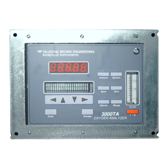
Introduction 1 Front Panel (Operator Interface) The standard 3000TA is housed in a rugged metal case with all controls and displays accessible from the front panel. See Figure 1-1. The front panel has thirteen buttons for operating the analyzer, a digital meter, an alphanu- meric display, and a window for viewing the sample flowmeter. -
Page 10: Recognizing Difference Between Lcd & Vfd
1 Introduction Model 3000TA Data Entry Keys: Six touch-sensitive membrane switches are used to input data to the instrument via the alphanumeric VFD display: • Left & Right Arrows Select between functions currently displayed on the VFD screen. • Up & Down Arrows Increment or decrement values of functions currently displayed. -
Page 11: Rear Panel (Equipment Interface)
Some of those depicted are op- tional and may not appear on your instrument. The connectors are described briefly here and in detail in chapter 3 Installation. Figure 1-2: Model 3000TA Rear Panel • Power Connection Universal AC power source. - Page 12 Note: If you require highly accurate Auto-Cal timing, use external Auto-Cal control where possible. The internal clock in the Model 3000TA is accurate to 2-3 %. Accordingly, internally scheduled calibrations can vary 2-3 % per day. Teledyne Analytical Instruments...
-
Page 13: Operational Theory 2
There is, however, an important difference in the operation of a battery as compared to the Micro-Fuel Cell: In the battery, all reactants are stored within the cell, whereas in the Micro-Fuel Cell, one of the reactants Teledyne Analytical Instruments... -
Page 14: Anatomy Of A Micro-Fuel Cell
2 Operational Theory Model 3000TA (oxygen) comes from outside the device as a constituent of the sample gas being analyzed. The Micro-Fuel Cell is therefore a hybrid between a battery and a true fuel cell. (All of the reactants are stored externally in a true fuel cell.) -
Page 15: Electrochemical Reactions
The electrons released at the surface of the anode flow to the cathode surface when an external electrical path is provided. The current is propor- tional to the amount of oxygen reaching the cathode. It is measured and used to determine the oxygen concentration in the gas mixture. Teledyne Analytical Instruments... -
Page 16: The Effect Of Pressure
2 Operational Theory Model 3000TA The overall reaction for the fuel cell is the SUM of the half reactions above, or: → 2PbO 2Pb + O (These reactions will hold as long as no gaseous components capable of oxidizing lead—such as iodine, bromine, chlorine and fluorine—are present in the sample.) -
Page 17: Sample System
Depending on the mode of operation either sample or calibration gas is delivered. The Model 3000TA sample system is designed and fabricated to ensure that the oxygen concentration of the gas is not altered as it travels through the sample system. - Page 18 Sample In port by teeing to the port with appropriate valves. The shaded portion of the diagram shows the components added when the –C option is ordered. The valving is installed inside the 3000TA-C enclo- sure and is regulated by the instruments internal electronics.
-
Page 19: Electronics And Signal Processing
Figure 2-5: Flow Diagram Electronics and Signal Processing The Model 3000TA Trace Oxygen Analyzer uses an 8031 microcon- troller with 32 kB of RAM and 128 kB of ROM to control all signal pro- cessing, input/output, and display functions for the analyzer. System power is supplied from a universal power supply module designed to be compat- ible with any international power source. - Page 20 These boards are acces- sible after removing the back panel. Figure 2-7 is a block diagram of the Analyzer electronics. Figure 2-7: Block Diagram of the Model 3000TA Electronics Teledyne Analytical Instruments...
- Page 21 4-20 mA dc and the 0-1 V dc analog concentration signal outputs, and the analog range ID outputs. Signals from the power supply are also monitored, and through the microprocessor, the system failure alarm is activated if a malfunction is detected. Teledyne Analytical Instruments...
- Page 22 2 Operational Theory Model 3000TA Teledyne Analytical Instruments 2-10...
-
Page 23: Installation
Immediately report any damage to the shipping agent. Mounting the Analyzer The Model 3000TA is for indoor use in a general purpose area. It is NOT for hazardous environments of any type. The standard model is designed for flush panel mounting. Figure 3-1 is an illustration of the 3000TA standard front panel and mounting bezel. -
Page 24: Rear Panel Connections
Figure 3-2: Required Front Door Clearance Rear Panel Connections Figure 3-3 shows the Model 3000TA rear panel. There are ports for gas inlet and outlet, power, communication, and both digital and analog concen- tration output. The Zero In and Span In ports are not included on the stan- dard model, but are available as options. -
Page 25: Gas Connections
Trace Oxygen Analyzer Installation 3 Figure 3-3: Rear Panel of the Model 3000TA 3.3.1 Gas Connections Before using this instrument, it should be determined if the unit will be used for pressurized service or vacuum service and low pressure applica- tions. -
Page 26: Electrical Connections
3 Installation Model 3000TA The unit is manufactured with inch tube fittings, and 6 mm adapters are supplied for metric system installations. For a safe connection: 1. Insert the tube into the tube fitting, and finger-tighten the nut until the tubing cannot be rotated freely, by hand, in the fitting. (This may require an additional 1/8 turn beyond finger-tight.) - Page 27 (Full scale = 100% of programmable range.) 4–20 mA dc Range ID: 8 mA = Low Range, 12 mA = Medium Range, 16 mA = High Range, 20 mA = Air Cal Range. Figure 3-4: Analog Output Connections Teledyne Analytical Instruments...
- Page 28 3 Installation Model 3000TA Alarm Relays: The three alarm-circuit connectors are spring terminals for making connections to internal alarm relay contacts. Each provides a set of Form C contacts for each type of alarm. Each has both normally open and normally closed contact connections.
- Page 29 (See Remote Calibration Protocol below.) Remote Calibration Protocol: To properly time the Digital Remote Cal Inputs to the Model 3000TA Analyzer, the customer's controller must monitor the Cal Relay Contact. When the contact is OPEN, the analyzer is analyzing, the Remote Cal Inputs are being polled, and a zero or span command can be sent.
- Page 30 Toggling input. Stops/Starts any status message output from the RS-232, until st<enter> is sent again. The RS-232 protocol allows some flexibility in its implementation. Table 3-2 lists certain RS-232 values that are required by the 3000TA implementation. Teledyne Analytical Instruments...
-
Page 31: Remote Probe Connector
Message Interval 2 seconds 3.3.3 Remote Probe Connector The 3000TA is a single-chassis instrument, which has no Remote Probe Unit. Instead, the Remote Probe connector is used as another method for controlling external sample/zero/span gas valves. See Figure 3-6. Figure 3-6: Remote Probe Connector Pinouts The voltage from these outputs is nominally 0 V for the OFF and 15 V dc for the ON conditions. -
Page 32: Installing The Micro-Fuel Cell
3 Installation Model 3000TA Figure 3-7: FET Series Resistance Installing the Micro-Fuel Cell The Micro-Fuel Cell is not installed in the cell block when the instrument is shipped. Install it before the analyzer is placed in service. Once it is expended, or if the cell is exposed to air for too long, the Micro-Fuel Cell will need to be replaced. -
Page 33: Operation
• Set alarm setpoints, and modes of alarm operation (latching, failsafe, etc). Before you configure your 3000TA these default values are in effect: Ranges: LO = 100 ppm, MED = 1000 ppm, HI = 10,000 ppm. Auto Ranging: ON Alarm Relays: Defeated, 1000 ppm, HI, Not failsafe, Not latching. -
Page 34: Using The Data Entry And Function Buttons
4 Operation Model 3000TA Using the Data Entry and Function Buttons Data Entry Buttons: The < > arrow buttons select options from the menu currently being displayed on the VFD screen. The selected option blinks. When the selected option includes a modifiable item, the Δ Δ Δ Δ Δ ∇ arrow buttons can be used to increment or decrement that modifiable item. -
Page 35: The System Function
Once a unique password is assigned and activated, the operator MUST enter the UNIQUE password to gain access to set-up functions which alter the instrument's operation, such as setting the instrument span or zero setting, adjusting the alarm setpoints, or defining analysis ranges. Teledyne Analytical Instruments... -
Page 36: Readings During Calibration
4 Operation Model 3000TA After a password is assigned, the operator must log out to activate it. Until then, anyone can continue to operate the instrument without entering the new password. Only one password can be defined. Before a unique password is assigned, the system assigns TETAI by default. -
Page 37: Setting Up An Auto-Cal
Note: If you require highly accurate Auto-Cal timing, use external Auto-Cal control where possible. The internal clock in the Model 3000TA is acurate to 2-3 %. Accordingly, internally scheduled calibrations can vary 2-3 % per day. -
Page 38: Password Protection
4 Operation Model 3000TA , and press Enter. A new screen for Use < > arrows to blink Auto—Cal Span/Zero set appears. Span OFF Nxt: 0d 0h Zero OFF Nxt: 0d 0h Press < > arrows to blink ), then press Enter again. (You... -
Page 39: Installing Or Changing The Password
Installing or Changing the Password If you want to install a password, or change an existing password, proceed as above in Entering the Password. When you are given the oppor- tunity to change the password: Change Password? <ENT>=Yes <ESC>=No Teledyne Analytical Instruments... - Page 40 4 Operation Model 3000TA Press Enter to change the password (either the default TBEAI or the previously assigned password), or press Escape to keep the existing pass- word and move on. If you chose Enter to change the password, the password assignment screen appears.
-
Page 41: Logout
Password Reentered 4.3.5 System Self-Diagnostic Test The Model 3000TA has a built-in self-diagnostic testing routine. Pre- programmed signals are sent through the power supply, output board and sensor circuit. The return signal is analyzed, and at the end of the test the status of each function is displayed on the screen, either as OK or as a number between 1 and 3. -
Page 42: Version Screen
4 Operation Model 3000TA Press the System button to start the System function. TRAK/HLD Auto—Cal PSWD Logout More Use the < > arrow keys to blink More, then press Enter. Version Self—Test Use the < > arrow keys again to move the blinking to the Self–Test function. -
Page 43: The Zero And Span Functions
20.9% (209,000 ppm), the cell can take a long time to recover if the instrument is used for trace oxygen analysis immediately following calibration in air. Connect the calibration gases to the analyzer according to the instruc- tions given in Section 3.4.1, Gas Connections, observing all the prescribed precautions. Teledyne Analytical Instruments 4-11... -
Page 44: Zero Cal
4 Operation Model 3000TA Shut off the gas pressure before connecting it to the analyzer, and be sure to limit the pressure to 40 psig or less when turning it back on. Readjust the gas pressure into the analyzer until the flowrate (as read on the analyzer’s SLPM flowmeter) settles between 0.1 and 2.4 SLPM (ap-... -
Page 45: Manual Mode Zeroing
4.4.1.3 Cell Failure Cell failure in the 3000TA is usually associated with inability to zero the instrument down to a satisfactorily low ppm reading. When this occurs, the 3000TA system alarm trips, and the LCD displays a failure message. -
Page 46: Span Cal
4 Operation Model 3000TA CELL FAIL/ ZERO HIGH Before replacing the cell: a. Check your span gas to make sure it is within specifications. b. Check for leaks downstream from the cell, where oxygen may be leaking into the system. -
Page 47: Manual Mode Spanning
(209000.00 if you are using air). The < > arrows choose the digit, and the Δ∇ arrows choose the value of the digit. Press Enter to enter the span value into the system and begin the span calibration. Teledyne Analytical Instruments 4-15... -
Page 48: Span Failure
Consider this before replacing the cell. The Alarms Function The Model 3000TA is equipped with 2 fully adjustable concentration alarms and a system failure alarm. Each alarm has a relay with a set of form “C" contacts rated for 3 amperes resistive load at 250 V ac. See Figure in... - Page 49 The defeat alarm mode is incorporated into the alarm circuit so that maintenance can be performed under conditions which would normally activate the alarms. The defeat function can also be used to reset a latched alarm. (See procedures, below.) Teledyne Analytical Instruments 4-17...
- Page 50 4 Operation Model 3000TA If you are using password protection, you will need to enter your password to access the alarm functions. Follow the instructions in section 4.3.3 to enter your password. Once you have clearance to proceed, enter the Alarm function.
-
Page 51: The Range Function
Med = 0–1,000 ppm High = 0–10,000 ppm. The Model 3000TA is set at the factory to default to autoranging. In this mode, the microprocessor automatically responds to concentration changes by switching ranges for optimum readout sensitivity. If the current range limits are exceeded, the instrument will automatically shift to the next higher range. -
Page 52: Fixed Range Analysis
4 Operation Model 3000TA Note: The ranges must be increasing from low to high, for example, if range 1 is set as 0–100 ppm and range 2 is set as 0–1,000 ppm, range 3 cannot be set as 0– 500 ppm since it is lower than range 2. -
Page 53: Signal Output
Signal Output The standard Model 3000TA Trace Oxygen Analyzer is equipped with two 0–1 V dc analog output terminals accessible on the back panel (one concentration and one range ID), and two isolated 4–20 mA dc current outputs (one concentration and one range ID). -
Page 54: Teledyne Analytical Instruments
4 Operation Model 3000TA Range Voltage (V) Current (mA) 0.25 0.50 0.75 CAL (0-25%) 1.00 IMPORTANT: In the event of loss of flow through the analyzer, if the vent is vented to a location of high oxygen content, oxygen will... -
Page 55: Maintenance
To have a replacement cell available when it is needed, TAI recom- mends that one spare cell be purchased 9-10 months after commissioning the 3000TA, or shortly before the end of the cell's one year warranty period. CAUTION: Do not stockpile cells. The warranty period starts on the day of shipment. -
Page 56: When To Replace A Cell
The characteristics of the Micro-Fuel Cell show an almost constant output throughout its useful life and then fall off sharply towards zero at the end. Cell failure in the 3000TA is usually characterized inability to zero the instrument down to a satisfactorily low ppm reading. When this occurs, the 3000TA system alarm trips, and the LCD displays a failure message. - Page 57 This releases the cell and cell holder from the block. The cell and holder will fall out in your hand. Lift Up Cell Block Gate Micro-Fuel Cell Cell Adaptor (For B-2 or A-2 series cell) O-Ring Cell Holder Figure 5-1: Removing the Micro-Fuel Teledyne Analytical Instruments...
-
Page 58: Installing A New Micro-Fuel Cell
Model 3000TA 5.2.4 Installing a New Micro-Fuel Cell It is important to minimize the amount of time that a Teledyne Trace Oxy- gen Sensor is exposed to air during the installation process. The quicker the sensor can be installed into the unit, the faster your TAI O... -
Page 59: Cell Warranty
Maintenance 5 5.2.5 Cell Warranty The Class L-2 Micro-Fuel cell is used in the Model 3000TA. This cell is a long life cell and is warranted for 1 year from the date of shipment. Note any Addenda attached to the front of this manual for special information applying to your instrument. -
Page 60: System Self Diagnostic Test
5 Maintenance Model 3000TA 2. To change between American and European fuses, remove the single retaining screw, flip Fuse Block over 180 degrees, and replace screw. 3. Replace fuse as shown in Figure 5-3. 4. Reassemble Housing as shown in Figure 5-2. -
Page 61: Major Internal Components
The gas piping is illustrated in Figure 2-4, and the major electronic components locations are shown in Figure 2-5, in chapter 2. WARNING: SEE WARNINGS ON THE TITLE PAGE OF THIS MANUAL. The 3000TA contains the following major components: • Analysis Section Micro Fuel Cell (L-2) -
Page 62: Cleaning
5 Maintenance Model 3000TA Cleaning If instrument is unmounted at time of cleaning, disconnect the instru- ment from the power source. Close and latch the front-panel access door. Clean outside surfaces with a soft cloth dampened slightly with plain clean water. - Page 63 • Relay rack mount. Contains either one or two instruments in one 19" relay rack mountable plate (Optional). Sensor: Teledyne L-2 trace analysis Micro-Fuel Cell. Cell Block: 316 stainless steel. Sample System: All wetted parts of 316 stailess steel. 90 % Response Time: 65 seconds at 25 °C (77 °F).
- Page 64 Appendix Model 3000TA Accuracy: ±2% of full scale at constant temperature. ±5% of full scale over operating temperature range, except 0-10 ppm analysis range, once thermal equilibrium is reached. ±1 ppm on 0-10 ppm analysis range, once thermal equilibrium is reached.
-
Page 65: Recommended 2-Year Spare Parts List
Orders for replacement parts should include the part number (if available) and the model and serial number of the instrument for which the parts are intended. Orders should be sent to: Teledyne Analytical Instruments 16830 Chestnut Street City of Industry, CA 91749-1580 Phone (626) 934-1500, Fax (626) 934-1500... -
Page 66: Drawing List
D-62928 Final Assembly/Outline Drawing A-4 19-inch Relay Rack Panel Mount Figure A-1: Single and Dual 19" Rack Mounts NOTE: The MSDS on this material is available upon request through the Teledyne Environmental, Health and Safety Coordinator. Contact at (626) 934-1592 Teledyne Analytical Instruments... -
Page 67: Application Notes On Restrictors, Pressures And Flow
The first function is to limit the flow rate of the sample through the analyzer. A restrictor is chosen to operate over a range of pressures and provide a useable flow rate over that range. Teledyne Analytical Instruments... - Page 68 ( off scale of flow-meter), pressure drops other than the restriction device could become significant , and result in pressurizing the cell. Example 2, A 3000TA is configured for vacuum service as follows. The un-marked restrictor is placed in the sample vent port. The down stream end of the restrictor is then connected to a vacuum pump and by-pass valve.
- Page 69 Operation without a restrictor device is not recommend as mentioned above. A 3000TA without any flow restrictor device was tested on 11-19-97. This results in a flow rate of 2.4 SLPM @ 1 PSIG. This is a cv of 0.023 for the standard sample sys.
- Page 70 Appendix Model 3000TA Teledyne Analytical Instruments...
-
Page 71: Material Safety Data Sheet
Product Name: Micro-Fuel Cells and Super Cells, all classes except A-2C, A-3, and A-5. Electrochemical Oxygen Sensors, all classes except R-19. Mini-Micro-Fuel Cells, all classes. Manufacturer: Teledyne Electronic Technologies/Analytical Instruments Address: 16830 Chestnut Street, City of Industry, CA 91749 Phone: (626) 934-1500... - Page 72 Appendix Model 3000TA Section IV – Fire and Explosion Hazard Data Flash Point: Flammable Limits: LEL: UEL: Extinguishing Media: Use extinguishing media appropriate to surrounding fire conditions. No specific agents recommended. Special Fire Fighting Wear NIOSH/OSHA approved self-contained breathing Equipment: apparatus and protective clothing to prevent contact with skin and eyes.
- Page 73 If there is liquid around the cell while in the instrument, wear eye and hand protection. Cleanup Procedures: Wipe down the area several times with a wet paper towel. Use a fresh towel each time. Contaminated paper towels are considered hazardous waste. Teledyne Analytical Instruments A-11...
- Page 74 NOTE: The above information is believed to be correct and is offered for your information, consideration, and investigation. It should be used as a guide. Teledyne Brown Engineering Analytical Instruments shall not be held liable for any damage resulting from handling or from contact with the above product.
-
Page 75: Teledyne Analytical Instruments
Trace Oxygen Analyzer Appendix Teledyne Analytical Instruments A-13...