Advertisement
Quick Links
www.nordictrack.com
Model No. 831.21873.0
Serial No.
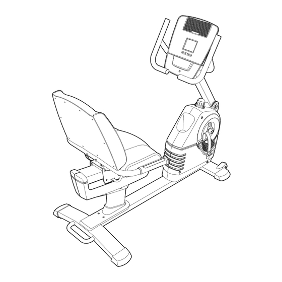
Write the serial number in the
space above for future reference.
Serial Number
Decal
QUESTIONS?
As a manufacturer, we are commit-
ted to providing complete customer
satisfaction.
If you have questions,
or if parts are missing, DO NOT
CONTACT THE STORE; please
contact Customer Care.
IMPORTANT: You must note the
product model number and serial
number (see the drawing above)
before contacting us:
CALL TOLL-FREE:
1-888-825-2588
Mon.-Fri.,
6 a.m.-6 p.m. MT
Sat. 8 a.m.-4 p.m. MT
ON THE WEB:
www.nordictrackservice.com
_®
USER'S MANUAL
Advertisement

Related Manuals for NordicTrack C3SI 831.21873.0


Summary of Contents for NordicTrack C3SI 831.21873.0
- Page 1 _® www.nordictrack.com Model No. 831.21873.0 Serial No. USER'S MANUAL Write the serial number in the space above for future reference. Serial Number Decal QUESTIONS? As a manufacturer, we are commit- ted to providing complete customer satisfaction. If you have questions, or if parts are missing, DO NOT CONTACT THE STORE;...
- Page 2 • Do not allow children on or around machine. • User weight must not exceed 300 pounds. • Replace Jabel if damaged, iflegible, or _ removed. NordicTrack is a registered trademark of ICON IP, Inc.
- Page 3 IMPORTANT PRECAUTIONS WARNING: To reduce the risk of serious injury, read all important precautions and instructions in this manual and all warnings on your exercise cycle before using your exercise cycle. ICON assumes no responsibility for personal injury or property damage sustained by or through the use of this product.
- Page 4 BEFORE YOU BEGIN Congratulations for selecting the new NordicTrack ®C3 after reading this manual, please see the front cover Sl exercise cycle. Cycling is one of the most effective of this manual. To help us assist you, note the product...
- Page 5 ASSEMBLY Assembly requires two persons. Place all parts of the exercise cycle in a cleared area and remove the pack- ing materials. Do not dispose of the packing materials until assembly is completed. In addition to the included tool(s), assembly requires a Phillips screwdriver (_====o and an adjustable wrench _:_.
- Page 6 Orient the Right Front Stabilizer (40) with the Wheel (17) positioned as shown. Attach the Right Front Stabilizer (40) to the right side of the Frame (1) with three M8 x 16mm Patch Screws (54) and three M8 Split Washers (55).
- Page 7 While another person holds the Upright (2) near the Frame (1), locate the wire tie in the Upright. See the inset drawing. Tie the lower end of Wire Tie the wire tie to Pulse Extension Wire (79) and to the Main Wire Harness (43). Next, pull the other end of the wire tie upward out of the top of the Upright (2).
- Page 8 The Console (4) can use four 1.5V D batteries (not included); alkaline batteries are recom- mended. IMPORTANT: If the Console Battery Cover been exposed to cold temperatures, allow it to warm to room temperature before insert- ing batteries. Otherwise, you may damage Screw_ the console displays...
- Page 9 Identify and orient the Seat Handlebar (11) so that the contacts on the Pulse Grips (10) face upward. Make sure that the hexagonal holes are in the indicated locations. Hexagonal Tip: Avoid pinching the Pulse Wire (58). Holes Attach the Seat Handlebar (11) to the Seat Carriage (3) with two M10 x 32mm Button Bolts (78) and two M10 Locknuts (64).
- Page 10 Attach the Seat (9) to the Seat Carriage (3) with four M6 x 38mm Patch Screws (81) and four M6 Washers (44) (only two of each are shown). Note: The Patch Screws and Washers may be preattached to the underside of the Seat. 10.
- Page 11 11. Identify the Right Pedal (21), which is marked with an "R." Using an adjustable wrench, firmly tighten the Right Pedal clockwise into the Right Crank (23). Strap Tighten the Left Pedal (not shown) counter- clockwise into the Left Crank (not shown). IMPORTANT: Tighten both Pedals as firmly as possible.
- Page 12 HOW TO USE THE EXERCISE CYCLE HOW TO ADJUST THE PEDAL STRAPS HOW TO ADJUST THE UPRIGHT To adjust the pedal The upright can be straps, first pull the adjusted to the posi- tion that is the most ends of the straps off the tabs on the comfortable for you.
- Page 13 CONSOLE DIAGRAM I tEART RAIE 2 F1,F'! TIME ENDURANCE ODOMETER HEART IRATE 3 2.54 ,Su DISTANCE SPEED RESET PERFORMANCE HEART RATE , ----- d)fntv A) TRAINER HEART RATE WORKOUTS WORKOUTS WORKOUTS iFIT, SILENT MAGNETIC RESISTANCE PRIORITY DISPLAY FEATURES OF THE CONSOLE The console features the iFit Interactive Workout System, which enables the console to accept iFit The revolutionary console offers an array of features...
- Page 14 The°werr HOW TO USE THE MANUAL MODE display--The lower !',,,_ Begin pedaling or press any button on the right display can TiME console to turn on the console. show the your ped- _,2B DISTANCE SPEED aling speed (in miles or kilometers A moment after you begin pedaling or press a but- ton, a tone will sound, and the display will light.
- Page 15 Measure your heart rate if desired. When your pulse is detected, a flashing You can measure you heart rate using either the heart symbol will handgrip pulse sensor or an optional chest pulse appear in the dis- J'JI DISTANCE I C LI sensor (see page 20 for information about the play, and then your heart rate will...
- Page 16 HOW TO USE A TRAINER WORKOUT ment of the workout. The height of the flashing segment indicates the resistance level for the cur- Begin pedaling or press any button on the rent segment. At the end of each segment of the console to turn on the console.
- Page 17 HOW TO USE A HEART RATE WORKOUT During a heart rate workout, the console will regu- larly compare your heart rate to the target heart Begin pedaling or press any button on the rate for the current segment of the workout. If your console to turn on the console.
- Page 18 HOW TO USE AN IFIT WORKOUT HOW TO USE THE SOUND SYSTEM Begin pedaling or press any button on the To play music or audio books through the console's console to turn on the console. sound system while you exercise, plug an audio cable (not included) into the jack on the console and into a A moment after you begin pedaling or press a but- jack on your MP3 player or CD player;...
- Page 19 HOW TO CHANGE CONSOLE SETTINGS Select a unit of measurement if desired. The console features a user mode that allows you to The console can show pedaling pace and distance in either miles or kilometers. select a unit of measurement and a backlight option for the console and to view console usage information.
- Page 20 THE OPTIONAL CHEST PULSE SENSOR INSTALLING THE RECEIVER FOR THE OPTIONAL CHEST PULSE SENSOR The optional chest pulse sensor provides hands-free operation and continuously monitors your heart rate If you purchase the optional chest pulse sensor, follow during your workouts. To purchase the optional the steps below to install the receiver included with the chest pulse sensor, see the front cover of this...
- Page 21 MAINTENANCE AND TROUBLESHOOTING HOW TO ADJUST THE REED SWITCH Inspect and tighten all parts of the exercise cycle reg- ularly. Replace any worn parts immediately. If the console does not display correct feedback, the To clean the exercise cycle, use a damp cloth and a reed switch should be adjusted.
- Page 22 HOW TO ADJUST THE BELT Loosen, but do not remove, the three indicated screws (A). Insert the shaft of a screwdriver downward If the pedals slip while you are pedaling, even while between the Idler (B) and the Idler Pulley (38). Pull the the resistance is adjusted to the highest setting, the top of the screwdriver toward the rear of the exercise belt may need to be adjusted.
- Page 23 EXERCISE GUIDELINES Burning Fat--To burn fat effectively, you must exer- cise at a low intensity level for a sustained period of time. During the first few minutes of exercise, your body uses carbohydrate calories for energy. Only after the first few minutes of exercise does your body begin to use stored fat calories for energy.
- Page 24 SUGGESTED STRETCHES The correct form for several basic stretches is shown at the right. Move slowly as you stretch--never bounce. 1. Toe Touch Stretch Stand with your knees bent slightly and slowly bend forward from your hips. Allow your back and shoulders to relax as you reach down toward your toes as far as possible.
- Page 25 PART LIST--Model No. 831.21873.0 Rogo8A Key No. Qty. Description Key No. Qty. Description Frame Reed Switch/Wire Upright Drive Belt Seat Carriage Rear Stabilizer Cap Console Seat Handle Crank Cover Flange Screw Accent Ring M6 x 42mm Patch Screw Upright Knob M8 x 55mm Patch Screw Backrest M6 Locknut...
- Page 26 EXPLODED DRAWING A--Model No. 831.21873.0 Rogo8A...
- Page 27 EXPLODED DRAWING B--Model No. 831.21873.0 Rogo8A ,_I_--37 85--_. 24 2i 30 45...
- Page 28 ORDERING REPLACEMENT PARTS To order replacement parts, please see the front cover of this manual. To help us assist you, be prepared to provide the following information when contacting us: • the model number and serial number of the product (see the front cover of this manual) •...