
Related Manuals for Salus ST320RF


Summary of Contents for Salus ST320RF
- Page 1 ST320RF Manual Version 005:Layout 1 21/10/10 15:32 Page 1 S-Series Digital Thermostat S-Series Digital Thermostat Model No ST320RF Instruction Manual...
- Page 2 ST320RF Manual Version 005:Layout 1 21/10/10 15:32 Page 2 ST320RF INSTRUCTION MANUAL...
-
Page 3: Product Compliance
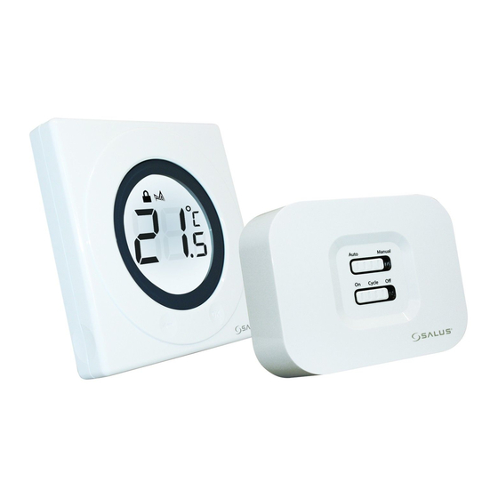
EC Marking directive 93/68/EEC SAFETY INFORMATION These instructions are applicable to the Salus Controls model stated on the front cover of this manual only, and must not be used with any other make or model. These instructions are intended to apply in the United Kingdom only, and should be followed along with any other statutory obligations. - Page 4 The ST320RF from Salus Controls is a stylish and accurate electronic thermostat with a large, easy to read LCD display. The thermostat has been specifically designed to be used Volt Free. Unlike ordinary single unit design thermostats, this is a new type of thermostat separating the operational functions into two units.
-
Page 5: Installation
Installing the ST320RF in enclosed areas such as cellars and basements is not recommended. BOILER RECEIVER COM N/O MAINS FEED Thermostat loop (Remove link) Live Feed ST320RF INSTRUCTION MANUAL... - Page 6 ST320RF, but a parking terminal is provided to connect an Earth wire if one is present. These electrical connections are shown in the table below: Terminal Function Common Contact (volt free input) Normally Open Contact (volt free output) Earth Parking (No electrical connection) Incoming Mains - Live Incoming Mains - Neutral ST320RF INSTRUCTION MANUAL...
-
Page 7: Installing And Replacing Batteries
Ensure that the batteries are inserted correctly, paying careful attention to the polarity markings on the battery and next to the battery holders. After inserting the batteries, refit the ST320RF case and retighten the securing screw. ST320RF INSTRUCTION MANUAL... -
Page 8: On The Receiver
While the signal is being received, the SYNC LED will turn on until the pairing has completed successfully; the SYNC LED will then turn off and the Green Power LED will turn on again. The Control Centre will continue to transmit a pairing signal for 10 minutes before returning to NORMAL mode. ST320RF INSTRUCTION MANUAL... - Page 9 Use the Touch Ring to scroll through the Menus, and press the OK key to select the PAIR menu: You can scroll through the menus in either direction (forwards or backwards) depending on the direction you move your finger around the Touch Ring. The menus are displayed in the order shown in the picture above. ST320RF INSTRUCTION MANUAL...
- Page 10 The unit counts down for a period of 10 minutes, with the RF Signal indicator flashing while the signal is being transmitted. The RF address code will be generated randomly and the Control Centre will transmit the signal every second for the full 10 minutes until: ST320RF INSTRUCTION MANUAL...
- Page 11 Replacing the Control Centre batteries will not affect the RF code setting. Pressing and holding the SYNC button on the Receiver will however clear the RF address code saved into the internal memory, and switch the Receiver into learning mode, as previously described. ST320RF INSTRUCTION MANUAL...
- Page 12 Once the Receiver has established communication successfully, the green Power LED will flash for 4 seconds to indicate the process has completed correctly. It will transmit only when there is a need to control the heating system. ST320RF INSTRUCTION MANUAL...
-
Page 13: Receiver Led Indicators
Receiver is either ready to receive a new RF address code in SYNC mode, flashing or has failed to store the new RF address code when in SYNC mode Yellow Receiver is in Failsafe mode after no RF signal received for over 1 hour ST320RF INSTRUCTION MANUAL... -
Page 14: After Installation
If the Reset Button is pressed, the ST320RF will behave in the same way as described above, except that any previously saved user settings stored in the internal memory will be deleted and overwritten with the default settings. ST320RF INSTRUCTION MANUAL... - Page 15 Indicates the unit is transmitting a wireless signal Touch Lock indicator Indicates touch lock is activated Heat Mode indicator Indicates heating output is turned on. Frost Mode indicator Indicates frost setting is turned on Battery Status Indicates battery is low ST320RF INSTRUCTION MANUAL...
- Page 16 Single touch- sets the unit back 1 step. Hold for 2 seconds sets unit back to normal mode Reset Button Resets the thermostat to default (original factory) settings Slide Switch Activates and deactivates the key lock function (prevents accidental changes) ST320RF INSTRUCTION MANUAL...
- Page 17 Switches Receiver output on and off in a 15 minute cycle (4 minutes on, 11 minutes off) Means the relay output is always off SYNC Button Enables RF signal synchronisation with ST320RF Control Centre Reset Button Resets the Receiver to default (original factory) settings ST320RF INSTRUCTION MANUAL...
-
Page 18: Operation
This will display the current set temperature. The set temperature will be displayed for two seconds before the LCD changes to display the room temperature again. ST320RF INSTRUCTION MANUAL... -
Page 19: Changing The Set Temperature
The ST320RF will go back to NORMAL mode without changing the set temperature after 10 seconds of inactivity, or after pressing the Arrow key. If the ST320RF is in FROST mode, the set temperature cannot be adjusted. Turn off FROST mode as described below to allow the set temperature to be changed. ST320RF INSTRUCTION MANUAL... -
Page 20: Accessing The Menus
Pressing the Arrow key will return the ST320RF to NORMAL mode. The thermostat will also return to NORMAL mode after 10 seconds if no Key is pressed or if no movement is detected on the Touch Ring. ST320RF INSTRUCTION MANUAL... - Page 21 FROST menu screens. On entering the menu, use the Touch Ring to scroll to the preferred option (OFF or ON), and confirm the choice using the OK button. Use the Arrow key to return to the Menu Option display. ST320RF INSTRUCTION MANUAL...
-
Page 22: Sleep Menu
(ON/OFF or PWM control), and confirm the choice using the OK button. Use the Arrow key to return to the Menu Option display. PWM mode should only be selected by the Engineer carrying out the installation or other qualified person. ST320RF INSTRUCTION MANUAL... -
Page 23: Off Mode
ST320RF batteries as soon as possible to restore normal operation. If the voltage of the replaced batteries is not high enough (if older batteries have been used) the unit will remain in OFF mode and will not reset. ST320RF INSTRUCTION MANUAL... -
Page 24: Slide Switch
The Reset Button is provided as a way to restore the thermostat to its default factory settings. Pressing this button will delete any previously entered settings. a.The set temperature is 18°C. b.Frost:Off c:Sleep:Off d.Control method: On/Off. e: RF address code:00000000000000000000 (20bits). ST320RF INSTRUCTION MANUAL... -
Page 25: Receiver Modes
With the Failsafe switch in the ON position, the output relay will be turned on, in the OFF position the output relay will be turned off, and in the CYCLE position the output relay will be operated according to a preset time sequence (on for 4 minutes and off for 11 minutes). ST320RF INSTRUCTION MANUAL... - Page 26 To illustrate this point, even when switched into Manual Mode the Receiver can still receive the RF signal from the Control Centre and once the user switches to Auto Mode, the output relay will be controlled to turn on or turn off automatically once more. ST320RF INSTRUCTION MANUAL...
-
Page 27: Maintenance
(please DO NOT use solvents, polishes, detergents or abrasive cleaners, as these can damage the thermostat). There are no user serviceable parts within the unit; any servicing or repairs should only be carried out by Salus Controls or their appointed agents. Should the ST320RF thermostat fail to function correctly, check: •... -
Page 28: Product Specification
Display Resolution: 0.5 ºC Set Temperature Range: 5.0 ºC to + 35 ºC Resolution: 0.5 ºC Control Control Method: 1. On – Off control 2. PWM control Memory Backup Type: Electrically Erasable Programmable Read Only Memory (EEPROM) ST320RF INSTRUCTION MANUAL... - Page 29 Radio Frequency (RF) Settings Operating Frequency: 868 MHz Max. Operating Range: 100 metres (free air) 30 metres (indoors) Protection rating: IP30 Environment Operating Temperature: 0 ºC to + 50 ºC Storage Temperature: - 10 ºC to + 60 ºC ST320RF INSTRUCTION MANUAL...
- Page 30 ST320RF Manual Version 005:Layout 1 21/10/10 15:32 Page 30 ST320RF INSTRUCTION MANUAL...
- Page 31 Salus Controls warrants that this product will be free from any defect in materials or workmanship, and shall perform in accordance with its specification, for a period of two years from the date of purchase. Salus Controls sole liability for breach of this warranty will be (at its option) to repair or replace the defective product.
- Page 32 ST320RF Manual Version 005:Layout 1 21/10/10 15:32 Page 32 salus-tech. Email: sales@salus-tech.com Tel: 01226 323961 Sales Email: tech@salus-tech.com Tel: 01226 323961 Technical Salus Controls plc, Salus House, Dodworth Business Park South, Whinby Road, Dodworth, Barnsley S75 3SP...