
Related Manuals for Salus ST620VBC


Summary of Contents for Salus ST620VBC
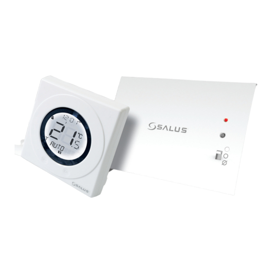
- Page 1 Programmable Thermostat with Plug in RF Boiler Control Instruction Manual Model No ST620VBC...
- Page 2 ST620VBC INSTRUCTION MANUAL...
- Page 3 R&TTE Directives 99/5/EC SAFETY INFORMATION These instructions are applicable to the Salus Controls model stated on the front cover of this manual only, and must not be used with any other make or model. These instructions are intended to apply in the United Kingdom only, and should be followed along with any other statutory obligations.
- Page 4 INTRODUCTION The ST620VBC comprises of the S series programmable room thermostat with an integral plug- in RF boiler control. The RF boiler control is a direct replacement for the basic time clock or blanking plate usually supplied with the boiler. Installing the RF boiler control takes minutes.
- Page 5 Installation Manual 3. USER CONTROLS Warranty card, 4. BASIC OPERATION Surface mount stand 5. ADVANCED FUNCTIONS 2 x Screws 6. SERVICE FUNCTIONS 2 x Anchors 7. USEFUL INFORMATION 2 x AA batteries 8. TECHNICAL SPECIFICATION 9. WARRANTY ST620VBC INSTRUCTION MANUAL...
-
Page 6: Getting Started
You will now see the battery compartments on the rear of the front fascia as shown. Ensure that the batteries are inserted correctly and check the polarity. ST620VBC INSTRUCTION MANUAL... - Page 7 Now put the ST620 front fascia in a safe place so you can mount the ST620 back plate. The back plate is easily fixed to the wall and uses industry standard mounting positions. We recommend that you continue with the back plate mounting before starting to program the ST620. ST620VBC INSTRUCTION MANUAL...
- Page 8 Mounting the Back plate Use the screws and anchors supplied to mount the ST620 back plate in your chosen position. Now attach the ST620 front fascia to the back plate. Remember to tighten the securing screw ST620VBC INSTRUCTION MANUAL...
- Page 9 Follow electro static discharge precaution. Do not touch any visible PCB parts or components. Switch off the boiler at its main supply. Remove cover panel or existing control. Insert the integral boiler control ensuring correct location of the rear Connection pins. ST620VBC INSTRUCTION MANUAL...
- Page 10 OFF position. To ensure the boiler control is connected properly, please now move the switch to ON The boiler should now go on and the LED on the your boiler control should illuminate ST620VBC INSTRUCTION MANUAL...
- Page 11 If you find that the LED on the integral boiler control and the boiler are already on, double check you have the integral boiler controls selector switch in the AUTO position. If the switch is in the AUTO position follow the instructions above but decrease the temperature to 5 º C. The LED and boiler should go off. ST620VBC INSTRUCTION MANUAL...
- Page 12 After 3 seconds the Boiler Control LED will flash once every second to indicate it is ready to pair and ready to receive a signal from the ST620. The Boiler Control will remain in pairing mode for 12 minutes. ST620VBC INSTRUCTION MANUAL...
- Page 13 Use the Touch Ring to scroll through the Menus to locate the pair option then press OK key Press OK key again activate pairing mode. PAIR will stop flashing and the pair icon will appear The display will change to show a rundown timer: ST620VBC INSTRUCTION MANUAL...
-
Page 14: Additional Information
SYNC button on the Boiler Control will however clear the RF address code saved into the internal memory, and switch the Boiler Control into pairing mode, as previously described. SERVICE and CONTROL functions If you require to use the above functions of the ST620 during this Installation, please refer to pages 33 and 34. ST620VBC INSTRUCTION MANUAL... - Page 15 The status and operation of the ST620 is clearly shown on the large Liquid Crystal Display (LCD). This display allows the user to see at a glance the current status of the heating system, as well as a clear indication of the current room temperature. ST620VBC INSTRUCTION MANUAL...
- Page 16 RCC indicator Indicates unit is searching for radio controlled clock signal Service indicator Indicates Service function is active Frost Mode indicator Indicates frost setting is turned on Touch Lock indicator Indicates touch lock is activated ST620VBC INSTRUCTION MANUAL...
- Page 17 Single touch- sets the unit back 1 step. Hold for 2 seconds sets unit back to normal mode Reset Button Resets the thermostat to default (original factory) settings Slide Switch Activates and deactivates the key lock function (prevents accidental changes) ST620VBC INSTRUCTION MANUAL...
- Page 18 LCD changes to display the room temperature again. The ST620 will go back to AUTO mode without changing the set temperature after 10 seconds of inactivity, or after pressing the Arrow key. ST620VBC INSTRUCTION MANUAL...
-
Page 19: Manual Override
Manual Override mode is cancelled. Manual Override mode can be cancelled at any time by pressing and holding the Arrow key for 2 seconds – this will return the ST620 to AUTO mode. ST620VBC INSTRUCTION MANUAL... - Page 20 The user can also move the switch to the OFF position; when in this mode, the boiler will not receive a signal from the ST620 and the LED indicator will also be lit constantly. ST620VBC INSTRUCTION MANUAL...
- Page 21 AUTO/MANUAL mode after 10 seconds if no Key is pressed. NOTE: SERVICE and CONTROL are functions that should be carried out by an installer or competent person. These function are explained in detail on Page 33. ST620VBC INSTRUCTION MANUAL...
- Page 22 After correct selection of the day option, the ST620 display will change to the next programming screen. These screens allow you to set the required time and temperature settings to provide optimum control for your heating system. ST620VBC INSTRUCTION MANUAL...
- Page 23 Programme 1 (hour, minutes, and temperature). If you decide to enter settings for individual days rather than Weekdays or Weekends, the ST620 also offers a time saving COPY function that allows the user to copy settings from one day to another. ST620VBC INSTRUCTION MANUAL...
-
Page 24: Holiday Function
ST620 is in HOLIDAY mode the FROST protection mode will be disabled. When the holiday end date is reached, the HOLIDAY mode will be turned off automatically and the ST620 will operate in AUTO mode. The HOLIDAY mode indicator will be displayed on all the HOLIDAY menu screens. ST620VBC INSTRUCTION MANUAL... - Page 25 (‘S_YEAR’) – this is done in exactly the same way as previously described for the date and month. After confirming the year setting by pressing the OK key, the display will then change to display the first screen for entering the holiday end date. ST620VBC INSTRUCTION MANUAL...
- Page 26 MANUAL or AUTO indication. Pressing the Touch Ring will change the display to show the current temperature setting, but this setting cannot be adjusted while in this mode. ST620VBC INSTRUCTION MANUAL...
- Page 27 Entering the FROST menu allows you to turn the frost protection mode of the ST620 on or off. The FROST mode temperature is preset at 5 ºC; this temperature is factory set and cannot be adjusted. The FROST mode indicator will be displayed on all the FROST menu screens. ST620VBC INSTRUCTION MANUAL...
- Page 28 Pressing the Touch Ring for 1 second will turn on the LCD backlight, and pressing the Touch Ring for 3 seconds will wake the ST620 from SLEEP mode and restore the programmable thermostat to AUTO mode. NOTE: The unit will not control the heating while in SLEEP mode. ST620VBC INSTRUCTION MANUAL...
- Page 29 If the time and date setting need to be set manually, this can be done by accessing the TIME menu. The first option within the menu is a choice of 12 or 24 hour clock setting. ST620VBC INSTRUCTION MANUAL...
- Page 30 – change this setting in the same way using the Touch Ring, and confirm the setting using the OK button. After setting the time, the next screen display allows you to set the date – this is set in exactly the same way as previously described for the time. ST620VBC INSTRUCTION MANUAL...
- Page 31 This is explained on page 7. However if you require to change the language of the ST620 then you can do this by accessing the language menu. Entering the language menu will allow you select your required language ST620VBC INSTRUCTION MANUAL...
- Page 32 Once you have displayed your required language, press the OK button to select and save. ST620VBC INSTRUCTION MANUAL...
- Page 33 SERVICE menu screens. Firstly you need to enter a unique PIN code, when the first digit flashes scroll to set the first digit and press OK to confirm the repeat for the other two digits. ST620VBC INSTRUCTION MANUAL...
- Page 34 Once all digits have been entered, press OK to confirm or the arrow key to return to previous digit or previous display. The service code is total 3 digits, from 000 to 999. NOTE: If you forget the code then you will need to contact the Salus Technical Team Now you have entered your own PIN code you will be asked to select SERVICE ON or OFF.
- Page 35 If you have selected service as ON then follow the instructions on the next pages. The next menu screen allows you to set the next service date for the system. Set the date in the order of; day, month and year: ST620VBC INSTRUCTION MANUAL...
- Page 36 Once set as described, the SERVICE indicator will appear on the display 30 days before the set date. At seven days before the set date, the SERVICE indicator will flash and the bottom section of the display will alternate between displaying the current mode (AUTO or MANUAL), and the telephone number previously entered. ST620VBC INSTRUCTION MANUAL...
- Page 37 ST620VBC INSTRUCTION MANUAL...
- Page 38 (ON/OFF or PWM control), and confirm the choice using the OK button. Use the Arrow key to return to the Menu Option display. PWM mode should only be selected by the Engineer carrying out the installation or other qualified person. ST620VBC INSTRUCTION MANUAL...
- Page 39 Clock, Programme or Temporary Override modes – in this case, the backlight will remain illuminated for 10 seconds after the last key press. The backlight will not illuminate if the ST620 battery is low, or if the Slide Switch is in the LOCKED position. ST620VBC INSTRUCTION MANUAL...
- Page 40 Boiler Control will turn off the boiler, and the LED indicator will flash constantly (two times every second). Once the Boiler Control receives a valid ON or OFF signal, the Boiler Control will control the heating system accordingly. ST620VBC INSTRUCTION MANUAL...
-
Page 41: Technical Specification
(please DO NOT use solvents, polishes, detergents or abrasive cleaners, as these can damage the thermostat). There are no user serviceable parts within the unit; any servicing or repairs should only be carried out by Salus Controls or their appointed agents. - Page 42 Radio Frequency (RF) Settings Operating Frequency: 868 MHz Max. Operating Range: 100 metres (free air) or 30 metres (indoors) Environment Operating Temperature: 0 ºC to + 50 ºC Storage Temperature: - 10 ºC to + 60 ºC ST620VBC INSTRUCTION MANUAL...
- Page 43 Salus Controls warrants that this product will be free from any defect in materials or workmanship, and shall perform in accordance with its specification, for a period of two years from the date of installation. Salus Controls sole liability for breach of this warranty will be (at its option) to repair or replace the defective product.
- Page 44 Email: sales@salus-tech.com Tel: 01226 323961 Sales Email: tech@salus-tech.com Tel: 01226 323961 Technical...