
Related Manuals for Salus SOLO ST920WF


Summary of Contents for Salus SOLO ST920WF
- Page 1 ST920WF SOLO 3H/2C Wi-Fi Thermostat Installation Manual www.salusinc.com For other language versions, please visit:...
- Page 2 Regulatory Statements This device complies with Part 15 of the FCC Rules. Operation is subject to the following two conditions: (1) this device may not cause harmful interference, and (2) this device must accept any interference received, including interference that may cause undesired operation. Changes or modifications to this unit not expressly approved by the party responsible for compliance could void the user’s authority to operate the equipment.
-
Page 3: Safety Instructions
Safety Instructions Please read these instructions carefully BEFORE INSTALLING AND USING the ST920WF Thermostat. This manual is meant to be used as a reference guide for the installation, configuration and maintenance of your device. • Follow all regulations required by the local jurisdiction and electricity supplier regarding the installation or replacement of a thermostat. -
Page 4: Using This Manual
Using this Manual For the latest Instructions go to: WWW.SALUSINC.COM Special Attention Boxes This manual uses special attention icons to alert the reader of important safety concerns, information important to reliable operation of the controls or helpful installation/setup information. Safety: Indicates a condition which may cause severe personal injury, death or major property damage Important Information:... -
Page 5: Table Of Contents
SALUS WARRANTY ........ -
Page 6: In The Box
In The Box ST920WF Thermostat Wall Plate (if required) with Mounting Plate Mounting Screws & Anchors Installation Manual... -
Page 7: Installing The Thermostat
Installing the Thermostat Tools You may need the following tools to There are five steps to installing install the ST920WF Thermostat: the thermostat: • #1 Phillips or flathead screwdriver 1. Determine Wiring Configuration • Power drill with 3/16” bit (if new 2. -
Page 8: Determine Wiring Configuration
Determine Wiring Configuration If the ST920WF Thermostat is being installed in a new system or if wiring changes are intended, refer to Appendix A for the wiring configurations and skip to Install Mounting Plate. When replacing a thermostat and replicating the wiring of the existing thermostat is desired on the ST920WF the following applies. - Page 9 Wire Color Record NON-HP Wire Color...
-
Page 10: Remove Old Thermostat
Remove Old Thermostat Remove the old thermostat from the wall, taking care not to allow the wiring to fall inside the wall. Wrap wires around a pencil or similar object to prevent them from falling into the wall void. The ST920WF Thermostat IS NOT COMPATIBLE with supply voltages above 30 VAC. -
Page 11: Install Mounting Plate
Install Mounting Plate (with Wall Plate, if required): Use the included wall anchors and screws to attach the Mounting Plate to the wall, making sure the wires run through the center opening. To cover paint or screw holes on the wall behind the thermostat, insert the Wall Plate between the Mounting Plate and the wall as shown. -
Page 12: Attach Wiring
Attach Wiring: To insert a wire into a terminal, flip up the locking tab and slide the wire into the socket directly above the corresponding label. Insert each wire as required for the desired appliance. Once each wire is inserted, flip the tab down to lock it in position. -
Page 13: Attach Display To Mounting Plate
Attach Display to Mounting Plate: Line up sockets in the back of the thermostat with the posts on the wall plate and snap it into place. Make sure the connector pins are not bent and wires do not interfere with the thermostat engagement. -
Page 14: Turn On Power To Hvac System
Download the SALUS SOLO application on your IOS or Android device. After downloading the application, follow the steps in the SALUS SOLO Mobile Application Guide at: https://www.salusinc.com/downloads/... -
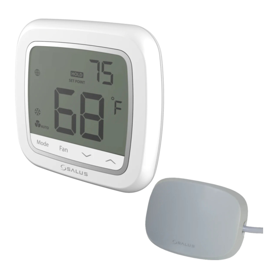
Page 15: Screen Display & Controls
Screen Display & Controls Alphanumeric text display Schedule Override Indicator Fan indicator: Temporary: & Permanent: Auto - On - Setpoint or parameter value Cooling Mode Setpoint indicator Off Mode Auto Cooling/ Schedule running indicator Heating mode Fahrenheit or Celsius units Heating Mode Room Temperature Emergency Heat mode... -
Page 16: Specifications/Troubleshooting
Specifications Temperature units °C or °F 32° to 122°F (0° to 50°C) Operating: 5 to 90% Relative Humidity (non-condensing) Environmental 14° to 140°F (-10° to 60°C) Storage: 5 to 90% Relative Humidity (non-condensing) 802.11 b/g/n, 2.4 GHz band Communications Bluetooth v4.2 BR/EDR and BLE (for Commissioning) 18-30 VAC at RC and C terminals AC power 5 relay outputs rated for 1A @ 18-30 VAC... -
Page 17: Salus Warranty
Salus Warranty SALUS North America, Inc. (“Salus”) warrants that for a period of five (5) years (“Warranty Period”) from the date of purchase by the consumer (“Customer”), this device, excluding batteries (“Product”), shall be free of defects in materials and workmanship under normal use and service in accordance with all supplied instructions. - Page 18 Salus Warranty (continued) No oral or written information or advice given by Salus or a Salus-authorized representative shall modify or extend this warranty. If any term is held to be illegal or unenforceable, the legality or enforceability of the remaining terms shall not be affected or impaired.
-
Page 19: Appendix A - Wiring Diagrams
Appendix A - Wiring Diagrams ST920WF Thermostat Terminal Reference Terminal Non-Heat Pump Heat Pump 24 VAC Power – Cool 24 VAC Power – Heat 24 VAC Common (Use SA918 Wire Extender if C-wire is not available) 1st Stage Cooling 1st Stage Compressor 2nd Stage Cooling 2nd Stage Compressor W1/OB... - Page 20 Conventional Single Transformer Heat and Cool System:...
- Page 21 Conventional Two Transformer Heat and Cool System:...
- Page 22 Single Transformer Heat Pump System:...
- Page 23 This page intentionally left blank.
- Page 24 SALUS NA, Inc. (888) 387-2587 | sales@salusinc.com www.salusinc.com Copyright © SALUS North America, Inc. 2020 SMC-IM-ST920WF-202007v1...