
Related Manuals for Toshiba PROSEC T1-16S


Summary of Contents for Toshiba PROSEC T1-16S
- Page 1 6F3B0253 UM-TS01 -E031 PROGRAMMABLE CONTROLLER T1- 16S PROSEC USER’S MANUAL Basic Hardware and Function TOSHIBA CORPORATION...
- Page 2 Because controlled system applications vary widely, you should satisfy yourself as to the acceptability of this equipment for your intended purpose. In no event will Toshiba Corporation be responsible or liable for either indirect or consequential damage or injury that may result from the use of this equipment.
- Page 3 The contents of the conformity are shown below. Application of EMC : 89/336/EEC (as amended by 91/263/EEC and 92/31/EEC) Council Directive LVD : 72/23/EEC (as amended by 93/68/EEC) Manufacture’s Name Toshiba Corporation, Fuchu Operations-Social Infrastructure Systems Address 1, Toshiba-Cho Fuchu-shi TOKYO 183-8511 Japan declares, that the product...
- Page 4 6F3B0253 UL/c-UL Listing The Programmable Controller PROSEC T1-16S (hereafter called T1-16S) is UL/c-UL listed as shown below. UL and c-UL Listing File Number : E95637 Product Name : Programmable Controller , T1-16S Product Covered : Main Unit TDR116S6S, TDR116S6C, TDR116S3S, TDR116S3C I/O module TDI116M*S, TDD116M*S, TDO116M*S, TAD121M*S, TAD131M*S, TDA121M*S, TDA131M*S,...
-
Page 5: Safety Precautions
1. The T1-16S has been designed and manufactured for use in an industrial environment. However, the T1-16S is not intended to be used for systems which may endanger human life. Consult Toshiba if you intend to use the T1-16S for a special application, such as transportation machines, medical apparatus, aviation and space systems, nuclear controls, submarine systems, etc. - Page 6 5. Turn off power immediately if the T1-16S or related equipment is emitting smoke or odor. Operation under such situation can cause fire or electrical shock. Also unauthorized repairing will cause fire or serious accidents. Do not attempt to repair. Contact Toshiba for repairing. Wiring: CAUTION 1.
- Page 7 6F3B0253 Safety Precautions Operation: WARNING 1. Configure emergency stop and safety interlocking circuits outside the T1-16S. Otherwise, malfunction of the T1-16S can cause injury or serious accidents. CAUTION 2. Operate the T1-16S and the related modules with closing the terminal covers. Keep hands away from terminals while power on, to avoid the risk of electrical shock.
- Page 8 7. Check by referring “Troubleshooting” section of this manual when operating improperly. Contact Toshiba for repairing if the T1-16S or related equipment is failed. Toshiba will not guarantee proper operation nor safety for unauthorized repairing.
- Page 9 Read related manual thoroughly for safety. and stick it near the power terminals Stick this seal on unit or near unit. where it can be readily seen. Take off this sheet before wiring. Contact Toshiba if the label is damaged. Basic Hardware and Function...
-
Page 10: About This Manual
About This Manual About This Manual This manual has been prepared for first-time users of Toshiba’s Programmable Controller T1-16S to enable a full understanding of the configuration of the equipment, and to enable the user to obtain the maximum benefits of the equipment. - Page 11 6F3B0253 About This Manual Terminology The following is a list of abbreviations and acronyms used in this manual. microsecond ASCII American Standard Code For Information Interchange American Wire Gage Block Check Code Counter-Clockwise Central Processing Unit Clockwise EEPROM Electrically Erasable Programmable Read Only Memory hexadecimal (when it appears in front of an alphanumeric string) Input/Output Light Emitting Diode...
-
Page 12: Table Of Contents
6F3B0253 Contents Contents Safety Precautions .................. About This Manual .................. System Configuration ..............Introducing the T1-16S ..............Features ....................System configuration ................I/O expansion ..................Components ..................1.5.1 Basic unit ..................1.5.2 I/O modules ..................1.5.3 Options .................... Programmer port function ..............RS-485 port communication function .......... - Page 13 6F3B0253 Contents Operating System Overview ............Operation modes ................About the built-in EEPROM ..............Scanning ..................... Programming Information ............. Devices and registers ................. Index modification ................Real-time clock/calendar ..............I/O allocation ..................T1-16S memory mode setting.............. User program configuration ..............6.6.1 Main program ..................
- Page 14 6F3B0253 Contents Troubleshooting ................281 10.1 Troubleshooting procedure ..............282 10.1.1 Power supply check ................. 283 10.1.2 CPU check ..................284 10.1.3 Program check ................. 284 10.1.4 Input check ..................285 10.1.5 Output check ..................286 10.1.6 Environmental problem ..............287 10.2 Self-diagnostic items ................
-
Page 15: System Configuration
6F3B0253 Section 1 System Configuration Introducing the T1-16S, 14 Features, 16 System configuration, 19 I/O expansion, 20 Components, 21 Computer link system, 27 T1-16S Communication function, 28 Real-time data link system, 32 Peripheral tools, 33 Basic Hardware and Function... -
Page 16: Introducing The T1-16S
6F3B0253 1. System Configuration 1.1 Introducing the T1-16S The T1-16 is compact, block style, high-performance programmable controller with a range of 16 to 144 input and output points. The figure below shows the T1 Series line-up. The T1 Series consists of the total 16 types. -
Page 17: System Configuration
6F3B0253 1. System Configuration Memory capacity: Program memory capacity of the T1 is 2 k steps. And that of the T1S is 8 k steps. Whole the program and a part of data registers are stored in built-in EEPROM. T1-16/28/40 T1-40S T1-16S Memory... -
Page 18: Features
6F3B0253 1. System Configuration 1.2 Features I/O module support: The T1-16S has an interface for connecting the I/O modules. Up to eight modules can be connected to the T1-16S. By using the 16 points I/O module, the T1-16S can control up to 144 I/O points. Built-in high-speed counter: Two single-phase or one quadrature (2-phase) pulses can be counted. - Page 19 6F3B0253 1. System Configuration Pulse output / PWM output: One point of variable frequency pulses (max. 5 kHz) or variable duty pulses can be output. These functions can be used to drive a stepping motor or to simulate an analog output. (DC input type only) Built-in computer link function: The T1-16S’s RS-232C programmer port can accept the computer link protocol (data read/write).
- Page 20 A terminal, printer, bar-code reader, or other serial ASCII device can be directly connected. Inverter connection mode: This mode is specially provided to communicate with Toshiba Inverters (ASDs) VF-A7/G7/S9 series. By using this function, the T1-16S can control and monitor the connected Inverters. T1-16S User’s Manual...
-
Page 21: System Configuration
6F3B0253 1. System Configuration 1.3 System configuration The following figure shows the T1-16S system configuration. IBM-PC compatible personal computer MMI/SCADA Inverter system Peripheral tool IBM-PC compatible personal computer RS485 (Standard type only) T-PDS software T1-16S basic unit T1-16S RS232C Handy programmer HP911A I/O modules Computer link function... -
Page 22: I/O Expansion
6F3B0253 1. System Configuration 1.4 I/O expansion The T1-16S provides I/O expandability by connecting the I/O modules. Up to eight I/O modules can be connected. Available I/O modules DI116M: 16 points DC input DO116M: 16 points DC output DD116M: 8 points DC input + 8 points DC output RO108M: 8 points relay output AD121M:... -
Page 23: Components
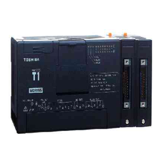
6F3B0253 1. System Configuration 1.5 Components 1.5.1 Basic unit The T1-16S is available in four types as shown in the following table. Type Link/ Calendar Power supply Input Output T1-MDR16SS 100-240 Vac, 8 points - 24 Vdc 6 points - relay, (Enhanced model) 50/60 Hz 2 points - transistor... - Page 24 6F3B0253 1. System Configuration Behind the programmer port cover Programmer port connector Analog setting adjusters (V0 and V1) Mode control switch (HALT / RUN) Battery holder Battery type: CR2032 (Optional) A tab for battery eject Power supply terminals: Connect the power cable and grounding wire. The terminal screw size is M3. See sections 4.4 and 4.5 for wiring.
- Page 25 6F3B0253 1. System Configuration I/O status LEDs: Indicates the ON/OFF status of each I/O signal. (color: red) SW54 setting I/O intending for an indication Note value 0 (default) Basic unit (L: X000-007, H: Y020-027) I/O module slot 0 It indicates these at the time of only RUN I/O module slot 1 mode.
- Page 26 RS-485 port (Enhanced model only): Used to connect a computer (SCADA system), operator interface unit, other T1-16S, or many kinds of serial ASCII devices including Toshiba’s Inverter through RS-485 interface. Refer to section 1.7 for more information about the T1-16S’s RS-485 multi- purpose communication functions.
-
Page 27: I/O Modules
6F3B0253 1. System Configuration 1.5.2 I/O modules The T1-16S can connect up to eight I/O modules. The following 10 types of the I/O modules are available. For specification details of the I/O modules, refer to the separate manual “T1-16S User’s Manual I/O Modules “. -
Page 28: Options
6F3B0253 1. System Configuration 1.5.3 Options The following optional items are available. Item Type Description Cable for CJ105 For T-PDS, 5 m length programming tool Programmer port PT16S For RS-232C computer link, with 2 m cable connector Option card I/O PT15S Cable side connector for Soldering type... -
Page 29: Programmer Port Function
6F3B0253 1. System Configuration 1.6 Programmer port function The interface of the T1-16S’s programmer port is RS-232C. Normally this port is used to connect the programmer. However, this port can also be used for the computer link function. The computer link is a data communication function between computer or operator interface unit and the T1-16S. -
Page 30: Port Communication Function
6F3B0253 1. System Configuration 1.7 RS-485 port communication function The T1-16S enhanced model has an RS-485 multi-purpose communication port. This port can work independent of the programmer port. By using this communication port, one of the following four communication modes is available, computer link mode, data link mode, free ASCII mode, and Inverter connection mode. - Page 31 6F3B0253 1. System Configuration Computer link mode T-series computer link protocol can be used in this mode. A maximum of 32 T1-16Ss can be connected to a master computer. By using this mode, all the T1-16S’s data can be accessed by a master computer. The T-series PLC programming software (T-PDS) can also be used in this configuration.
- Page 32 6F3B0253 1. System Configuration Free ASCII mode The free ASCII mode is used to connect between the T1-16S and various serial ASCII devices, such as a micro computer, bar code reader, printer, display, etc. By using this mode, the T1-16S can work as a communication master. Therefore, the T1-16S can communicate with other PLCs using the computer link protocol.
- Page 33 Free ASCII mode The T1-16S's Inverter connection mode is a special function to monitor/control the Toshiba Inverters (ASDs) VF-A7/G7/S9 through the RS-485 line. Using this mode, the T1-16S can perform the following functions for the Inverters connected on the RS-485 line without any special communication program.
-
Page 34: Real-Time Data Link System
6F3B0253 1. System Configuration 1.8 Real-time data link system TOSLINE-F10 TOSLINE-F10 is a high speed data transmission system suited for small points I/O distribution system. By inserting the TOSLINE-F10 remote module (FR112M), the T1-16S can work as a remote station of the TOSLINE-F10 network. On this network, the T1-16S sends 1 word data to the master station and receives 1 word data from the master station. -
Page 35: Peripheral Tools
T-Series Program Development System (T-PDS) The T-Series Program Development System (T-PDS) is a software which runs on any IBM-PC compatible personal computers such as Toshiba’s Notebook computers. The same T-PDS software supports on-line/off-line programming, debugging and program documentation for all the T-Series programmable controllers T1/T1S, T2/T2E/T2N, T3/T3H and S2T. - Page 36 6F3B0253 1. System Configuration T-Series Handy Programmer (HP911A) The HP911A is a hand-held programmer, that can be used to program the T1-16S using ladder diagram. Its portability makes it ideal for maintenance use at remote locations. The HP911A has the following features. The HP911A supports ladder diagram programming of T-Series programmable controllers T1-16S, T2/T2E/T2N and T3.
- Page 37 6F3B0253 1. System Configuration Program Storage Module (RM102) The program storage module (RM102) is an external memory for storing the T1-16S program. By using the RM102, program saving from the T1-16S to the RM102, and program loading from the RM102 to the T1-16S can be done without need of a programmer.
- Page 38 6F3B0253 T1-16S User’s Manual...
-
Page 39: Specifications
6F3B0253 Section 2 Specifications General specifications, 38 Functional specifications, 40 I/O specifications, 42 External dimensions, 46 Basic Hardware and Function... -
Page 40: General Specifications
6F3B0253 2. Specifications 2.1 General specifications Item T1-16S Power supply voltage 100 to 240Vac (+10/-15%), 50/60 Hz Power consumption 45VA or less Inrush current 50A or less (at 240Vac, cold start) Output 24Vdc 0.2A (for external devices and/or for input signals) rating (24Vdc, ±10%) (Note) - Page 41 6F3B0253 2. Specifications NOTE (3) The 5Vdc current consumption of each I/O modules is described below. Check that the total 5Vdc current consumption is within the limit. Model Specifications 5Vdc consumer current DI116M 16points, 24Vdc-5mA input. 50mA DO116M 16points, 24Vdc-100mA output. 50mA DD116M 8points, 24Vdc-5mA input.
-
Page 42: Functional Specifications
6F3B0253 2. Specifications 2.2 Functional specifications Item T1-16S Control method Stored program, cyclic scan system Scan system Floating scan or constant scan (10 – 200ms, 10ms units) I/O update Batch I/O refresh (direct I/O instruction available at basic unit ’s I/O) Program memory (Note) RAM and EEPROM (no back-up battery required) Program capacity... - Page 43 6F3B0253 2. Specifications Functional specifications (cont’d) Item T1-16S I/O capacity 16 points (basic) +128 points (I/O modules) I/O type Input 24Vdc input (8 points) Output Relay (6 points) + transistor (2 points) I/O terminal block Fixed Real-time clock Yes, 60 s/month at 25°C /calendar (Enhanced model only) Special I/O functions...
-
Page 44: I/O Specifications
6F3B0253 2. Specifications 2.3 I/O specifications Input specifications Item Specifications Input type DC input, current source/sink Number of input points 8 points (8 points/common) Rated input voltage 24Vdc, +10/-15 % Rated input current 7mA (at 24Vdc) Min. ON voltage 15Vdc Max. - Page 45 6F3B0253 2. Specifications Input signal connections T1-16S DC IN Service power 24Vdc 24Vdc 24Vdc input NOTE The 24Vdc service power output is not provided on the DC power supply type. Basic Hardware and Function...
- Page 46 6F3B0253 2. Specifications Output specifications Item Specifications Relay output Transistor output Output type Relay contact, normally open Transistor output, current sink Number of output points 6 points 2 points (6 pts/common) (2 points/common) Rated load voltage 240Vac/24Vdc (max.) 24Vdc Range of load voltage Max.
- Page 47 6F3B0253 2. Specifications Output signal connections T1-16S DC OUT RELAY OUT Service power 24Vdc 240Vac/24Vdc (max.) 24Vdc Transister output Relay output Basic Hardware and Function...
-
Page 48: External Dimensions
6F3B0253 2. Specifications 2.4 External dimensions T1-16S [mm] I/O module [mm] T1-16S User’s Manual... -
Page 49: I/O Application Precautions
6F3B0253 Section 3 I/O Application Precautions Application precautions for input signals, 48 Application precautions for output signals, 50 Basic Hardware and Function... -
Page 50: Application Precautions For Input Signals
6F3B0253 3. I/O Application Precautions 3.1 Application precautions for input signals Configure emergency stop and safety interlocking circuits outside the WARNING T1-16S. Otherwise, malfunction of the T1-16S can cause injury or serious accidents. (1) Minimum ON/OFF time of the input signal The following conditions guarantee correct reading of the ON/OFF state of the input signal: Input ON time: ON delay time + the time for one scan... - Page 51 6F3B0253 3. I/O Application Precautions (4) Countermeasures against leakage current When a switch with an LED or sensor is used, the input sometimes cannot recognize that the switch is off due to the current leakage. In this case, install a bleeder resistor to reduce input impedance.
-
Page 52: Application Precautions For Output Signals
6F3B0253 3. I/O Application Precautions 3.2 Application precautions for output signals Configure emergency stop and safety interlocking circuits outside the WARNING T1-16S. Otherwise, malfunction of the T1-16S can cause injury or serious accidents CAUTION 1. Turn on power to the T1-16S before turning on power to the loads. Failure to do so may cause unexpected behavior of the loads. - Page 53 6F3B0253 3. I/O Application Precautions (3) Over-current protection The output circuit of the T1-16S does not contain protective fuses. Fuses rated for the output should be provided by the user. Load Load output Fuse appropriate to the common current (4) Output surge protection Where an inductive load is connected to the output, a relatively high energy transient voltage will be generated when the relay turns OFF.
- Page 54 6F3B0253 T1-16S User’s Manual...
-
Page 55: Installation And Wiring
6F3B0253 Section 4 Installation and Wiring Environmental conditions, 54 Installing the unit, 55 Wiring terminals, 57 Grounding, 58 Power supply wiring, 59 I/O wiring, 61 Basic Hardware and Function... -
Page 56: Environmental Conditions
6F3B0253 4. Installation and Wiring 4.1 Environmental conditions Excess temperature, humidity, vibration, shocks, or dusty and corrosive CAUTION gas environment can cause electrical shock, fire or malfunction. Install and use the T1-16S and related equipment in the environment described in this section. Do not install the T1-16S in the following locations: Where the ambient temperature drops below 0 C or exceeds 55 C. -
Page 57: Installing The Unit
6F3B0253 4. Installation and Wiring 4.2 Installing the unit 1. Improper installation directions or insufficient installation can cause CAUTION fire or the units to drop. Install the T1-16S and related equipment in accordance with the instructions described in this section. 2. - Page 58 6F3B0253 4. Installation and Wiring Dimensions for screw mounting: T1-16S User’s Manual...
-
Page 59: Wiring Terminals
6F3B0253 4. Installation and Wiring 4.3 Wiring terminals 1. Turn off power before wiring to minimize the risk of electrical shock. CAUTION 2. Exposed conductive parts of wire can cause electrical shock. Use crimp-style terminals with insulating sheath or insulating tape to cover the conductive parts. -
Page 60: Grounding
6F3B0253 4. Installation and Wiring 4.4 Grounding 1. Turn off power before wiring to minimize the risk of electrical shock. CAUTION 2. Operation without grounding may cause electrical shock or malfunction. Connect the ground terminal on the T1-16S to the system ground. The optimum method for grounding electronic equipment is to ground it separately from other high-power systems, and to ground more than one units of electronic equipment with a single-point ground. -
Page 61: Power Supply Wiring
6F3B0253 4. Installation and Wiring 4.5 Power supply wiring 1. Turn off power before wiring to minimize the risk of electrical shock. CAUTION 2. Applying excess power voltage to the T1-16S can cause explosion or fire. Apply power of the specified ratings described below. Wire the power source to the T1-16S power supply terminals. - Page 62 6F3B0253 4. Installation and Wiring Connections of the power supply terminals are shown below. AC power supply type 100-240Vac 100 to 240Vac Grounding DC power supply type 24 Vdc 24Vdc Grounding T1-16S User’s Manual...
-
Page 63: I/O Wiring
6F3B0253 4. Installation and Wiring 4.6 I/O wiring 1. Turn off power before wiring to minimize the risk of electrical shock. CAUTION 2. Exposed conductive parts of wire can cause electrical shock. Use crimp-style terminals with insulating sheath or insulating tape to cover the conductive parts. - Page 64 6F3B0253 T1-16S User’s Manual...
-
Page 65: Operating System Overview
6F3B0253 Section 5 Operating System Overview Operation modes, 64 About the built-in EEPROM, 66 Scanning, 69 Basic Hardware and Function... -
Page 66: Operation Modes
6F3B0253 5. Operating System Overview 5.1 Operation modes The T1-16S has three basic operation modes, the RUN mode, the HALT mode and the ERROR mode. The T1-16S also has the HOLD and RUN-F modes mainly for system checking. RUN: The RUN mode is a normal control-operation mode. In this mode, the T1-16S reads external signals, executes the user program stored in the RAM, and outputs signals to the external devices according to the user program. - Page 67 6F3B0253 5. Operating System Overview The operation modes are switched by the mode control switch provided on the T1-16S and the mode control commands issued from the programming tool. The mode transition conditions are shown below. (Power ON) HALT HOLD RUN-F ERROR Mode control switch is in R (RUN) side.
-
Page 68: About The Built-In Eeprom
6F3B0253 5. Operating System Overview 5.2 About the built-in EEPROM The T1-16S is equipped with a built-in EEPROM and a RAM as standard features. The user program is stored in the EEPROM so that the user program can be maintained without the need of a battery. A part of the Data register can also be stored in the EEPROM. - Page 69 6F3B0253 5. Operating System Overview EEPROM User program User program (8 k steps) (8 k steps) and System info and System info Data register Data register (D0000 to Dnnnn, (0 to 2048 words, user setting) user setting) Other data Other data The rest of Data register and other registers...
- Page 70 6F3B0253 5. Operating System Overview Special register SW55 is used to specify the number of Data registers to be stored in the EEPROM. The allowable setting value is 0 to 2048. The table below shows the correspondence between the SW55 value and Data registers saved in the EEPROM.
-
Page 71: Scanning
6F3B0253 5. Operating System Overview 5.3 Scanning The flowchart below shows the basic internal operations performed by the T1-16S from the time power is turned on through program execution. As the diagram shows, executing a program consists of continuous scanning operations. One scan is a cycle starting with the self-diagnosis and ending with the completion of peripheral support. - Page 72 6F3B0253 5. Operating System Overview Hardware check: Performs checking and initialization of the system ROM, the system RAM and the peripheral LSIs. Initial load: Transfers the user program and user data from the EEPROM to the RAM. (Refer to section 5.2) Register/device initialization: Initializes registers and devices as shown below.
- Page 73 6F3B0253 5. Operating System Overview Self-diagnosis: Checks the proper operation of the T1-16S itself. If an error has detected and cannot be recovered by re-tries, the T1-16S moves into ERROR mode. For the self-diagnosis items, refer to section 10.2. Mode control: Checks the mode control switch status and the mode control request commands from the programming tool.
- Page 74 6F3B0253 5. Operating System Overview User program execution: Executes the programmed instructions from the beginning to the END instruction. This is the essential function of the T1-16S. In this section, only the main program execution is mentioned. For other program types, such as timer interrupt, etc., refer to section 6.5.
-
Page 75: Programming Information
6F3B0253 Section 6 Programming Information Devices and registers, 74 Index modification, 86 Real-time clock/calendar, 88 I/O allocation, 89 T1-16S memory mode setting, 91 User program configuration, 92 Programming language, 98 Program execution sequence, 99 On-line debug support functions, 100 6.10 Password protection, 103 Basic Hardware and Function... -
Page 76: Devices And Registers
6F3B0253 6. Programming Information 6.1 Devices and registers The T1-16S program consists of bit-based instructions that handle ON/OFF information, such as contact and coil instructions, and register-based (16-bit) instructions, such as those for data transfer and arithmetic operations. Devices are used to store the ON/OFF information of contacts and coils, and registers are used to store 16-bit data. - Page 77 6F3B0253 6. Programming Information Addressing devices A device number of X, Y, R and S devices consist of a register number and bit position as follows. X 00 4 Represents bit position 0 to F in the register. Decimal number representing the register containing the corresponding device.
- Page 78 6F3B0253 6. Programming Information Available address range Device/register Symbol T1-16S Number of points Address range External input device Total 512 points X000 - X31F External output device Y020 - Y31F External input register Total 32 words XW00 - XW31 External output register YW02 - YW31 Auxiliary relay device 4096 points...
- Page 79 6F3B0253 6. Programming Information External input devices (X) These devices (X) indicate the ON/OFF states of external input signals through the input circuits. External input devices can be used many times in a program. External output devices (Y) The external output devices (Y) store the ON/OFF signals that drive the external devices through the output circuits.
- Page 80 6F3B0253 6. Programming Information Counter devices and registers (C./C) The counter registers (C) are used for storing the count value of the counter (CNT) and the up-down counter (U/D) instructions. The counter devices (C.) work as the output of the counter instructions. It is possible to specify the C registers as retentive to retain their data in the event of a power failure.
- Page 81 6F3B0253 6. Programming Information Special devices and registers (S/SW) The special devices (S) and special registers (SW) are used for special purposes. See list below. Device/ Name Function register S000 0: Initialization 4: HOLD mode S001 T1/T1S operation mode 1: HALT mode 6: ERROR mode S002 2: RUN mode...
- Page 82 6F3B0253 6. Programming Information Device/ Name Function register S010 System ROM error (down) ON at error state S011 System RAM error (down) ON at error state S012 Program memory error ON at error state (down) S013 EEPROM error (down) ON at error state S014 Reserved S015...
- Page 83 6F3B0253 6. Programming Information Device/ Name Function register S030 Program error ON at error state (related to SW06) S031 Scan time over (down) ON when the scan time exceeds 200 ms S032 Reserved S033 Reserved S034 Reserved S035 Reserved S036 Reserved S037 Reserved...
- Page 84 6F3B0253 6. Programming Information Device/ Name Function register S050 CF (carry flag) Used for instructions which manipulate carry S051 ERF (instruction error flag) ON when instruction execution error is occurred (related to alarm flags of SW06) S052 Reserved S053 Reserved S054 Reserved S055...
- Page 85 6F3B0253 6. Programming Information Device/ Name Function register SW07 Clock/calendar (Year) Lower 2 digits of the calendar year (01, 02, ... ) SW08 Clock/calendar (Month) Month (01, 02, ... 12) They are stored in SW09 Clock/calendar (Day) Day (01, 02, ... 31) the lower 8 bits by SW10 Clock/calendar (Hour)
- Page 86 6F3B0253 6. Programming Information Device/ Name Function register S390 Timer interrupt execution ON during execution status S391 I/O interrupt #1 execution ON during execution status S392 I/O interrupt #2 execution ON during execution status S393 I/O interrupt #3 execution ON during execution status S394 I/O interrupt #4 execution...
- Page 87 6F3B0253 6. Programming Information Device/ Name Function register SW41 Sub-program #1 execution Bit 0 (S410) is ON during the sub-program #1 is status executed SW42 Reserved SW43 Reserved SW44 Reserved SW45 Reserved SW46 Reserved SW47 Reserved SW48 Reserved SW49 Reserved SW50 Reserved SW51...
-
Page 88: Index Modification
6F3B0253 6. Programming Information 6.2 Index modification When registers are used as operands of instructions, the method of directly designating the register address as shown in Example 1) below is called ‘direct addressing’. As opposed to this, the method of indirectly designating the register by combination with the contents of the index register (I, J, or K) as shown in Example 2) below is called ‘indirect addressing’. - Page 89 6F3B0253 6. Programming Information The followings are examples of index modifications. When I = 0, it designates RW10. When I = 1, it designates RW11. RW10 When I = -1, it designates RW09. When I = 10, it designates RW20. When I = -10, it designates RW00.
-
Page 90: Real-Time Clock/Calendar
6F3B0253 6. Programming Information 6.3 Real-time clock/calendar (Enhanced model only) The T1-16S enhanced model is equipped with the real-time clock/calendar for year, month, day, day of the week, hour, minute, and second. These data are stored in the special registers SW07 to SW13 by 2-digit BCD format as follows. -
Page 91: I/O Allocation
6F3B0253 6. Programming Information 6.4 I/O allocation The external input signals are allocated to the external input devices/registers (X/XW). The external output signals are allocated to the external output devices/registers (Y/YW). The register numbers of the external input and output registers are consecutive. Thus one register number can be assigned for either input or output. - Page 92 6F3B0253 6. Programming Information Internally, the T1-16S has information called ‘I/O allocation table’ in its memory. This I/O allocation table shows the correspondence between I/O hardware and software, i.e. register/device. The contents of the I/O allocation table are as follows. Unit Slot I/O type...
-
Page 93: T1-16S Memory Mode Setting
6F3B0253 6. Programming Information 6.5 T1-16S memory mode setting The program capacity of the T1-16S is 8 k steps. However, user can set the T1-16S’s program capacity to 4 k steps. It is called the T1-16S’s memory mode. That is, the T1-16S has two memory modes, 8 k mode and 4 k mode. In the 4 k mode, on-line program changes become available, although the program capacity is limited to 4 k steps. -
Page 94: User Program Configuration
6F3B0253 6. Programming Information 6.6 User program configuration A group of instructions for achieving the PLC-based control system is called ‘user program’. The T1-16S has 8 k steps capacity for storing the user program. A ‘step’ is the minimum unit, which composes an instruction. Number of steps required for one instruction is depending on the type of instruction. - Page 95 6F3B0253 6. Programming Information System information System information is the area which stores execution control parameters. The following contents are included in the system information. (1) Machine parameters (hardware type, memory type) (2) User program information (program ID, system comments, number of steps used) (3) Passwords (4) Retentive register area information (5) T1S program memory mode, 4 k steps or 8 k steps...
-
Page 96: Main Program
6F3B0253 6. Programming Information In the user program, the main program is the core. The scan operation explained in section 5.3 is for the main program. The operation of other program types are explained in the following sections. The following 8 program types are supported by the T1-16S. (1) Main program (2) Sub-program #1 (3) Timer interrupt program... -
Page 97: Sub-Program #1
6F3B0253 6. Programming Information 6.6.2 Sub-program #1 If the sub-program #1 is programmed, it is executed once at the beginning of the first scan (before main program execution). Therefore, the sub-program #1 can be used to set the initial value into the registers. The sub-program #1 is called the initial program. -
Page 98: I/O Interrupt Programs
6F3B0253 6. Programming Information 6.6.4 I/O interrupt programs The I/O interrupt program is also the highest priority task. It is executed immediately when the interrupt factor is generated, with suspending other operation. The following 4 types I/O interrupt programs are supported in the T1/T1S. (1) I/O interrupt #1 The I/O interrupt #1 is used with the high speed counter function. -
Page 99: Subroutines
6F3B0253 6. Programming Information 6.6.5 Subroutines In the program type ‘Subroutine’, The following number of subroutines can be programmed. The T1-16S supports up to 256 subroutines. The subroutine is not a independent program. It is called from other program types (main program, sub-program, interrupt program) and from other subroutines. -
Page 100: Programming Language
6F3B0253 6. Programming Information 6.7 Programming language The programming language of the T1-16S is ‘ladder diagram’. Ladder diagram is a language, which composes program using relay symbols as a base in an image similar to a hard-wired relay sequence. In the T1/T1S, in order to achieve an efficient data-processing program, ladder diagram which are combinations of relay symbols and function blocks are used. -
Page 101: Program Execution Sequence
6F3B0253 6. Programming Information 6.8 Program execution sequence The instructions execution sequence is shown below. (1) They are executed in the sequence from block 1 through the final block, which contains the END instruction (or IRET in an interrupt program). (2) They are executed in the sequence from rung 1 through the final rung in a block (or the END instruction). -
Page 102: On-Line Debug Support Functions
6F3B0253 6. Programming Information 6.9 On-line debug support functions The following on-line (during RUN) functions are supported in the T1-16S for effective program debugging. On-line function 4 k mode 8 k mode Force function Sampling trace function Changing timer /counter preset value Changing constant operand of function instruction... - Page 103 6F3B0253 6. Programming Information Sampling trace function The sampling trace function collects the status of specified devices or register at every specified sampling timing. The collected data can be displayed on the programmer (T-PDS) screen in the format of timing chart (for devices) or trend graph (for register). The minimum sampling timing is the T1-16S’s scan cycle.
- Page 104 6F3B0253 6. Programming Information Timer/counter preset value (constant data) changing The preset value (constant data) of timer or counter instruction can be changed in on- line (during RUN) by using the programming tool. Function instruction constant operand changing The constant operand of function instruction can be changed in on-line (during RUN) by using the programming tool.
-
Page 105: Password Protection
6F3B0253 6. Programming Information 6.10 Password protection The T1-16S has the password function to protect the user program and data from unauthorized operations. There are four levels of protection. Accordingly, three levels of passwords can be registered to control the protection levels. These passwords are stored in the built-in EEPROM. - Page 106 6F3B0253 T1-16S User’s Manual...
-
Page 107: Instructions
6F3B0253 Section 7 Instructions List of instructions, 106 Instruction specifications, 116 Basic Hardware and Function... -
Page 108: List Of Instructions
6F3B0253 7. Instructions 7.1 List of instructions The T1-16S has 21 types of basic ladder instructions and 97 types of function instructions as listed below. The specifications of each instruction will be described in detail later. The tables listing these instructions are provided as a quick reference. (Note: In the following table, italic character means operand, i.e. - Page 109 6F3B0253 7. Instructions Basic ladder instructions (continued) Speed Name Expression Function Steps Page ( s) Counter Counts the number of cycles the count input (C) comes ON while the enable input (E) is ON, and turns ON output (Q) 22.6 when the count reaches to the value specified by A.
- Page 110 6F3B0253 7. Instructions Arithmetic operations Speed Name Expression Function Steps Page ( s) 027 Addition [ A + B Adds data of A and B, and stores the result in C. 028 Subtraction Subtracts data of B from A, [ A - B and stores the result in C.
- Page 111 6F3B0253 7. Instructions Logical operations Speed Name Expression Function Steps Page ( s) 048 AND [ A AND B Finds logical AND of A and B, and stores it in C. 050 OR Finds logical OR of A and B, [ A OR B and stores it in C.
- Page 112 6F3B0253 7. Instructions Rotate operations Speed Name Expression Function Steps Page ( s) 078 1 bit rotate [ RTR1 A ] Rotates data of A 1 bit to the right right (LSB direction). The carry flag changes according to the result. 079 1 bit rotate left [ RTL1 A ] Rotates data of A 1 bit to the...
- Page 113 6F3B0253 7. Instructions Compare instructions (continued) Speed Name Expression Function Steps Page ( s) 108 Unsigned [ A U> B ] Turns ON output if A greater than (Unsigned integer compare) 109 Unsigned [ A U>= B ] Turns ON output if A greater than or (Unsigned integer compare) equal...
- Page 114 6F3B0253 7. Instructions Program control instructions Speed Name Expression Function Steps Page ( s) 128 Subroutine call [ CALL N. n ] Calls the subroutine number n. 21.0 (in a 129 Subroutine [ RET ] Indicates the end of a pair) return subroutine.
- Page 115 6F3B0253 7. Instructions Functions Speed Name Expression Function Steps Page ( s) 056 Moving Calculates the average value [ A MAVE (n) B average of latest n scan values of A, and stores the result in C. 061 Digital filter [ A DFL B Filters the value of A by filter constant specified by B, and...
- Page 116 6F3B0253 7. Instructions Conversion instructions Speed Name Expression Function Steps Page ( s) 062 Hex to ASCII Converts the hexadecimal [ A HTOA (n) B ] conversion data of n words stating with A into ASCII characters, and stores them in nx2 registers starting with B.
- Page 117 6F3B0253 7. Instructions Special I/O instructions Speed Name Expression Function Steps Available Page ( s) 235 Direct I/O Performs the immediate [ I/O (n) A ] 20.7 + block I/O transfer of n 21.3 registers starting with A. 236 Expanded data [ A XFER B Writes data into the built-in 54.0...
-
Page 118: Instruction Specifications
6F3B0253 7. Instructions 7.2 Instruction specifications The following pages in this section describe the detailed specifications of each instruction. On each page, the following items are explained. Expression Shows the operands required for the instruction as italic characters. Function Explains the functions of the instruction with referring the operands shown on the Expression box. -
Page 119: No Contact
6F3B0253 7. Instructions NO contact Expression Input Output Function NO (normally open) contact of device A. When the input is ON and the device A is ON, the output is turned ON. Execution condition Input Operation Output Regardless of the state of device A When device A is OFF When device A is ON Operand... -
Page 120: Nc Contact
6F3B0253 7. Instructions NC contact Expression Input Output Function NC (normally closed) contact of device A. When the input is ON and the device A is OFF, the output is turned ON. Execution condition Input Operation Output Regardless of the state of device A When device A is OFF When device A is ON Operand... - Page 121 6F3B0253 7. Instructions Transitional contact (Rising edge) Expression Input Output Function When the input at last scan is OFF and the input at this scan is ON, the output is turned ON. This instruction is used to detect the input changing from OFF to ON. Execution condition Input Operation...
- Page 122 6F3B0253 7. Instructions Transitional contact (Falling edge) Expression Input Output Function When the input at last scan is ON and the input at this scan is OFF, the output is turned ON. This instruction is used to detect the input changing from ON to OFF. Execution condition Input Operation...
- Page 123 6F3B0253 7. Instructions Coil Expression Input Function Relay coil of device A. When the input is ON, the device A is set to ON. Execution condition Input Operation Output Sets device A to OFF Sets device A to ON Operand Name Device Register...
-
Page 124: Forced Coil
6F3B0253 7. Instructions Forced coil Expression Input Function Regardless of the input sate the state of device A is retained. Execution condition Input Operation Output No operation No operation Operand Name Device Register Constant Index C. XW YW RW SW T A Device Example Device Y025 retains the preceding state regardless of the devices X000 state. - Page 125 6F3B0253 7. Instructions Inverter Expression Input Output Function When the input is OFF, the output is turned ON, and when the input is ON, the output is turned OFF. This instruction inverts the link state. Execution condition Input Operation Output Inverts the input state Inverts the input state Operand...
-
Page 126: Invert Coil
6F3B0253 7. Instructions Invert coil ( I ) Expression Input ( I ) Function When the input is OFF, the device A is set to ON, and when the input is ON, the device A is set to OFF. This instruction inverts the input state and store it in the device A. Execution condition Input Operation... -
Page 127: Positive Pulse Contact
6F3B0253 7. Instructions Positive pulse contact Expression Input Output Function When the input is ON and the device A is changed from OFF to ON (OFF at last scan and ON at this scan), the output is turned ON. This instruction is used to detect the device changing from OFF to ON. Execution condition Input Operation... -
Page 128: Negative Pulse Contact
6F3B0253 7. Instructions Negative pulse contact Expression Input Output Function When the input is ON and the device A is changed from ON to OFF (ON at last scan and OFF at this scan), the output is turned ON. This instruction is used to detect the device changing from ON to OFF. Execution condition Input Operation... -
Page 129: Positive Pulse Coil
6F3B0253 7. Instructions Positive pulse coil ( P ) Expression Input Function When the input is changed form OFF to ON, the device A is set to ON for 1 scan time. This instruction is used to detect the input changing from OFF to ON. Execution condition Input Operation... -
Page 130: Negative Pulse Coil
6F3B0253 7. Instructions Negative pulse coil ( N ) Expression Input Function When the input is changed form ON to OFF, the device A is set to ON for 1 scan time. This instruction is used to detect the input changing from ON to OFF. Execution condition Input Operation... - Page 131 6F3B0253 7. Instructions ON delay timer Expression Input [ A TON B ] Output Function When the input is changed from OFF to ON, timer updating for the timer register B is started. The elapsed time is stored in B. When the specified time by A has elapsed after the input came ON, the output and the timer device corresponding to B is turned ON.
- Page 132 6F3B0253 7. Instructions OFF delay timer Expression Input [ A TOF B ] Output Function When the input is changed from OFF to ON, the output and the timer device corresponding to the timer register B are set to ON. When the input is changed from ON to OFF, timer updating for B is started.
- Page 133 6F3B0253 7. Instructions Single shot timer Expression Input [ A SS B ] Output Function When the input is changed from OFF to ON, the output and the timer device corresponding to the timer register B are set to ON, and timer updating for B is started. The elapsed time is stored in B. When the specified time by A has elapsed after the input came ON, the output and the timer device are turned OFF.
- Page 134 6F3B0253 7. Instructions Counter Expression Count input Output Enable input Function While the enable input is ON, this instruction counts the number of the count input changes from OFF to ON. The count value is stored in the counter register B. When the count value reaches the set value A, the output and the counter device corresponding to B are turned ON.
- Page 135 6F3B0253 7. Instructions Master control set / reset Expression Input [ MCS ] [ MCR ] Function When the MCS input is ON, ordinary operation is performed. When the MCS input is OFF, the state of left power rail between MCS and MCR is turned OFF. Execution condition Operation Output...
- Page 136 6F3B0253 7. Instructions Jump control set / reset Expression Input [ JCS ] [ JCR ] Function When the JCS input is ON, instructions between JCS and JCR are skipped (not executed). When the JCS input is OFF, ordinary operation is performed. Execution condition Operation Output...
- Page 137 6F3B0253 7. Instructions Expression [ END ] Function Indicates the end of main program or sub-program. Instructions after the END instruction are not executed. At least one END instruction is necessary in a program. Execution condition Input Operation Output Operand No operand is required.
- Page 138 6F3B0253 7. Instructions FUN 018 Data transfer Expression Input [ A MOV B ] Output Function When the input is ON, the data of A is stored in B. Execution condition Input Operation Output No execution Execution Operand Name Device Register Constant Index C.
- Page 139 6F3B0253 7. Instructions FUN 019 DMOV Double-word data transfer Expression Input [ A+1 A MOV B+1 B ] Output Function When the input is ON, the double-word (32-bit) data of A+1 A is stored in double-word register B+1 B. The data range is -2147483648 to 2147483647. Execution condition Input Operation...
-
Page 140: Invert Transfer
6F3B0253 7. Instructions FUN 020 Invert transfer Expression Input [ A NOT B ] Output Function When the input is ON, the bit-inverted data of A is stored in B. Execution condition Input Operation Output No execution Execution Operand Name Device Register Constant Index... -
Page 141: Data Exchange
6F3B0253 7. Instructions FUN 022 XCHG Data exchange Expression Input [ A XCHG B ] Output Function When the input is ON, the data of A and the data of B is exchanged. Execution condition Input Operation Output No execution Execution Operand Name... - Page 142 6F3B0253 7. Instructions FUN 024 TINZ Table initialize Expression Input [ A TINZ (n) B ] Output Function When the input is ON, the data of A is stored in n registers starting with B. The allowable range of the table size n is 1 to 1024 words. Execution condition Input Operation...
- Page 143 6F3B0253 7. Instructions FUN 025 TMOV Table transfer Expression Input [ A TMOV (n) B ] Output Function When the input is ON, the data of n registers starting with A are transferred to n registers starting with B in a block. The allowable range of the table size n is 1 to 1024 words. Execution condition Input Operation...
- Page 144 6F3B0253 7. Instructions FUN 026 TNOT Table invert transfer Expression Input [ A TNOT (n) B ] Output Function When the input is ON, the data of n registers starting with A are bit-inverted and transferred to n registers starting with B in a block. The allowable range of the table size n is 1 to 1024 words. Execution condition Input Operation...
- Page 145 6F3B0253 7. Instructions FUN 027 Addition Expression Input [ A + B Output Function When the input is ON, the data of A and the data of B are added, and the result is stored in C. If the result is greater than 32767, the upper limit value 32767 is stored in C, and the output is turned ON.
- Page 146 6F3B0253 7. Instructions FUN 028 Subtraction Expression Input Output Function When the input is ON, the data of B is subtracted from the data of A, and the result is stored in C. If the result is greater than 32767, the upper limit value 32767 is stored in C, and the output is turned ON.
- Page 147 6F3B0253 7. Instructions FUN 029 Multiplication Expression Input C+1 C ] Output Function When the input is ON, the data of A is multiplied by the data of B, and the result is stored in double-length register C+1 C. Execution condition Input Operation Output...
- Page 148 6F3B0253 7. Instructions FUN 030 Division Expression Input [ A / B Output Function When the input is ON, the data of A is divided by the data of B, and the quotient is stored in C and the remainder in C+1. Execution condition Input Operation...
- Page 149 6F3B0253 7. Instructions FUN 031 Double-word addition Expression Input [ A+1 A D+ B+1 B C+1 C ] Output Function When the input is ON, the double-word data of A+1 A and B+1 B are added, and the result is stored in C+1 C.
- Page 150 6F3B0253 7. Instructions FUN 032 Double-word subtraction Expression Input [ A+1 A D B+1 B C+1 C ] Output Function When the input is ON, the double-word data of B+1 B is subtracted from A+1 A, and the result is stored in C+1 C.
- Page 151 6F3B0253 7. Instructions FUN 035 Addition with carry Expression Input [ A +C B Output Function When the input is ON, the data of A, B and the carry flag (CF = S050) are added, and the result is stored in C. If carry is occurred in the operation, the carry flag is set to ON. If the result is greater than 32767 or smaller than -32768, the output is turned ON.
- Page 152 6F3B0253 7. Instructions FUN 036 Subtraction with carry Expression Input [ A -C B Output Function When the input is ON, the data of B and the carry flag (CF = S050) are subtracted from A, and the result is stored in C. If borrow is occurred in the operation, the carry flag is set to ON. If the result is greater than 32767 or smaller than -32768, the output is turned ON.
- Page 153 6F3B0253 7. Instructions FUN 039 Unsigned multiplication Expression Input [ A U C+1 C ] Output Function When the input is ON, the unsigned data of A and B are multiplied, and the result is stored in double-length register C+1 C. The data range of A and B is 0 to 65535 (unsigned 16-bit data) Execution condition Input Operation...
- Page 154 6F3B0253 7. Instructions FUN 040 Unsigned division Expression Input [ A U/ B Output Function When the input is ON, the unsigned data of A is divided by the unsigned data of B, and the quotient is stored in C and the remainder in C+1. The data range of A and B is 0 to 65535 (unsigned 16-bit data) Execution condition Input...
- Page 155 6F3B0253 7. Instructions FUN 041 Unsigned double/single division Expression Input [ A+1 A DIV B Output Function When the input is ON, the double-word data of A+1 A is divided by the data of B, and the quotient is stored in C and the remainder in C+1. The data range of A+1 A is 0 to 4294967295, and the data range of B and C is 0 to 65535.
- Page 156 6F3B0253 7. Instructions FUN 043 Increment Expression Input [ +1 A ] Output Function When the input is ON, the data of A is increased by 1 and stored in A. Execution condition Input Operation Output No execution Execution Operand Name Device Register...
- Page 157 6F3B0253 7. Instructions FUN 045 Decrement Expression Input [ -1 A ] Output Function When the input is ON, the data of A is decreased by 1 and stored in A. Execution condition Input Operation Output No execution Execution Operand Name Device Register...
- Page 158 6F3B0253 7. Instructions FUN 048 Expression Input [ A AND B Output Function When the input is ON, this instruction finds logical AND of A and B, and stores the result in C. Execution condition Input Operation Output No execution Execution Operand Name...
- Page 159 6F3B0253 7. Instructions FUN 050 Expression Input [ A OR B Output Function When the input is ON, this instruction finds logical OR of A and B, and stores the result in C. Execution condition Input Operation Output No execution Execution Operand Name...
-
Page 160: Exclusive Or
6F3B0253 7. Instructions FUN 052 Exclusive OR Expression Input [ A EOR B Output Function When the input is ON, this instruction finds exclusive OR of A and B, and stores the result in C. Execution condition Input Operation Output No execution Execution Operand... - Page 161 6F3B0253 7. Instructions FUN 056 MAVE Moving average Expression Input [ A MAVE (n) B Output Function When the input is ON, this instruction calculates the average value of the latest n scan’s register A data, and stores it in C. The allowable range of n is 1 to 64. This instruction is useful for filtering the analog input signal.
- Page 162 6F3B0253 7. Instructions FUN 061 Digital Filter Expression Input [ A DFL B Output Function When the input is ON, this instruction calculates the following formula to perform digital filtering for input data A by filter constant by B, and stores the result in C. FL y Here;...
- Page 163 6F3B0253 7. Instructions FUN 062 HTOA Hex to ASCII conversion Expression Input [ A HTOA (n) B ] Output Function When the input is ON, the hexadecimal data of n registers starting with A is converted into ASCII characters and stored in B and after. The uppermost digit of source A is stored in lower byte of destination B, and followed in this order.
- Page 164 6F3B0253 7. Instructions FUN 063 ATOH ASCII to Hex conversion Expression Input [ A ATOH (n) B ] Output Function When the input is ON, the ASCII characters stored in n registers starting with A is converted into hexadecimal data and stored in B and after. The lower byte of source A is stored as uppermost digit of destination B, and followed in this order.
- Page 165 6F3B0253 7. Instructions FUN 064 TEST Bit test Expression Input [ A TEST B ] Output Function When the input is ON, this instruction finds logical AND of A and B. Then if the result is not 0, sets the output to ON. Execution condition Input Operation...
- Page 166 6F3B0253 7. Instructions FUN 068 SHR1 1 bit shift right Expression Input [ SHR1 A ] Output Function When the input is ON, the data of register A is shifted 1 bit to the right (LSB direction). 0 is stored in the left most bit (MSB).
-
Page 167: Bit Shift Left
6F3B0253 7. Instructions FUN 069 SHL1 1 bit shift left Expression Input [ SHL1 A ] Output Function When the input is ON, the data of register A is shifted 1 bit to the left (MSB direction). 0 is stored in the right most bit (LSB). - Page 168 6F3B0253 7. Instructions FUN 070 n bit shift right Expression Input [ A SHR n Output Function When the input is ON, the data of register A is shifted n bits to the right (LSB direction) including the carry flag (CF = S050), and stored in B. 0 is stored in upper n bits. After the operation, if the right most bit (LSB) is ON, the output is turned ON.
-
Page 169: N Bit Shift Left
6F3B0253 7. Instructions FUN 071 n bit shift left Expression Input [ A SHL n Output Function When the input is ON, the data of register A is shifted n bits to the left (MSB direction) including the carry flag (CF = S050), and stored in B. 0 is stored in lower n bits. After the operation, if the left most bit (MSB) is ON, the output is turned ON. - Page 170 6F3B0253 7. Instructions FUN 074 Shift register Expression Data input Output Shift input Enable input Function While the enable input is ON, this instruction shifts the data of the bit table, size n starting with A, 1 bit to the left (upper address direction) when the shift input is ON. The state of the data input is stored in A.
- Page 171 6F3B0253 7. Instructions The figure below shows an operation example. (When X009 is changed from OFF to ON) R11F R11E R11D R11C R103 R102 R101 R100 X008 Shift result R011 is turned OFF Note When the shift input is ON, the shift operation is performed every scan. Use a transitional contact for the shift input to detect the state changing.
- Page 172 6F3B0253 7. Instructions FUN 075 Bi-directional shift register Expression Data input Output Shift input Enable input Direction input Function While the enable input (E) is ON, this instruction shifts the data of the bit table, size n starting with A, 1 bit when the shift input (S) is ON. The shift direction is determined by the state of the direction input (L).
- Page 173 6F3B0253 7. Instructions 9 devices starting with R200 (R200 to R208) is specified as a shift register. When R010 is OFF, the data of the shift register is reset to 0. (R200 to R208 are reset to OFF) The carry flag (CF = S050) is also reset to OFF. While R010 is ON the following operation is enabled.
- Page 174 6F3B0253 7. Instructions FUN 078 RTR1 1 bit rotate right Expression Input [ RTR1 A ] Output Function When the input is ON, the data of register A is rotated 1 bit to the right (LSB direction). The pushed out bit state is stored in the left most bit (MSB) and in the carry flag (CF = S050). After the operation, if the right most bit (LSB) is ON, the output is turned ON.
-
Page 175: Bit Rotate Left
6F3B0253 7. Instructions FUN 079 RTL1 1 bit rotate left Expression Input [ RTL1 A ] Output Function When the input is ON, the data of register A is rotated 1 bit to the left (MSB direction). The pushed out bit state is stored in the right most bit (LSB) and in the carry flag (CF = S050). After the operation, if the left most bit (MSB) is ON, the output is turned ON. - Page 176 6F3B0253 7. Instructions FUN 080 n bit rotate right Expression Input [ A RTR n Output Function When the input is ON, the data of register A is rotated n bits to the right (LSB direction), and stored in B. After the operation, if the right most bit (LSB) is ON, the output is turned ON. Execution condition Input Operation...
- Page 177 6F3B0253 7. Instructions FUN 081 n bit rotate left Expression Input [ A RTL n Output Function When the input is ON, the data of register A is rotated n bits to the left (MSB direction), and stored in B. After the operation, if the left most bit (MSB) is ON, the output is turned ON. Execution condition Input Operation...
- Page 178 6F3B0253 7. Instructions FUN 090 Multiplexer Expression Input [ A MPX (n) B Output Function When the input is ON, the data of the register which is designated by B in the table, size n starting with A, is transferred to C. Execution condition Input Operation...
- Page 179 6F3B0253 7. Instructions FUN 091 Demultiplexer Expression Input [ A DPX (n) B Output Function When the input is ON, the data of A is transferred to the register which is designated by B in the table, size n starting with C. Execution condition Input Operation...
- Page 180 6F3B0253 7. Instructions FUN 096 Greater than Expression Input Output Function When the input is ON, the data of A and the data of B are compared, and if A is greater than B, the output is turned ON. Execution condition Input Operation Output...
- Page 181 6F3B0253 7. Instructions FUN 097 Greater than or equal Expression Input Output Function When the input is ON, the data of A and the data of B are compared, and if A is greater than or equal to B, the output is turned ON. Execution condition Input Operation...
- Page 182 6F3B0253 7. Instructions FUN 098 Equal Expression Input Output Function When the input is ON, the data of A and the data of B are compared, and if A is equal to B, the output is turned ON. Execution condition Input Operation Output...
- Page 183 6F3B0253 7. Instructions FUN 099 Not equal Expression Input Output Function When the input is ON, the data of A and the data of B are compared, and if A is not equal to B, the output is turned ON. Execution condition Input Operation...
- Page 184 6F3B0253 7. Instructions FUN 100 Less than Expression Input Output Function When the input is ON, the data of A and the data of B are compared, and if A is less than B, the output is turned ON. Execution condition Input Operation Output...
- Page 185 6F3B0253 7. Instructions FUN 101 Less than or equal Expression Input Output Function When the input is ON, the data of A and the data of B are compared, and if A is less than or equal to B, the output is turned ON. Execution condition Input Operation...
- Page 186 6F3B0253 7. Instructions FUN 102 Double-word greater than Expression Input [ A+1 A D B+1 B ] Output Function When the input is ON, the double-word data of A+1 A and B+1 B are compared, and if A+1 A is greater than B+1 B, the output is turned ON.
- Page 187 6F3B0253 7. Instructions FUN 103 Double-word greater than or equal Expression Input [ A+1 A D B+1 B ] Output Function When the input is ON, the double-word data of A+1 A and B+1 B are compared, and if A+1 A is greater than or equal to B+1 B, the output is turned ON.
- Page 188 6F3B0253 7. Instructions FUN 104 Double-word equal Expression Input [ A+1 A D B+1 B ] Output Function When the input is ON, the double-word data of A+1 A and B+1 B are compared, and if A+1 A is equal to B+1 B, the output is turned ON. Execution condition Input Operation...
- Page 189 6F3B0253 7. Instructions FUN 105 Double-word not equal Expression Input [ A+1 A D B+1 B ] Output Function When the input is ON, the double-word data of A+1 A and B+1 B are compared, and if A+1 A is not equal to B+1 B, the output is turned ON.
-
Page 190: Double-Word Less Than
6F3B0253 7. Instructions FUN 106 Double-word less than Expression Input [ A+1 A D B+1 B ] Output Function When the input is ON, the double-word data of A+1 A and B+1 B are compared, and if A+1 A is less than B+1 B, the output is turned ON. - Page 191 6F3B0253 7. Instructions FUN 107 Double-word less than or equal Expression Input [ A+1 A D B+1 B ] Output Function When the input is ON, the double-word data of A+1 A and B+1 B are compared, and if A+1 A is less than or equal to B+1 B, the output is turned ON.
- Page 192 6F3B0253 7. Instructions FUN 108 Unsigned greater than Expression Input [ A U Output Function When the input is ON, the data of A and the data of B are compared, and if A is greater than B, the output is turned ON. Execution condition Input Operation...
- Page 193 6F3B0253 7. Instructions FUN 109 Unsigned greater than or equal Expression Input Output Function When the input is ON, the data of A and the data of B are compared, and if A is greater than or equal to B, the output is turned ON. Execution condition Input Operation...
- Page 194 6F3B0253 7. Instructions FUN 110 Unsigned equal Expression Input [ A U Output Function When the input is ON, the data of A and the data of B are compared, and if A is equal to B, the output is turned ON. Execution condition Input Operation...
- Page 195 6F3B0253 7. Instructions FUN 111 Unsigned not equal Expression Input [ A U Output Function When the input is ON, the data of A and the data of B are compared, and if A is not equal to B, the output is turned ON.
- Page 196 6F3B0253 7. Instructions FUN 112 Unsigned less than Expression Input [ A U Output Function When the input is ON, the data of A and the data of B are compared, and if A is less than B, the output is turned ON. Execution condition Input Operation...
- Page 197 6F3B0253 7. Instructions FUN 113 Unsigned less than or equal Expression Input [ A U Output Function When the input is ON, the data of A and the data of B are compared, and if A is less than or equal to B, the output is turned ON.
- Page 198 6F3B0253 7. Instructions FUN 114 Device/register set Expression Input [ SET A ] Output Function When the input is ON, the device A is set to ON if A is a device, or the data HFFFF is stored in the register A if A is a register.
- Page 199 6F3B0253 7. Instructions FUN 115 Device/register reset Expression Input [ RST A ] Output Function When the input is ON, the device A is reset to OFF if A is a device, or the data 0 is stored in the register A if A is a register.
-
Page 200: Set Carry
6F3B0253 7. Instructions FUN 118 SETC Set carry Expression Input [ SETC ] Output Function When the input is ON, the carry flag (CF = S050) is set to ON. Execution condition Input Operation Output No execution Execution Operand No operand is required. Example When R011 is changed from OFF to ON, the carry flag S050 is set to ON. -
Page 201: Reset Carry
6F3B0253 7. Instructions FUN 119 RSTC Reset carry Expression Input [ RSTC ] Output Function When the input is ON, the carry flag (CF = S050) is reset to OFF. Execution condition Input Operation Output No execution Execution Reset Operand No operand is required. - Page 202 6F3B0253 7. Instructions FUN 120 Encode Expression Input [ A ENC (n) B ] Output Function When the input is ON, this instruction finds the bit position of the most significant ON bit in the bit table, size 2 bits starting with 0 bit (LSB) of A, and stores it in B. Execution condition Input Operation...
- Page 203 6F3B0253 7. Instructions FUN 121 Decode Expression Input [ A DEC (n) B ] Output Function When the input is ON, this instruction sets the bit position which is designated by lower n bits of A to ON in the bit table, size 2 bits starting with 0 bit (LSB) of B, and resets all other bits to OFF.
- Page 204 6F3B0253 7. Instructions FUN 122 Bit count Expression Input [ A BC B ] Output Function When the input is ON, this instruction counts the number of ON (1) bits of A, and stores the result in B. Execution condition Input Operation Output...
- Page 205 6F3B0253 7. Instructions FUN 128 CALL Subroutine call Expression Input [ CALL N. n ] Output Function When the input is ON, this instruction calls the subroutine number n. Execution condition Input Operation Output No execution Execution Operand Name Device Register Constant Index C.
- Page 206 6F3B0253 7. Instructions FUN 129 Subroutine return Expression [ RET ] Function This instruction indicates the end of a subroutine. When program execution is reached this instruction, it is returned to the original CALL instruction. Execution condition Input Operation Output Execution Operand No operand is required.
- Page 207 6F3B0253 7. Instructions FUN 132 FOR (FOR-NEXT loop) Expression Input [ FOR n ] Output Function When the input is ON, the program segment between FOR and NEXT is executed n times repeatedly in a scan. When the input is OFF, the repetition is not performed. (the segment is executed once) Execution condition Input Operation...
- Page 208 6F3B0253 7. Instructions FUN 133 NEXT NEXT (FOR-NEXT loop) Expression Input [ NEXT ] Output Function This instruction configures a FOR-NEXT loop. If the input is OFF, The repetition is forcibly broken. and the program execution is moved to the next instruction.
- Page 209 6F3B0253 7. Instructions FUN 137 SUBR Subroutine entry Expression [ SUBR (n) ] Function This instruction indicates the begging of a subroutine. Execution condition Input Operation Output Execution Operand Name Device Register Constant Index C. XW YW RW SW T n Subroutine (Note) number...
- Page 210 6F3B0253 7. Instructions FUN 140 Enable interrupt Expression Input [ EI ] Output Function When the input is ON, this instruction enables the execution of user designated interrupt operation, i.e. timer interrupt program and I/O interrupt programs. Execution condition Input Operation Output No execution...
- Page 211 6F3B0253 7. Instructions FUN 141 Disable interrupt Expression Input [ DI ] Output Function When the input is ON, this instruction disables the execution of user designated interrupt operation, i.e. timer interrupt program and I/O interrupt programs. Execution condition Input Operation Output No execution...
- Page 212 6F3B0253 7. Instructions FUN 142 IRET Interrupt return Expression [ IRET ] Function This instruction indicates the end of an interrupt program. When program execution reaches this instruction, it returns to the original location of the main program (or subroutine). Execution condition Input Operation...
-
Page 213: Watchdog Timer Reset
6F3B0253 7. Instructions FUN 143 Watchdog timer reset Expression Input [ WDT n ] Output Function When the input is ON, this instruction extend the scan time over detection time by 200 ms. Normally, T1/T1S detects the scan time-over if a scan is not finished within 200 ms. This instruction can be used to extend the detection time. - Page 214 6F3B0253 7. Instructions FUN 144 STIZ Step sequence initialize Expression Input [ STIZ (n) A ] Output Function When the input is ON, n devices starting with A are reset to OFF, and A is set to ON. This instruction is used to initialize a series of step sequence. The step sequence is useful to describe a sequential operation.
- Page 215 6F3B0253 7. Instructions FUN 145 STIN Step sequence input Expression Input [ STIN A ] Output Function When the input is ON and the device A is ON, the output is set to ON. Execution condition Input Operation Output No execution When A is ON When A is OFF Operand...
- Page 216 6F3B0253 7. Instructions FUN 146 STOT Step sequence output Expression Input [ STOT A ] Function When the input is ON, the device A is set to ON and the devices of STIN instructions on the same rung are reset to OFF. Execution condition Input Operation...
- Page 217 6F3B0253 7. Instructions FUN 147 Flip-flop Expression Set input Output Reset input Function When the set input is ON, the device A is set to ON. When the reset input is ON, the device A is reset to OFF. When both the set and reset inputs are OFF, the device A remains the state. If both the set and reset inputs are ON, the device A is reset to OFF.
- Page 218 6F3B0253 7. Instructions FUN 149 Up-down counter Expression Direction input Output Count input Enable input Function While the enable input is ON, this instruction counts the number of the count input changes from OFF to ON. The count direction (up count or down count) is selected by the state of the direction input.
- Page 219 6F3B0253 7. Instructions FUN 154 CLND Set calendar Expression Input [ A CLND ] Output Function When the input is ON, the built-in clock/calendar is set to the date and time specified by 6 registers starting with A. If an invalid data is contained in the registers, the operation is not executed and the output is turned ON.
- Page 220 6F3B0253 7. Instructions FUN 155 CLDS Calendar operation Expression Input [ A CLDS B ] Output Function When the input is ON, this instruction subtracts the date and time stored in 6 registers starting with A from the current date and time, and stores the result in 6 registers starting with B. If an invalid data is contained in the registers, the operation is not executed and the output is turned ON.
-
Page 221: Pre-Derivative Real Pid
6F3B0253 7. Instructions FUN 156 PID3 Pre-derivative real PID Expression Input [ A PID3 B Output Function Performs PID (Proportional, Integral, Derivative) control which is a fundamental method of feed- back control. (Pre-derivative real PID algorithm) This PID3 instruction has the following features. For derivative action, incomplete derivative is used to suppress interference of high-frequency noise and to expand the stable application range, Controllability and stability are enhanced in case of limit operation for MV, by using digital PID... - Page 222 6F3B0253 7. Instructions Control block diagram Integral control Integral Auto mode Proportional Differential Derivative Cascade mode DMMV Manual 1+ T Differential limit mode ( = 0.1) MVS: Velocity Position = MV 1+T s H/L: Upper / lower limit DMV: Differential limit Digtal filter Integral action control: When MV is limited (H/L, DMV) and the integral value has same sign as limit over, integral action...
- Page 223 6F3B0253 7. Instructions PID algorithm: Here, (If GP 0, Gap is applied) t Ir (If T = 0, then I = 0) (Fixed) Parameter details Process input value PVC (0.00 to 100.00 %) Data range: 0 to 10000 Auto mode set value ASV (0.00 to 100.00 %) Data range: 0 to 10000 Cascade mode set value CSV (0.00 to 100.00 %) Data range: 0 to 10000...
- Page 224 6F3B0253 7. Instructions Initial status STS Initial operation mode 00 : Manual mode 01 : Auto mode 10 : Cascade mode 11 : (Reserve) Direct / reverse selection 0 : Direct 1 : Reverse MV upper limit MH (-25.00 to 125.00 %) Data range: -2500 to 12500 B+10 MV lower limit ML (-25.00 to 125.00 %)
- Page 225 6F3B0253 7. Instructions Manual mode In this mode, the manipulation value MV can be directly controlled by the input value of MMV. MV differential limit for manual mode DMMV is effective. MH/ML and DMV are not effective. When mode is changed from manual to auto or cascade, the operation is started from the current MV. Cascade mode This is a mode for PID cascade connection.
- Page 226 6F3B0253 7. Instructions FUN 160 Upper limit Expression Input [ A UL B Output Function When the input is ON, the following operation is executed. (Upper limit for A by B) If A B, then C = A. If A B, then C = B.
- Page 227 6F3B0253 7. Instructions FUN 161 Lower limit Expression Input [ A LL B Output Function When the input is ON, the following operation is executed. (Lower limit for A by B) If A B, then C = A. If A B, then C = B.
- Page 228 6F3B0253 7. Instructions FUN 162 Maximum value Expression Input [ A MAX (n) B ] Output Function When the input is ON, this instruction searches for the maximum value from the table of size n words starting with A, and stores the maximum value in B and the pointer indicating the position of the maximum value in B+1.
- Page 229 6F3B0253 7. Instructions FUN 163 Minimum value Expression Input [ A MIN (n) B ] Output Function When the input is ON, this instruction searches for the minimum value from the table of size n words starting with A, and stores the minimum value in B and the pointer indicating the position of the minimum value in B+1.
- Page 230 6F3B0253 7. Instructions FUN 164 Average value Expression Input [ A AVE (n) B ] Output Function When the input is ON, this instruction calculates the average value of the data stored in the n registers starting with A, and stores the average value in B. The allowable range of the table size n is 1 to 64.
- Page 231 6F3B0253 7. Instructions FUN 165 Function generator Expression Input [ A FG (n) B Output Function When the input is ON, this instruction finds the function value f(x) for A as x, and stores it in C. The function f(x) is defined by the parameters stored in 2 n registers starting with B.
- Page 232 6F3B0253 7. Instructions Parameter table 4 registers for x parameters and subsequent 4 registers for corresponding f(x) parameters y = f(x) 1800 D0600 -2000 D0601 -100 D0602 D0603 2000 -2000 -100 2000 D0604 -1800 -300 D0605 -300 D0606 D0607 1800 -1800 The FG instruction interpolators f(x) value for x based on the n parameters of (x For example, if XW04 is 1500 (x = 1500), the result 1405 (f(x) = 1405) is stored in D0100.
- Page 233 6F3B0253 7. Instructions FUN 180 Absolute value Expression Input [ A ABS B ] Output Function When the input is ON, this instruction finds the absolute value of operand A, and stores it in B. Execution condition Input Operation Output No execution Execution Operand...
- Page 234 6F3B0253 7. Instructions FUN 182 2’s complement Expression Input [ A NEG B ] Output Function When the input is ON, this instruction finds the 2’s complement value of A, and stores it in B. Execution condition Input Operation Output No execution Execution Operand...
- Page 235 6F3B0253 7. Instructions FUN 183 DNEG Double-word 2’s complement Expression Input [ A+1 A DNEG B+1 B ] Output Function When the input is ON, this instruction finds the 2’s complement value of double-word data A+1 A, and stores it in B+1 B. Execution condition Input Operation...
- Page 236 6F3B0253 7. Instructions FUN 185 7SEG 7 segment decode Expression Input [ A 7SEG B ] Output Function When the input is ON, this instruction converts the lower 4 bits data of A into the 7 segment code, and stores it in B. The 7 segment code is normally used for a numeric display LED. Execution condition Input Operation...
- Page 237 6F3B0253 7. Instructions Operand A (lower 4 bits) 7 segment LED Operand B (lower 8 bits) Display Binary composition B7 B6 B5 B4 B3 B2 B1 B0 0000 0001 0010 0011 0100 0101 0110 0111 1000 1001 1010 1011 1100 1101 1110 1111...
- Page 238 6F3B0253 7. Instructions FUN 186 ASCII conversion Expression Input [ A ASC B ] Output Function When the input is ON, this instruction converts the alphanumeric characters into the ASCII codes, and stores them in the register table starting with B. (16 characters maximum) Execution condition Input Operation...
- Page 239 6F3B0253 7. Instructions FUN 188 Binary conversion Expression Input [ A BIN B ] Output Function When the input is ON, this instruction converts the 4 digits of BCD data of A into binary, and stores in B. If any digit of A contains non-BCD code (other than H0 through H9), the conversion is not executed and the instruction error flag (ERF = S051) is set to ON.
- Page 240 6F3B0253 7. Instructions FUN 190 BCD conversion Expression Input [ A BCD B ] Output Function When the input is ON, this instruction converts the binary data of A into BCD, and stores in B. If the data of A is not in the range of 0 to 9999, the conversion is not executed and the instruction error flag (ERF = S051) is set to ON.
- Page 241 6F3B0253 7. Instructions FUN 235 Direct I/O Expression Input [ I/O (n) A ] Output Function When the input is ON, this instruction immediately updates the external input (XW) and output (YW) registers which are in the range of n registers starting with A. For XW register ...
- Page 242 6F3B0253 7. Instructions Note In the T1-16S, the following register/device range is only effective for this Direct I/O instruction. Input on basic unit Output on basic unit I/O module X000 - X007 Y020 - Y027 Not effective The Direct I/O instruction can be programmed in the main program and in the interrupt program. If this instruction is programmed in both, the instruction in the main program should be executed in interrupt disable state.
-
Page 243: Expanded Data Transfer
6F3B0253 7. Instructions FUN 236 XFER Expanded data transfer Expression Input [ A XFER B Output Function When the input is ON, data block transfer is performed between the source which is indirectly designated by A and A+1 and the destination which is indirectly designated by C and C+1. The transfer size (number of words) is designated by B. - Page 244 6F3B0253 7. Instructions CPU register built-in EEPROM In the EEPROM, the D registers are divided into pages as follows. T1-16S D0000 Page 1 Writing data into the EEPROM is (32 words) available within one page at a D0031 time. (max. 32 words) D0032 Page 2 (32 words)
- Page 245 6F3B0253 7. Instructions CPU register T1S RS-485 port <Receiving> When the instruction input is ON, one set of message (from start character to the trailing code) which is received by the RS-485 port is read from the receive buffer, and stored in the CPU registers.
- Page 246 6F3B0253 7. Instructions <Transmitting> When the instruction input is ON, one set of message which is stored in the source table (from start character to the trailing code) is transmitted through the RS-485 port. The execution status is stored in the status flag. The instruction input must be kept ON until the transmitting operation is complete.
- Page 247 Output Function This function is provided to control Toshiba Inverters VF-A7/G7/S9 connected on the RS-485 line. When the RS-485 port operation mode is set to the Inverter mode (SW56 = 3), the T1-16S can perform the following functions for up to 63 Inverters.
- Page 248 6F3B0253 7. Instructions Operation mode designation (B+1): Operation mode Description Data exchange mode Cyclically scans the connected Inverters (Control & Monitor) (Mode 0) (Inverter command: P+FA01&FA00 and R+FD00&FE07) Monitor mode Cyclically scans the connected Inverters (Monitor only) (Mode 1) (Inverter command: R+FD00&FE07) Read command mode Sends a read command to a specified Inverter (Mode 2)
- Page 249 6F3B0253 7. Instructions < Data exchange mode (Mode 0) > When the instruction input comes ON with the operand B+1 is 0, the Data exchange mode (mode 0) is selected. In this mode, the T1-16S sends the following commands to the Inverters starting from #0 through the Inverter number specified by the operand B, and repeats.
- Page 250 6F3B0253 7. Instructions Data table: Register Data contents Signal direction D2000 #0 Operating frequency Read D2001 #0 Output terminal status Read D2002 #0 Frequency reference Write D2003 #0 Operation command Write D2004 #1 Operating frequency Read D2005 #1 Output terminal status Read D2006 #1 Frequency reference Write...
- Page 251 6F3B0253 7. Instructions < Monitor mode (Mode 1) > When the instruction input comes ON with the operand B+1 is 1, the Monitor mode (mode 1) is selected. In this mode, the T1-16S sends the following Read commands to the Inverters starting from #0 through the Inverter number specified by the operand B, and repeats.
- Page 252 6F3B0253 7. Instructions Data table: Register Data contents Signal direction RW100 #0 Operating frequency Read RW101 #0 Output terminal status Read RW102 No use RW103 No use RW104 #1 Operating frequency Read RW105 #1 Output terminal status Read RW106 No use RW107 No use RW176 #19 Operating frequency...
- Page 253 6F3B0253 7. Instructions < Read command mode (Mode 2) > When the instruction input comes ON with the operand B+1 is 2, the Read command mode (mode 2) is selected. In this mode, the T1-16S sends the user specified Read command to the Inverter specified by the operand B, and repeats.
- Page 254 6F3B0253 7. Instructions < Write command mode (Mode 3) > When the instruction input comes ON with the operand B+1 is 3, the Write command mode (mode 3) is selected. In this mode, the T1-16S sends the user specified Write command to the Inverter specified by the operand B, and repeats.
- Page 255 6F3B0253 7. Instructions < Broadcast mode (Mode 4) > When the instruction input comes ON with the operand B+1 is 4, the Broadcast mode (mode 4) is selected. In this mode, the T1-16S sends the user specified Write command to all the Inverters as broadcast.
- Page 256 6F3B0253 7. Instructions < Note > (1) The XFER instruction is not executed as error in the following cases. In these cases, the instruction error flag (ERF = S051) is set to ON. If the ERF is set to ON once, it remains ON until resetting to OFF by user program.
-
Page 257: Special I/O Functions
6F3B0253 Section 8 Special I/O Functions Special I/O function overview, 256 Variable input filter constant, 260 High speed counter, 261 Interrupt input function, 268 Analog setting function, 270 Pulse output function, 271 PWM output function, 273 Basic Hardware and Function... -
Page 258: Special I/O Function Overview
6F3B0253 8. Special I/O Functions 8.1 Special I/O function overview The T1-16S supports the special I/O functions as listed below. Function name Function summary Remarks Variable input filter Input filter constant (ON/OFF delay time) can be set SW16 setting constant by user program. - Page 259 6F3B0253 8. Special I/O Functions Mode setting for the special I/O functions These functions, except the analog setting function, are selected by setting data into SW16 and SW26 by user program. These registers work as mode setting registers for the special I/O functions. The data setting for these registers, i.e. mode setting for the special I/O functions, is effective only at the first scan.
- Page 260 6F3B0253 8. Special I/O Functions Note) In the explanation below, P-OUT means the pulse output function. F E D C B A 9 8 7 6 5 4 3 2 1 0 SW26 0 0 0 0 0 0 0 0 0 0 Bit 0 <...
- Page 261 6F3B0253 8. Special I/O Functions The table below summarizes the mode setting data of each function. In the table, ‘ ’ means do not care. SW16 Variable input filter constant F E D C B A 9 8 7 6 5 4 3 2 1 0 SW16 High speed counter F E D C B A 9 8 7 6 5 4 3 2 1 0...
-
Page 262: Variable Input Filter Constant
6F3B0253 8. Special I/O Functions 8.2 Variable input filter constant Function The input filter constant (ON/OFF delay time) of the leading 8 points X000 to X007 can be specified by user program within the range of 0 to 15ms. The default is 10ms. The setting value is recognized at the first scan. -
Page 263: High Speed Counter
6F3B0253 8. Special I/O Functions 8.3 High speed counter 8.3.1 Single phase up-counter Function When the count input is changed from OFF to ON, the count value is increased by 1. When the count value reaches the set value, the count value is reset to 0, and I/O interrupt program is activated (if the interrupt enable flag is ON). -
Page 264: Single Phase Up-Counter
6F3B0253 8. Special I/O Functions Operation Count input Reset input Soft-gate Set value Count value Interrupt Sample program (H1003) In this example, 4099 (H1003) is set in SW16. As a result, the single phase up- counter (channel 1 only) is selected. When R010 comes ON, the data 2000 is written into the set value register (SW18). -
Page 265: Single Phase Speed-Counter
6F3B0253 8. Special I/O Functions 8.3.2 Single phase speed-counter Function This function counts the number of changes of the count input from OFF to ON during the every specified sampling time. The count value in a sampling time is stored in the hold value register. - Page 266 6F3B0253 8. Special I/O Functions Operation Count input Sampling time Soft-gate Internal count value Hold value Sample program (H1403) In this example, 5123 (H1403) is set in SW16. As a result, the single phase speed- counter (channel 1 only) is selected. The sampling time is set as 100ms, because 10 is written in SW18.
-
Page 267: Quadrature Bi-Pulse Counter
6F3B0253 8. Special I/O Functions 8.3.3 Quadrature bi-pulse counter Function This function counts up or down the quadrature bi-pulse (2-phase pulses whose phases are shifted 90 each other). Counts up when phase A precedes, and counts down when phase B precedes. Both rising and falling edges of each phase are counted. - Page 268 6F3B0253 8. Special I/O Functions Interrupt assignment Comparison value 1 I/O interrupt program #1 Comparison value 2 I/O interrupt program #2 Operation Up count Down count Reset input Soft-gate 2147483647 Comparison value 1 Count value Comparison value 2 -2147483648 Interrupt T1-16S User’s Manual...
- Page 269 6F3B0253 8. Special I/O Functions Sample program (H0803) In this example, 2051 (H0803) is set in SW16. As a result, the quadrature bi-pulse counter is selected. When R010 comes ON, the data 150000 is set into the comparison value 1 register (SW19 SW18), and 200000 is set into the comparison value 2 register (SW21 SW20).
-
Page 270: Interrupt Input Function
6F3B0253 8. Special I/O Functions 8.4 Interrupt input function Function When the signal state of the interrupt input is changed from OFF to ON (or ON to OFF), the corresponding I/O interrupt program is activated immediately. Up to 2 interrupt inputs can be used. The interrupt generation condition can be selected either rising edge (OFF to ON) or falling edge (ON to OFF) for each input. - Page 271 6F3B0253 8. Special I/O Functions Sample program Main program (H3045) I/O interrupt program #3 Interrupt program A I/O interrupt program #4 Interrupt program B In this example, 12357 (H3045) is set in SW16. As a result, the interrupt input function (2 points, rising for both) is selected.
-
Page 272: Analog Setting Function
6F3B0253 8. Special I/O Functions 8.5 Analog setting function Function The value of the analog setting adjuster is converted into a digital value (0 to 1000) and stored in the SW register. 2 adjusters are provided. (V0 and V1) The SW register data can be used as timer presets or any parameters for function instructions. -
Page 273: Pulse Output Function
6F3B0253 8. Special I/O Functions 8.6 Pulse output function Function This function is used to output a variable frequency pulse train. The controllable pulse frequency is 50 to 5000 Hz (1 Hz units). The output mode can be selected either CW/CCW or Pulse/Direction (PLS/DIR). In the CW/CCW mode, CW pulse is output when the frequency setting is positive (50 to 5000), and CCW pulse is output when it is negative (-50 to -5000). - Page 274 6F3B0253 8. Special I/O Functions Operation Pulse enable Frequency setting -1000 -300 1000 -100 1KHz Frequency 300Hz 100Hz Pulse output 100Hz 300Hz 1KHz Sample program In this example, 3 (H0003) is set in SW26. As a result, the CW/CCW mode pulse output function is selected.
-
Page 275: Pwm Output Function
6F3B0253 8. Special I/O Functions 8.7 PWM output function Function This function is used to output a variable duty cycle pulse train. The controllable duty cycle is 0 to 100 % (1 % units). ON duty T = Pulse cycle The PWM output is enabled when the pulse enable flag is ON. - Page 276 6F3B0253 8. Special I/O Functions Operation Pulse enable ON duty setting ON duty PWM output Sample program In this example, 1 (H0001) is set in SW26 and 100 is set in SW28. As a result, 100 Hz PWM output function is selected. When R005 is ON, the PWM output is started with the duty cycle designated by D0200.
-
Page 277: Maintenance And Checks
6F3B0253 Section 9 Maintenance and Checks Precautions during operation, 276 Daily checks, 277 Periodic checks, 278 Maintenance parts, 279 Battery, 280 Basic Hardware and Function... -
Page 278: Precautions During Operation
6F3B0253 9. Maintenance and Checks 9.1 Precautions during operation When the T1-16S is in operation, you should pay attention to the following items. (1) The programmer cable can be plugged or unplugged while the T1-16S is in operation. When you try to do it, do not touch the connector pins. This may cause malfunction of the T1-16S owing to static electricity. -
Page 279: Daily Checks
6F3B0253 9. Maintenance and Checks 9.2 Daily checks 1. Pay special attention during the maintenance work to minimize the risk CAUTION of electrical shock. 2. Turn off power immediately if the T1-16S or related equipment is emitting smoke or odor. Operation under such situation can cause fire or electrical shock. -
Page 280: Periodic Checks
6F3B0253 9. Maintenance and Checks 9.3 Periodic checks 1. Pay special attention during the maintenance work to minimize the risk CAUTION of electrical shock. 2. Turn off power immediately if the T1-16S or related equipment is emitting smoke or odor. Operation under such situation can cause fire or electrical shock. -
Page 281: Maintenance Parts
6F3B0253 9. Maintenance and Checks (Periodic checks - continued) Item Check Criteria Environment Check that the temperature, humidity, Must be within the range of vibration, dust, etc. are within the general specification. specified range. Programming tool Check that the functions of the Monitoring and other operations programming tool are normal. -
Page 282: Battery
6F3B0253 9. Maintenance and Checks 9.5 Battery (1) Install Insert the battery by an angle of 45°. + side (Turn + side into an upside.) (1) Push the battery horizontal direction. (2) Push from upside and lock. (2) Eject Push the center of the tab by a finger or a pen. Then the battery will be unlocked. -
Page 283: Troubleshooting Procedure
6F3B0253 Section 10 Troubleshooting 10.1 Troubleshooting procedure, 282 10.2 Self-diagnostic items, 288 Basic Hardware and Function... - Page 284 Failure to do so can cause electrical shock or damage to the T1 and related equipment. 4. Contact Toshiba for repairing if the T1-16S or related equipment is failed. Toshiba will not guarantee proper operation nor safety for unauthorized repairing.
-
Page 285: Power Supply Check
6F3B0253 10. Troubleshooting 10.1.1 Power supply check If the PWR (power) LED is not lit after power on, check the following points. Check the power connection Connection terminals are correct. The terminal screws are not loose. The terminal block is installed securely. Correct Check the power voltage 85 to 132/170 to 264Vac (50/60 Hz) -
Page 286: Cpu Check
6F3B0253 10. Troubleshooting 10.1.2 CPU check If the PWR (power) LED is lit but the RUN LED is not lit, check the following points. Check the position of the If it is not in R (RUN) position, turn the mode control switch switch to R (RUN) position. -
Page 287: Input Check
6F3B0253 10. Troubleshooting 10.1.4 Input check If the program is running but the external input signal is not read normally, check the following points: Is the input status LED If not, check the input voltage at the changed ON/OFF according T1-16S’s input terminals. -
Page 288: Output Check
6F3B0253 10. Troubleshooting 10.1.5 Output check If the output status monitored on the programming tool is normal but the external output device (load) is not operated normally, check the following points: Is the output status LED changed ON/OFF according to the program execution ? Check the voltage between If it is the circuit voltage at the output is the output terminal and its... -
Page 289: Environmental Problem
6F3B0253 10. Troubleshooting 10.1.6 Environmental problem If the following improper operations occur in the controlled system, check possible environmental factors. (1) If an improper operation occurs synchronously with the operation of I/O devices: The noise generated at ON/OFF of the output device (load) may be the cause of the problem. -
Page 290: Self-Diagnostic Items
6F3B0253 10. Troubleshooting 10.2 Self-diagnostic items If an error is detected by the self-diagnostic check of the T1-16S CPU, the error messages and the related information shown on the following pages will be recorded in the T1-16S’s event history table. If the error is severe and continuation of operation is not possible, the T1-16S turns OFF all outputs and stops the operation (ERROR mode). - Page 291 6F3B0253 10. Troubleshooting Error message and related information Special Meaning and countermeasures Event Info 1 Info 2 Info 3 device Batt voltage drop S00F In the power-up initialization, data invalidity of RAM (back-up area) has been detected. If retentive registers are used, these validity are not guaranteed.
- Page 292 6F3B0253 10. Troubleshooting Error message and related information Special Meaning and countermeasures Event Info 1 Info 2 Info 3 device Illegal inst Program Address S006 An illegal instruction has been detected in type - in the S030 the program. (Error down) block No.
- Page 293 6F3B0253 10. Troubleshooting Error message and related information Special Meaning and countermeasures Event Info 1 Info 2 Info 3 device Operand error Program Address A register/device which is not supported by type - in the the T1-16S is programmed. (Error down) block No.
- Page 294 6F3B0253 10. Troubleshooting Error message and related information Special Meaning and countermeasures Event Info 1 Info 2 Info 3 device Sys RAM check err Error Error data Test data S004 In the power-up initialization, an error has address S011 detected by system RAM read/write checking.
-
Page 295: Appendix
6F3B0253 Appendix List of models and types, 294 Instruction index, 295 Basic Hardware and Function... -
Page 296: A.1 List Of Models And Types
6F3B0253 Appendix A.1 List of models and types Basic unit Model Power supply Input type RTC/RS-485 Type code Part number T1-16S 100 – 240Vac 24Vdc T1-MDR16SS TDR116S6S T1-MDR16SC TDR116S6C 24Vdc T1-MDR16SSD TDR116S3S T1-MDR16SCD TDR116S3C I/O module Description Type code Part number 16 points 24Vdc input DI116M TDI116M S... -
Page 297: A.2 Instruction Index
6F3B0253 Appendix A.2 Instruction index Instruction name 1 bit rotate left Exclusive OR 1 bit rotate right Expanded data transfer 1 bit shift left Flip-flop 1 bit shift right 2’s complement Forced coil 7-segment decode Function generator Absolute value Greater than Addition Greater than or equal Addition with carry... - Page 298 6F3B0253 Appendix Single shot timer Special module data read Special module data write Step sequence initialize Step sequence input Step sequence output Subroutine call Subroutine entry Subroutine return Subtraction Subtraction with carry Table initialize Table invert transfer Table transfer Transitional contact (falling) Transitional contact (rising) Unsigned division Unsigned double/single division...
- Page 299 6F3B0253 Appendix Instruction symbol U< HTOA U<= U<> IRET U> U>= < MAVE <= WRITE <> XCHG XFER > >= 7SEG NEXT ATOH PID3 READ CALL RSTC CLDN CLDS RTL1 RTR1 D< SETC D<= D<> SHL1 D> SHR1 D>= STIN STIZ STOT DMOV...
- Page 300 6F3B0253 T1-16S User’s Manual...
- Page 301 TOSHIBA CORPORATION Industrial Equipment Department 1-1, Shibaura 1-chome, Minato-ku Tokyo 105-8001, JAPAN Tel: 03-3457-4900 Fax: 03-5444-9268...