Table of Contents
Advertisement
Quick Links
SM320F2812-HT
Digital Signal Processor
Data Manual
PRODUCTION DATA information is current as of publication date.
Products conform to specifications per the terms of the Texas
Instruments standard warranty. Production processing does not
necessarily include testing of all parameters.
Literature Number: SGUS062B
June 2009 – Revised June 2011
Advertisement
Table of Contents

Related Manuals for Texas Instruments SM320F2812-HT


Summary of Contents for Texas Instruments SM320F2812-HT
- Page 1 SM320F2812-HT Digital Signal Processor Data Manual PRODUCTION DATA information is current as of publication date. Products conform to specifications per the terms of the Texas Instruments standard warranty. Production processing does not necessarily include testing of all parameters. Literature Number: SGUS062B June 2009 –...
-
Page 2: Table Of Contents
System Control ....................... OSC and PLL Block ..................... 3.8.1 Loss of Input Clock ....................PLL-Based Clock Module ................3.10 External Reference Oscillator Clock Option ......................3.11 Watchdog Block ....................3.12 Low-Power Modes Block Contents Copyright © 2009–2011, Texas Instruments Incorporated... - Page 3 PWM Timing ....................6.16.2 Interrupt Timing ............General-Purpose Input/Output (GPIO) – Output Timing 6.17 .............. 6.18 General-Purpose Input/Output (GPIO) – Input Timing ....................6.19 SPI Master Mode Timing ....................6.20 SPI Slave Mode Timing Contents Copyright © 2009–2011, Texas Instruments Incorporated...
- Page 4 Multichannel Buffered Serial Port (McBSP) Timing ..............6.30.1 McBSP Transmit and Receive Timing ..............6.30.2 McBSP as SPI Master or Slave Timing ......................6.31 Flash Timing ..............6.31.1 Recommended Operating Conditions ......................Mechanical Data ........................Revision History Contents Copyright © 2009–2011, Texas Instruments Incorporated...
- Page 5 ........................ 6-19 EVBSOC Timing ....................... 6-20 External Interrupt Timing ....................6-21 General-Purpose Output Timing ............. 6-22 GPIO Input Qualifier – Example Diagram for QUALPRD = 1 ....................6-23 General-Purpose Input Timing List of Figures Copyright © 2009–2011, Texas Instruments Incorporated...
- Page 6 McBSP Timing as SPI Master or Slave: CLKSTP = 11b, CLKXP = 0 ........... 6-45 McBSP Timing as SPI Master or Slave: CLKSTP = 10b, CLKXP = 1 ........... 6-46 McBSP Timing as SPI Master or Slave: CLKSTP = 11b, CLKXP = 1 List of Figures Copyright © 2009–2011, Texas Instruments Incorporated...
- Page 7 PWM Switching Characteristics ................6-14 Timer and Capture Unit Timing Requirements ..........6-15 External ADC Start-of-Conversion – EVA – Switching Characteristics ..........6-16 External ADC Start-of-Conversion – EVB – Switching Characteristics List of Tables Copyright © 2009–2011, Texas Instruments Incorporated...
- Page 8 McBSP as SPI Master or Slave Switching Characteristics (CLKSTP = 11b, CLKXP = 1) ....................... 6-62 Flash Endurance Timing ................6-63 Flash Parameters at 150-MHz SYSCLKOUT ....................6-64 Flash/OTP Access Timing List of Tables Copyright © 2009–2011, Texas Instruments Incorporated...
-
Page 9: Www.ti.com Sgus062B – June 2009 – Revised June
SM320F2812-HT www.ti.com SGUS062B – JUNE 2009 – REVISED JUNE 2011 ..............6-65 Minimum Required Wait-States at Different Frequencies List of Tables Copyright © 2009–2011, Texas Instruments Incorporated... - Page 10 SM320F2812-HT SGUS062B – JUNE 2009 – REVISED JUNE 2011 www.ti.com List of Tables Copyright © 2009–2011, Texas Instruments Incorporated...
-
Page 11: Features
• Boot ROM (4K × 16) – Code Composer Studio™ IDE – With Software Boot Modes – DSP/BIOS™ – Standard Math Tables – JTAG Scan Controllers [Texas Instruments • External Interface (TI) or Third-Party] – Up to 1M Total Memory – Evaluation Modules –... -
Page 12: Supports Extreme Temperature Applications
Extended Product-Change Notification • Product Traceability • Texas Instruments high temperature products utilize highly optimized silicon (die) solutions with design and process enhancements to maximize performance over extended temperatures. (2) Custom temperature ranges available Features Copyright © 2009–2011, Texas Instruments Incorporated... -
Page 13: Introduction
Instruments semiconductor products and disclaimers thereto appears at the end of this data sheet. PRODUCTION DATA information is current as of publication date. Copyright © 2009–2011, Texas Instruments Incorporated Products conform to specifications per the terms of the Texas Instruments standard warranty. Production processing does not... -
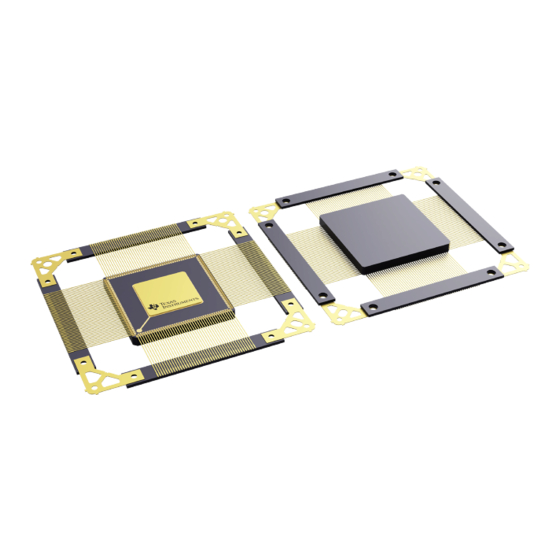
Page 14: Die Layout
COMPOSITI COORDINATES THICKNESS FINISH POTENTIAL 219.4 x 207.0 (mils); Silicon with 55.0 x 64.0 (μm) Table 2-3 11.0 mils AlCu/TiN Ground 5572.0 x 5258.0 (μm) backgrind Introduction Copyright © 2009–2011, Texas Instruments Incorporated Submit Documentation Feedback Product Folder Link(s): SM320F2812-HT... -
Page 15: Pin Assignments
ADCINA5 V SS ADCINA4 XR/W ADCINA3 PWM12 ADCINA2 PWM11 ADCINA1 PWM10 ADCINA0 PWM9 ADCLO PWM8 V SSAIO PWM7 Figure 2-2. SM320F2812 172-Pin HFG CQFP (Top View) Introduction Copyright © 2009–2011, Texas Instruments Incorporated Submit Documentation Feedback Product Folder Link(s): SM320F2812-HT... -
Page 16: Signal Descriptions
8 mA. (2) I = Input, O = Output, Z = High impedance (3) PU = pin has internal pullup; PD = pin has internal pulldown Introduction Copyright © 2009–2011, Texas Instruments Incorporated Submit Documentation Feedback Product Folder Link(s): SM320F2812-HT... - Page 17 1. XREADY 42.6 1972.4 XREADY can be configured to be a synchronous or an asynchronous input. See the timing diagrams for more details. Introduction Copyright © 2009–2011, Texas Instruments Incorporated Submit Documentation Feedback Product Folder Link(s): SM320F2812-HT...
- Page 18 5361.5 2522.3 – devices, TEST1 must be left unconnected. Test Pin. Reserved for TI. On F281x TEST2 5361.5 2436.1 – devices, TEST2 must be left unconnected. Introduction Copyright © 2009–2011, Texas Instruments Incorporated Submit Documentation Feedback Product Folder Link(s): SM320F2812-HT...
- Page 19 EMU1 42.6 3430.9 I/O/Z the emulator system and is defined as input/output through the JTAG scan. Introduction Copyright © 2009–2011, Texas Instruments Incorporated Submit Documentation Feedback Product Folder Link(s): SM320F2812-HT...
- Page 20 ADC Digital GND 42.6 1901.0 ADC Digital 1.8-V (or 1.9-V) Supply 211.5 42.6 3.3-V Analog I/O Power Pin DDAIO 42.6 204.3 Analog I/O Ground Pin SSAIO Introduction Copyright © 2009–2011, Texas Instruments Incorporated Submit Documentation Feedback Product Folder Link(s): SM320F2812-HT...
- Page 21 2732.4 DD3VFL have been met. This pin is used as VDDIO in ROM parts and must be connected to 3.3 V in ROM parts as well. Introduction Copyright © 2009–2011, Texas Instruments Incorporated Submit Documentation Feedback Product Folder Link(s): SM320F2812-HT...
- Page 22 (1) Typical drive strength of the output buffer for all pins [except TDO, XCLKOUT, XF, XINTF, EMU0, and EMU1 pins] is 4 mA typical. (2) I = Input, O = Output, Z = High impedance (3) PU = pin has internal pullup; PD = pin has internal pulldown Introduction Copyright © 2009–2011, Texas Instruments Incorporated Submit Documentation Feedback Product Folder Link(s): SM320F2812-HT...
- Page 23 GPIO or SCI GPIOF4 SCITXDA (O) 42.6 2565.1 I/O/Z asynchronous serial port TX data GPIO or SCI GPIOF5 SCIRXDA (I) 42.6 2361.3 I/O/Z asynchronous serial port RX data Introduction Copyright © 2009–2011, Texas Instruments Incorporated Submit Documentation Feedback Product Folder Link(s): SM320F2812-HT...
- Page 24 NOTE Other than the power supply pins, no pin should be driven before the 3.3-V rail has reached recommended operating conditions. Introduction Copyright © 2009–2011, Texas Instruments Incorporated Submit Documentation Feedback Product Folder Link(s): SM320F2812-HT...
-
Page 25: Functional Overview
Peripheral Bus † 45 of the possible 96 interrupts are used on the device. ‡ Protected by the code-security module. Figure 3-1. Functional Block Diagram Functional Overview Copyright © 2009–2011, Texas Instruments Incorporated Submit Documentation Feedback Product Folder Link(s): SM320F2812-HT... -
Page 26: Memory Map
Zones 0 and 1 and Zones 6 and 7 share the same chip select; hence, these memory blocks have mirrored locations. Figure 3-2. F2812 Memory Map (See Notes A. Through G.) Functional Overview Copyright © 2009–2011, Texas Instruments Incorporated Submit Documentation Feedback Product Folder Link(s):... -
Page 27: Addresses Of Flash Sectors In F2812
On the F2812, at reset, XINTF Zone 7 is accessed if the XMP/MC pin is pulled high. This signal selects microprocessor or microcomputer mode of operation. In microprocessor mode, Zone 7 is mapped to high Functional Overview Copyright © 2009–2011, Texas Instruments Incorporated Submit Documentation Feedback Product Folder Link(s):... -
Page 28: Wait States
1-wait Fixed Programmed via the XINTF registers. Programmable, XINTF Cycles can be extended by external memory or peripheral. 1-wait minimum 0-wait operation is not possible. Functional Overview Copyright © 2009–2011, Texas Instruments Incorporated Submit Documentation Feedback Product Folder Link(s): SM320F2812-HT... -
Page 29: Brief Descriptions
Fetches 3.2.3 Peripheral Bus To enable migration of peripherals between various Texas Instruments (TI) DSP families, the F2812 adopts a peripheral bus standard for peripheral interconnect. The peripheral bus bridge multiplexes the various busses that make up the processor Memory Bus into a single bus consisting of 16 address lines and 16 or 32 data lines and associated control signals. -
Page 30: External Interface (Xintf)
Table 3-3 shows the details of how various boot modes may be invoked. See the TMS320x281x DSP Boot ROM Reference Guide (SPRS095), for more information. Functional Overview Copyright © 2009–2011, Texas Instruments Incorporated Submit Documentation Feedback Product Folder Link(s): SM320F2812-HT... -
Page 31: Security
(either ROM or Flash) and is warranted by Texas Instruments (TI), in accordance with its standard terms and conditions, to conform to TI’s published specifications for the warranty period applicable for this device. -
Page 32: Peripheral Interrupt Expansion (Pie) Block
Turn off clock to CPU and peripherals. This mode leaves the oscillator and PLL functional. An external interrupt event wakes the processor and the peripherals. Execution begins on the next valid cycle after detection of the interrupt event. Functional Overview Copyright © 2009–2011, Texas Instruments Incorporated Submit Documentation Feedback Product Folder Link(s): SM320F2812-HT... -
Page 33: Peripheral Frames 0, 1, 2 (Pfn)
240x devices (with some minor enhancements). ADC: The ADC block is a 12-bit converter, single ended, 16-channels. It contains two sample-and-hold units for simultaneous sampling. Functional Overview Copyright © 2009–2011, Texas Instruments Incorporated Submit Documentation Feedback Product Folder Link(s): SM320F2812-HT... -
Page 34: Serial Port Peripherals
Peripheral Frame 1: These are peripherals that are mapped to the 32-bit peripheral bus. Table 3-5. • Peripheral Frame 2: These are peripherals that are mapped to the 16-bit peripheral bus. Table 3-6. Functional Overview Copyright © 2009–2011, Texas Instruments Incorporated Submit Documentation Feedback Product Folder Link(s): SM320F2812-HT... -
Page 35: Peripheral Frame 0 Registers
0x00 6200 reserved 3584 0x00 6FFF (1) The eCAN control registers only support 32-bit read/write operations. All 32-bit accesses are aligned to even address boundaries. Functional Overview Copyright © 2009–2011, Texas Instruments Incorporated Submit Documentation Feedback Product Folder Link(s): SM320F2812-HT... -
Page 36: Peripheral Frame 2 Registers
0x00 7840 reserved 1984 0x00 7FFF (1) Peripheral Frame 2 only allows 16-bit accesses. All 32-bit accesses are ignored (invalid data may be returned or written). Functional Overview Copyright © 2009–2011, Texas Instruments Incorporated Submit Documentation Feedback Product Folder Link(s): SM320F2812-HT... -
Page 37: Device Emulation Registers
The external interface is a non-multiplexed asynchronous bus, similar to the C240x external interface. The external interface on the F2812 is mapped into five fixed zones shown in Figure 3-3. Figure 3-3 shows the F2812 XINTF signals. Functional Overview Copyright © 2009–2011, Texas Instruments Incorporated Submit Documentation Feedback Product Folder Link(s): SM320F2812-HT... -
Page 38: External Interface Block Diagram
XZCS6AND7 is dually mapped to both Zones 6 and Zone 7. This means that if Zone 7 is disabled (via the MP/MC mode) then any external memory is still accessible via Zone 6 address space. Figure 3-3. External Interface Block Diagram Functional Overview Copyright © 2009–2011, Texas Instruments Incorporated Submit Documentation Feedback Product Folder Link(s): SM320F2812-HT... -
Page 39: Timing Registers
Table 3-9. XREVISION Register Bit Definitions BIT(S) NAME TYPE RESET DESCRIPTION Current XINTF Revision. For internal use/reference. Test purposes only. 15-0 REVISION 0x0004 Subject to change. Functional Overview Copyright © 2009–2011, Texas Instruments Incorporated Submit Documentation Feedback Product Folder Link(s): SM320F2812-HT... -
Page 40: Interrupts
Eight PIE block interrupts are grouped into one CPU interrupt. In total, 12 CPU interrupt groups, with 8 interrupts per group equals 96 possible interrupts. On the F2812, 45 of these are used by peripherals as shown in Table 3-10. Functional Overview Copyright © 2009–2011, Texas Instruments Incorporated Submit Documentation Feedback Product Folder Link(s): SM320F2812-HT... -
Page 41: Multiplexing Of Interrupts Using The Pie Block
(1) Out of the 96 possible interrupts, 45 interrupts are currently used. the remaining interrupts are reserved for future devices. However, these interrupts can be used as software interrupts if they are enabled at the PIEIFRx level. Functional Overview Copyright © 2009–2011, Texas Instruments Incorporated Submit Documentation Feedback Product Folder Link(s):... -
Page 42: Pie Configuration And Control Registers
PIE, INT12 Group Flag Register 0x0000-0CFA Reserved Reserved 0x0000-0CFF (1) The PIE configuration and control registers are not protected by EALLOW mode. The PIE vector table is protected. Functional Overview Copyright © 2009–2011, Texas Instruments Incorporated Submit Documentation Feedback Product Folder Link(s): SM320F2812-HT... -
Page 43: External Interrupts
Each external interrupt can be enabled/disabled or qualified using positive or negative going edge. For more information, see the TMS320x281x System Control and Interrupts Reference Guide (SPRU078). Functional Overview Copyright © 2009–2011, Texas Instruments Incorporated Submit Documentation Feedback Product Folder Link(s):... -
Page 44: System Control
CLKIN is the clock input to the CPU. SYSCLKOUT is the output clock of the CPU. They are of the same frequency. Figure 3-6. Clock and Reset Domains Functional Overview Copyright © 2009–2011, Texas Instruments Incorporated Submit Documentation Feedback Product Folder Link(s):... -
Page 45: Pll, Clocking, Watchdog, And Low-Power Mode Registers
(2) The PLL control register (PLLCR) is reset to a known state by the XRS signal only. Emulation reset (through Code Composer Studio) does not reset PLLCR. Functional Overview Copyright © 2009–2011, Texas Instruments Incorporated Submit Documentation Feedback Product Folder Link(s):... -
Page 46: Osc And Pll Block
(1) The PLLCR register is reset to a known state by the XRS reset line. If a reset is issued by the debugger, the PLL clocking ratio is not changed. Functional Overview Copyright © 2009–2011, Texas Instruments Incorporated Submit Documentation Feedback Product Folder Link(s):... -
Page 47: Loss Of Input Clock
The typical specifications for the external quartz crystal for a frequency of 30 MHz are listed below: • Fundamental mode, parallel resonant • (load capacitance) = 12 pF Functional Overview Copyright © 2009–2011, Texas Instruments Incorporated Submit Documentation Feedback Product Folder Link(s): SM320F2812-HT... -
Page 48: Watchdog Block
In IDLE mode, the WDINT signal can generate an interrupt to the CPU, via the PIE, to take the CPU out of IDLE mode. In HALT mode, this feature cannot be used because the oscillator (and PLL) are turned off and hence so is the WATCHDOG. Functional Overview Copyright © 2009–2011, Texas Instruments Incorporated Submit Documentation Feedback Product Folder Link(s): SM320F2812-HT... -
Page 49: Low-Power Modes Block
The low-power modes do not affect the state of the output pins (PWM pins included). They are in whatever state the code left them in when the IDLE instruction was executed. Functional Overview Copyright © 2009–2011, Texas Instruments Incorporated Submit Documentation Feedback Product Folder Link(s):... -
Page 50: Peripherals
16-Bit Timer Divide-Down 32-Bit Timer Period TDDRH:TDDR PRDH:PRD 16-Bit Prescale Counter SYSCLKOUT PSCH:PSC TCR.4 32-Bit Counter (Timer Start Status) Borrow TIMH:TIM Borrow TINT Figure 4-1. CPU-Timers Peripherals Copyright © 2009–2011, Texas Instruments Incorporated Submit Documentation Feedback Product Folder Link(s): SM320F2812-HT... -
Page 51: Cpu-Timer Interrupts Signals And Output Signal (See Notes A. And B.)
C28x. When the counter reaches 0, a timer interrupt output signal generates an interrupt pulse. The registers listed in Table 4-1 are used to configure the timers. For more information, see the TMS320x281x System Control and Interrupts Reference Guide (SPRU078). Peripherals Copyright © 2009–2011, Texas Instruments Incorporated Submit Documentation Feedback Product Folder Link(s): SM320F2812-HT... -
Page 52: Cpu-Timers 0, 1, 2 Configuration And Control Registers
CPU-Timer 2, Control Register reserved 0x00 0C15 TIMER2TPR 0x00 0C16 CPU-Timer 2, Prescale Register TIMER2TPRH 0x00 0C17 CPU-Timer 2, Prescale Register High 0x00 0C18 reserved 0x00 0C3F Peripherals Copyright © 2009–2011, Texas Instruments Incorporated Submit Documentation Feedback Product Folder Link(s): SM320F2812-HT... -
Page 53: Event Manager Modules (Eva, Evb)
C6TRIP T1CTRIP_PDPINTA T3CTRIP_PDPINTB External Trip Inputs T4CTRIP/EVBSOC T2CTRIP/EVASOC (1) In the 24x/240x-compatible mode, the T1CTRIP_PDPINTA pin functions as PDPINTA and the T3CTRIP_PDPINTB pin functions as PDPINTB. Peripherals Copyright © 2009–2011, Texas Instruments Incorporated Submit Documentation Feedback Product Folder Link(s): SM320F2812-HT... -
Page 54: Eva Registers
(1) The EV-B register set is identical except the address range is from 0x00–7500 to 0x00–753F. The above registers are mapped to Zone 2. This space allows only 16-bit accesses. 32-bit accesses produce undefined results. (2) New register compared to 24x/240x Peripherals Copyright © 2009–2011, Texas Instruments Incorporated Submit Documentation Feedback Product Folder Link(s): SM320F2812-HT... - Page 55 Capture Units CAP3_QEPI1 Index Qual CAPCONA(15:12,7:0) EXTCONA(1:2) The EVB module is similar to the EVA module. Figure 4-3. Event Manager A Functional Block Diagram (See Note A.) Peripherals Copyright © 2009–2011, Texas Instruments Incorporated Submit Documentation Feedback Product Folder Link(s): SM320F2812-HT...
-
Page 56: General-Purpose (Gp) Timers
The reload condition that supports double update PWM mode is reloaded on Underflow (beginning of PWM period) OR Period (middle of PWM period). Double update PWM mode can be achieved by using this condition for compare value reload. Peripherals Copyright © 2009–2011, Texas Instruments Incorporated Submit Documentation Feedback Product Folder Link(s): SM320F2812-HT... -
Page 57: Pwm Characteristics
4.2.9 External ADC Start-of-Conversion EVA/EVB start-of-conversion (SOC) can be sent to an external pin (EVASOC/EVBSOC) for external ADC interface. EVASOC and EVBSOC are MUXed with T2CTRIP and T4CTRIP, respectively. Peripherals Copyright © 2009–2011, Texas Instruments Incorporated Submit Documentation Feedback Product Folder Link(s): SM320F2812-HT... -
Page 58: Enhanced Analog-To-Digital Converter (Adc) Module
Autosequencing allows the system to convert the same channel multiple times, allowing the user to perform oversampling algorithms. This gives increased resolution over traditional single-sampled conversion results. Peripherals Copyright © 2009–2011, Texas Instruments Incorporated Submit Documentation Feedback Product Folder Link(s): SM320F2812-HT... -
Page 59: Block Diagram Of The F2812 Adc Module
ADC module is powered. If high, the ADC module goes into low-power mode. The HALT mode stops the clock to the CPU, which stops the HSPCLK. Therefore the ADC register logic is turned off indirectly. Peripherals Copyright © 2009–2011, Texas Instruments Incorporated Submit Documentation Feedback Product Folder Link(s): SM320F2812-HT... -
Page 60: Adc Pin Connections With Internal Reference (See Notes A And B)
Figure 4-5. ADC Pin Connections With Internal Reference (See Notes A and B) NOTE The temperature rating of any recommended component must match the rating of the end product. Peripherals Copyright © 2009–2011, Texas Instruments Incorporated Submit Documentation Feedback Product Folder Link(s): SM320F2812-HT... -
Page 61: Adc Pin Connections With External Reference
ADCREFP and ADCREFM. See the TMS320x281x DSP Analog-to-Digital Converter (ADC) Reference Guide (literature number SPRU060) for more information. Figure 4-6. ADC Pin Connections With External Reference Peripherals Copyright © 2009–2011, Texas Instruments Incorporated Submit Documentation Feedback Product Folder Link(s): SM320F2812-HT... -
Page 62: Adc Registers
0x00 7118 ADC Control Register 3 ADCST 0x00 7119 ADC Status Register 0x00 711C reserved 0x00 711F (1) The above registers are Peripheral Frame 2 Registers. Peripherals Copyright © 2009–2011, Texas Instruments Incorporated Submit Documentation Feedback Product Folder Link(s): SM320F2812-HT... -
Page 63: Enhanced Controller Area Network (Ecan) Module
For a SYSCLKOUT of 150 MHz, the smallest bit rate possible is 23.4 kbps. The 28x CAN has passed the conformance test per ISO/DIS 16845. Contact TI for further details. Peripherals Copyright © 2009–2011, Texas Instruments Incorporated Submit Documentation Feedback Product Folder Link(s):... -
Page 64: Ecan Block Diagram And Interface Circuit
–40°C to 125°C Standby & Sleep – –40°C to 125°C SN65HVD234 3.3 V Adjustable None SN65HVD235 3.3 V Standby Adjustable None Autobaud Loopback –40°C to 125°C Peripherals Copyright © 2009–2011, Texas Instruments Incorporated Submit Documentation Feedback Product Folder Link(s): SM320F2812-HT... -
Page 65: Ecan Memory Map
Message Identifier − MSGID 61E8h−61E9h Message Control − MSGCTRL 61EAh−61EBh 61ECh−61EDh Message Data Low − MDL 61EEh−61EFh Message Data High − MDH Figure 4-8. eCAN Memory Map Peripherals Copyright © 2009–2011, Texas Instruments Incorporated Submit Documentation Feedback Product Folder Link(s): SM320F2812-HT... -
Page 66: Can Registers Map
0x00 6030 Time-out control (Reserved in SCC mode) CANTOS 0x00 6032 Time-out status (Reserved in SCC mode) (1) These registers are mapped to Peripheral Frame 1. Peripherals Copyright © 2009–2011, Texas Instruments Incorporated Submit Documentation Feedback Product Folder Link(s): SM320F2812-HT... -
Page 67: Multichannel Buffered Serial Port (Mcbsp) Module
(2) Serial port performance is limited by I/O buffer switching speed. Internal prescalers must be adjusted such that the peripheral speed is less than the I/O buffer speed limit—20-MHz maximum. Peripherals Copyright © 2009–2011, Texas Instruments Incorporated Submit Documentation Feedback Product Folder Link(s):... -
Page 68: Mcbsp Module With Fifo
RX FIFO _1 RX Interrupt Logic MRINT Interrupt RX FIFO _0 RX FIFO _0 To CPU RX FIFO Registers Peripheral Read Bus Figure 4-9. McBSP Module With FIFO Peripherals Copyright © 2009–2011, Texas Instruments Incorporated Submit Documentation Feedback Product Folder Link(s): SM320F2812-HT... -
Page 69: Mcbsp Register Summary
XCERH 0x0000 McBSP Transmit Channel Enable Register Partition H (1) DRR2/DRR1 and DXR2/DXR1 share the same addresses of receive and transmit FIFO registers in FIFO mode. Peripherals Copyright © 2009–2011, Texas Instruments Incorporated Submit Documentation Feedback Product Folder Link(s): SM320F2812-HT... - Page 70 0x0000 McBSP FIFO Interrupt Register MFFST 0x0000 McBSP FIFO Status Register (1) FIFO pointers advancing is based on order of access to DRR2/DRR1 and DXR2/DXR1 registers. Peripherals Copyright © 2009–2011, Texas Instruments Incorporated Submit Documentation Feedback Product Folder Link(s): SM320F2812-HT...
-
Page 71: Serial Communications Interface (Sci) Module
9.375 10 b / s ´ ´ • • NRZ (non-return-to-zero) format • Ten SCI module control registers located in the control register frame beginning at address 7050h Peripherals Copyright © 2009–2011, Texas Instruments Incorporated Submit Documentation Feedback Product Folder Link(s): SM320F2812-HT... -
Page 72: Sci-A Registers
(1) Shaded registers are new registers for the FIFO mode. (2) Registers in this table are mapped to peripheral bus 16 space. This space only allows 16-bit accesses. 32-bit accesses produce undefined results. Peripherals Copyright © 2009–2011, Texas Instruments Incorporated Submit Documentation Feedback Product Folder Link(s): SM320F2812-HT... -
Page 73: Serial Communications Interface (Sci) Module Block Diagram
SCIFFRX.15 RX Error FE OE RX Error RX ERR INT ENA SCI RX Interrupt select logic SCICTL1.6 Figure 4-10. Serial Communications Interface (SCI) Module Block Diagram Peripherals Copyright © 2009–2011, Texas Instruments Incorporated Submit Documentation Feedback Product Folder Link(s): SM320F2812-HT... -
Page 74: Serial Peripheral Interface (Spi) Module
When a register is accessed, the register data is in the lower byte (7–0), and the upper byte (15–8) is read as zeros. Writing to the upper byte has no effect. Peripherals Copyright © 2009–2011, Texas Instruments Incorporated Submit Documentation Feedback Product Folder Link(s):... -
Page 75: Spi Registers
0x00 704F SPI Priority Control Register (1) The above registers are mapped to Peripheral Frame 2. This space only allows 16-bit accesses. 32-bit accesses produce undefined results. Peripherals Copyright © 2009–2011, Texas Instruments Incorporated Submit Documentation Feedback Product Folder Link(s): SM320F2812-HT... -
Page 76: Serial Peripheral Interface Module Block Diagram (Slave Mode)
SPICLK SPIBRR.6 − 0 † SPISTE is driven low by the master for a slave device. Figure 4-11. Serial Peripheral Interface Module Block Diagram (Slave Mode) Peripherals Copyright © 2009–2011, Texas Instruments Incorporated Submit Documentation Feedback Product Folder Link(s): SM320F2812-HT... -
Page 77: Gpio Mux
I/O signals (via the GPxTOGGLE registers), or for reading/writing to the individual I/O signals (via the GPxDAT registers). Table 4-12 lists the GPIO Data Registers. For more information, see the TMS320x281x System Control and Interrupts Reference Guide (SPRU078). Peripherals Copyright © 2009–2011, Texas Instruments Incorporated Submit Documentation Feedback Product Folder Link(s): SM320F2812-HT... -
Page 78: Gpio Data Registers
(1) Reserved location returns undefined values and writes are ignored. (2) These registers are NOT EALLOW protected. The above registers are typically accessed regularly by the user. Peripherals Copyright © 2009–2011, Texas Instruments Incorporated Submit Documentation Feedback Product Folder Link(s):... -
Page 79: Gpio/Peripheral Pin Multiplexing
The CxTRIP and TxCTRIP pins also put the corresponding PWM pins in high impedance, if they are driven low (as GPIO pins) and bit EXTCONx.0 = 1. Peripherals Copyright © 2009–2011, Texas Instruments Incorporated Submit Documentation Feedback Product Folder Link(s):... -
Page 80: Development Support
Development Support Texas Instruments (TI) offers an extensive line of development tools for the C28x™ generation of DSPs, including tools to evaluate the performance of the processors, generate code, develop algorithm implementations, and fully integrate and debug software and hardware modules. -
Page 81: Documentation Support
TMS320x281x System Control and Interrupts Reference Guide (SPRU078) describes the various interrupts and system control features of the 281x digital signal processors (DSPs). Development Support Copyright © 2009–2011, Texas Instruments Incorporated Submit Documentation Feedback Product Folder Link(s): SM320F2812-HT... - Page 82 In addition, software techniques such as Random PWM method can be used by special features of the Texas Instruments (TI) TMS320x24xx DSP controllers to significantly reduce noise effects caused by EMI radiation.
- Page 83 To send comments regarding this TMS320F281x/TMS320C281x data manual (SPRS174), use the commentsatbooks.sc.ti.com email address, which is a repository for feedback. For questions and support, contact the Product Information Center listed at http://www.ti.com/sc/docs/pic/home.htm. Development Support Copyright © 2009–2011, Texas Instruments Incorporated Submit Documentation Feedback Product Folder Link(s): SM320F2812-HT...
-
Page 84: Electrical Specifications
(1) Continuous clamp current per pin is ±2 mA (2) Long-term high-temperature storage and/or extended use at maximum temperature conditions may result in a reduction of overall device life. Electrical Specifications Copyright © 2009–2011, Texas Instruments Incorporated Submit Documentation Feedback Product Folder Link(s): SM320F2812-HT... -
Page 85: Recommended Operating Conditions
(2) The following pins have no internal PU/PD: GPIOE0, GPIOE1, GPIOF0, GPIOF1, GPIOF2, GPIOF3, GPIOF12, GPIOG4, and GPIOG5. (3) The following pins have an internal pulldown: XMP/MC, TESTSEL, and TRST. Electrical Specifications Copyright © 2009–2011, Texas Instruments Incorporated Submit Documentation Feedback Product Folder Link(s):... -
Page 86: Sm320F2812-Ht Life Expectancy Curve
1. See data sheet for absolute maximum and minimum recommended operating conditions. 2. Silicon operating life design goal is 10 years at 105°C junction temperature (does not include package interconnect life). Electrical Specifications Copyright © 2009–2011, Texas Instruments Incorporated Submit Documentation Feedback Product Folder Link(s): SM320F2812-HT... -
Page 87: Current Consumption By Power-Supply Pins Over Recommended Operating Conditions During Low-Power Modes At 150-Mhz Sysclkout
(2) MAX numbers are at 125°C, and max voltage (V = 2.0 V; V = 3.6 V). DDIO DD3VFL NOTE HALT and STANDBY modes cannot be used when the PLL is disabled. Electrical Specifications Copyright © 2009–2011, Texas Instruments Incorporated Submit Documentation Feedback Product Folder Link(s): SM320F2812-HT... -
Page 88: Current Consumption Graphs
. It includes a trivial amount of current (<1 mA) drawn by DDIO DD3VFL VDDAIO. Figure 6-2. Typical Current Consumption Over Frequency SYSCLKOUT (MHz) TOTAL POWER Figure 6-3. Typical Power Consumption Over Frequency Electrical Specifications Copyright © 2009–2011, Texas Instruments Incorporated Submit Documentation Feedback Product Folder Link(s): SM320F2812-HT... -
Page 89: Reducing Current Consumption
(with the aid of additional external components) may be used to meet the power sequencing requirement. See www.spectrumdigital.com for F2812 eZdsp™ schematics and updates. Table 6-2. Recommended Low-Dropout Regulators SUPPLIER PART NUMBER Texas Instruments TPS767D301 Electrical Specifications Copyright © 2009–2011, Texas Instruments Incorporated Submit Documentation Feedback Product Folder Link(s): SM320F2812-HT... -
Page 90: F2812 Typical Power-Up And Power-Down Sequence - Option 2
The GPIO pins are undefined until V = 1 V and V = 2.5 V. DDIO See Figure 6-8, Figure 6-4. F2812 Typical Power-Up and Power-Down Sequence – Option 2 Electrical Specifications Copyright © 2009–2011, Texas Instruments Incorporated Submit Documentation Feedback Product Folder Link(s): SM320F2812-HT... -
Page 91: Signal Transition Levels
10% of the total voltage range and higher and the level at which the input is said to be high is 90% of the total voltage range and higher. NOTE See the individual timing diagrams for levels used for testing timing parameters. Electrical Specifications Copyright © 2009–2011, Texas Instruments Incorporated Submit Documentation Feedback Product Folder Link(s): SM320F2812-HT... -
Page 92: Timing Parameter Symbology
Input requirements in this data sheet are tested with an input slew rate of < 4 Volts per nanosecond (4 V/ns) at the device pin. Figure 6-7. 3.3-V Test Load Circuit Electrical Specifications Copyright © 2009–2011, Texas Instruments Incorporated Submit Documentation Feedback Product Folder Link(s):... -
Page 93: Device Clock Table
Table 6-4. Input Clock Frequency PARAMETER UNIT Resonator Input clock frequency Crystal XCLKIN Limp mode clock frequency (1) Not production tested. > 125°C. (2) Not guaranteed for T Electrical Specifications Copyright © 2009–2011, Texas Instruments Incorporated Submit Documentation Feedback Product Folder Link(s): SM320F2812-HT... -
Page 94: Output Clock Characteristics
(3) The PLL must be used for maximum frequency operation. (4) Not production tested. (5) This parameter has changed from 4096 XCLKIN cycles in the earlier revisions of the silicon. Electrical Specifications Copyright © 2009–2011, Texas Instruments Incorporated Submit Documentation Feedback Product Folder Link(s): SM320F2812-HT... -
Page 95: Reset Timing
(4) The boot ROM reads the password locations. Therefore, this timing requirement includes the wakeup time for flash. See the TMS320x281x Boot ROM Reference Guide (SPRU095) and TMS320x281x System Control and Interrupts Reference Guide (SPRU078) for further information. Electrical Specifications Copyright © 2009–2011, Texas Instruments Incorporated Submit Documentation Feedback Product Folder Link(s): SM320F2812-HT... - Page 96 SYSCLKOUT speed. The SYSCLKOUT is based on user environment and could be with or without PLL enabled. Figure 6-9. Power-on Reset in Microcomputer Mode (XMP/MC = 0) (See Note A) Electrical Specifications Copyright © 2009–2011, Texas Instruments Incorporated Submit Documentation Feedback Product Folder Link(s):...
-
Page 97: Power-On Reset In Microcomputer Mode (Xmp/Mc = 0) (See Note A)
B. The state of the GPIO pins is undefined (i.e., they could be input or output) until the 1.8-V (or 1.9-V) supply reaches at least 1 V and 3.3-V supply reaches 2.5 V.. Figure 6-10. Power-on Reset in Microprocessor Mode (XMP/MC = 1) Electrical Specifications Copyright © 2009–2011, Texas Instruments Incorporated Submit Documentation Feedback Product Folder Link(s): SM320F2812-HT... -
Page 98: Power-On Reset In Microprocessor Mode (Xmp/Mc = 1)
Frequency) With the Desired Frequency. This Period (PLL Lock-up Time, t ) is 131072 XCLKIN Cycles Long.) Figure 6-12. Effect of Writing Into PLLCR Register Electrical Specifications Copyright © 2009–2011, Texas Instruments Incorporated Submit Documentation Feedback Product Folder Link(s): SM320F2812-HT... -
Page 99: Low-Power Mode Wakeup Timing
WAKE INT (see Note B) XCLKOUT = SYSCLKOUT WAKE INT can be any enabled interrupt, WDINT, XNMI, or XRS. Figure 6-13. IDLE Entry and Exit Timing Electrical Specifications Copyright © 2009–2011, Texas Instruments Incorporated Submit Documentation Feedback Product Folder Link(s): SM320F2812-HT... -
Page 100: Standby Mode Switching Characteristics
(3) This is the time taken to begin execution of the instruction that immediately follows the IDLE instruction. Execution of an ISR (triggered by the wake-up) signal involves additional latency. Electrical Specifications Copyright © 2009–2011, Texas Instruments Incorporated Submit Documentation Feedback Product Folder Link(s):... -
Page 101: Standby Entry And Exit Timing
E. After a latency period, the STANDBY mode is exited. F. Normal operation resumes. The device responds to the interrupt (if enabled). Figure 6-14. STANDBY Entry and Exit Timing Electrical Specifications Copyright © 2009–2011, Texas Instruments Incorporated Submit Documentation Feedback Product Folder Link(s): SM320F2812-HT... -
Page 102: Halt Mode Switching Characteristics
–Wake-up from flash 1125 × t Cycles d(wake) c(SCO –Flash module in sleep state –Wake-up from SARAM 35 × t Cycles c(SCO) (1) Not production tested. Electrical Specifications Copyright © 2009–2011, Texas Instruments Incorporated Submit Documentation Feedback Product Folder Link(s): SM320F2812-HT... -
Page 103: Event Manager Interface
XCLKOUT = SYSCLKOUT Figure 6-15. HALT Wakeup Using XNMI 6.16 Event Manager Interface 6.16.1 PWM Timing PWM refers to all PWM outputs on EVA and EVB. Electrical Specifications Copyright © 2009–2011, Texas Instruments Incorporated Submit Documentation Feedback Product Folder Link(s): SM320F2812-HT... -
Page 104: Pwm Output Timing
(see Note A) d(PWM)XCO w(PWM) PWMx XCLKOUT = SYSCLKOUT Figure 6-16. PWM Output Timing XCLKOUT (see Note A) w(TDIR) TDIRx XCLKOUT = SYSCLKOUT Figure 6-17. TDIRx Timing Electrical Specifications Copyright © 2009–2011, Texas Instruments Incorporated Submit Documentation Feedback Product Folder Link(s): SM320F2812-HT... -
Page 105: Interrupt Timing
+ 12t d(INT) qual c(XCO) interrupt-vector fetch (1) Input Qualification Time (IQT) = [5 × QUALPRD × 2] × t c(SCO) (2) Not production tested. Electrical Specifications Copyright © 2009–2011, Texas Instruments Incorporated Submit Documentation Feedback Product Folder Link(s): SM320F2812-HT... -
Page 106: General-Purpose Input/Output (Gpio) - Output Timing
Rise time, GPIO switching low to high All GPIOs r(GPO) Fall time, GPIO switching high to low All GPIOs f(GPO) Toggling frequency, GPO pins (1) Not production tested. Electrical Specifications Copyright © 2009–2011, Texas Instruments Incorporated Submit Documentation Feedback Product Folder Link(s): SM320F2812-HT... -
Page 107: General-Purpose Input/Output (Gpio) - Input Timing
With qualifier 1 × t + IQT c(SCO) (1) Not production tested. (2) Input Qualification Time (IQT) = [5 × QUALPRD × 2] × t c(SCO) Electrical Specifications Copyright © 2009–2011, Texas Instruments Incorporated Submit Documentation Feedback Product Folder Link(s): SM320F2812-HT... -
Page 108: Spi Master Mode Timing
(SPIBRR ) 1) (3) Not production tested. (4) The active edge of the SPICLK signal referenced is controlled by the CLOCK POLARITY bit (SPICCR.6). Electrical Specifications Copyright © 2009–2011, Texas Instruments Incorporated Submit Documentation Feedback Product Folder Link(s): SM320F2812-HT... -
Page 109: Spi Master Mode External Timing (Clock Phase = 0)
SPISTE will go inactive 0.5tc(SPC) after the receiving edge (SPICLK) of the last data bit. Figure 6-24. SPI Master Mode External Timing (Clock Phase = 0) Electrical Specifications Copyright © 2009–2011, Texas Instruments Incorporated Submit Documentation Feedback Product Folder Link(s):... -
Page 110: Spi Master Mode External Timing (Clock Phase = 1)
(SPIBRR ) 1) (3) Not production tested.. (4) The active edge of the SPICLK signal referenced is controlled by the CLOCK POLARITY bit (SPICCR.6). Electrical Specifications Copyright © 2009–2011, Texas Instruments Incorporated Submit Documentation Feedback Product Folder Link(s): SM320F2812-HT... -
Page 111: Spi Master External Timing (Clock Phase = 1)
SPISTE will go inactive 0.5tc(SPC) after the receiving edge (SPICLK) of the last data bit. Figure 6-25. SPI Master External Timing (Clock Phase = 1) Electrical Specifications Copyright © 2009–2011, Texas Instruments Incorporated Submit Documentation Feedback Product Folder Link(s): SM320F2812-HT... -
Page 112: Spi Slave Mode Timing
0.5tc(SPC) after the receiving edge (SPICLK) of the last data bit. Figure 6-26. SPI Slave Mode External Timing (Clock Phase = 0) Electrical Specifications Copyright © 2009–2011, Texas Instruments Incorporated Submit Documentation Feedback Product Folder Link(s):... -
Page 113: Spi Slave Mode External Timing (Clock Phase = 0)
(4) The active edge of the SPICLK signal referenced is controlled by the CLOCK POLARITY bit (SPICCR.6). (5) The active edge of the SPICLK signal referenced is controlled by the CLOCK POLARITY bit (SPICCR.6). Electrical Specifications Copyright © 2009–2011, Texas Instruments Incorporated Submit Documentation Feedback Product Folder Link(s):... -
Page 114: External Interface (Xintf) Timing
• If the XREADY signal is ignored (USEREADY = 0), then: 1. Lead: LR ≥ t c(XTIM) Electrical Specifications Copyright © 2009–2011, Texas Instruments Incorporated Submit Documentation Feedback Product Folder Link(s): SM320F2812-HT... -
Page 115: Xtiming Register Configuration Restrictions
• If the XREADY signal is sampled in the Asynchronous mode (USEREADY = 1, READYMODE = 1), then: 1. Lead: LR ≥ t c(XTIM) LW ≥ t c(XTIM) Electrical Specifications Copyright © 2009–2011, Texas Instruments Incorporated Submit Documentation Feedback Product Folder Link(s): SM320F2812-HT... -
Page 116: Xtiming Register Configuration Restrictions
Table 6-33. XINTF Clock Configurations MODE SYSCLKOUT XTIMCLK XCLKOUT SYSCLKOUT SYSCLKOUT Example: 150 MHz 150 MHz 150 MHz SYSCLKOUT 1/2 SYSCLKOUT Example: 150 MHz 150 MHz 75 MHz Electrical Specifications Copyright © 2009–2011, Texas Instruments Incorporated Submit Documentation Feedback Product Folder Link(s): SM320F2812-HT... -
Page 117: Relationship Between Xtimclk And Sysclkout
XBANK SYSCLKOUT XCLKOUT C28x † XTIMCLK † XINTCNF2 XINTCNF2 (CLKOFF) XINTCNF2 (XTIMCLK) (CLKMODE) † Default Value after reset Figure 6-28. Relationship Between XTIMCLK and SYSCLKOUT Electrical Specifications Copyright © 2009–2011, Texas Instruments Incorporated Submit Documentation Feedback Product Folder Link(s): SM320F2812-HT... -
Page 118: Xintf Signal Alignment To Xclkout
+ trail XTIMCLK cycles (including hardware waitstates) is odd, then the alignment is with respect to the falling edge of XCLKOUT. Examples: XZCSH Zone chip-select inactive high XRNWH XR/W inactive high Electrical Specifications Copyright © 2009–2011, Texas Instruments Incorporated Submit Documentation Feedback Product Folder Link(s): SM320F2812-HT... -
Page 119: External Interface Read Timing
C. For USEREADY = 0, the external XREADY input signal is ignored. D. XA[0:18] holds the last address put on the bus during inactive cycles, including alignment cycles. Figure 6-29. Example Read Access Electrical Specifications Copyright © 2009–2011, Texas Instruments Incorporated Submit Documentation Feedback Product Folder Link(s): SM320F2812-HT... -
Page 120: External Interface Write Timing
C. For USEREADY = 0, the external XREADY input signal is ignored. D. XA[0:18] holds the last address put on the bus during inactive cycles, including alignment cycles. Figure 6-30. Example Write Access Electrical Specifications Copyright © 2009–2011, Texas Instruments Incorporated Submit Documentation Feedback Product Folder Link(s): SM320F2812-HT... -
Page 121: Example Write Access
XTIMING register parameters used for this example: XRDLEAD XRDACTIVE XRDTRAIL USEREADY X2TIMING XWRLEAD XWRACTIVE XWRTRAIL READYMODE ≥ 1 ≥ 0 ≥ 0 (1) N/A = "Don't care" for this example Electrical Specifications Copyright © 2009–2011, Texas Instruments Incorporated Submit Documentation Feedback Product Folder Link(s): SM320F2812-HT... -
Page 122: External Interface Ready-On-Read Timing With One External Wait State
D = (XRDLEAD + XRDACTIVE – 3 + n) t – t c(XTIM) su(XRDYasynchL)XCOHL where n is the sample number: n = 1, 2, 3, and so forth. Electrical Specifications Copyright © 2009–2011, Texas Instruments Incorporated Submit Documentation Feedback Product Folder Link(s): SM320F2812-HT... -
Page 123: Example Read With Synchronous Xready Access
XRDLEAD XRDACTIVE XRDTRAIL USEREADY X2TIMING XWRLEAD XWRACTIVE XWRTRAIL READYMODE 0 = XREADY ≥ 1 ≥ 1 (Synch) (1) N/A = "Don't care" for this example Electrical Specifications Copyright © 2009–2011, Texas Instruments Incorporated Submit Documentation Feedback Product Folder Link(s): SM320F2812-HT... -
Page 124: Example Read With Asynchronous Xready Access
XRDLEAD XRDACTIVE XRDTRAIL USEREADY X2TIMING XWRLEAD XWRACTIVE XWRTRAIL READYMODE 1 = XREADY ≥ 1 ≥ 1 (Asynch) (1) N/A = "Don't care" for this example Electrical Specifications Copyright © 2009–2011, Texas Instruments Incorporated Submit Documentation Feedback Product Folder Link(s): SM320F2812-HT... -
Page 125: External Interface Ready-On-Write Timing With One External Wait State
D = (XWRLEAD + XWRACTIVE – 3 + n) t – t c(XTIM) su(XRDYasynchL)XCOHL where n is the sample number: n = 1, 2, 3, and so forth. Electrical Specifications Copyright © 2009–2011, Texas Instruments Incorporated Submit Documentation Feedback Product Folder Link(s): SM320F2812-HT... -
Page 126: Write With Synchronous Xready Access
XRDLEAD XRDACTIVE XRDTRAIL USEREADY X2TIMING XWRLEAD XWRACTIVE XWRTRAIL READYMODE 0 = XREADY ≥ 1 ≥ 1 (Synch) (1) N/A = "Don't care" for this example Electrical Specifications Copyright © 2009–2011, Texas Instruments Incorporated Submit Documentation Feedback Product Folder Link(s): SM320F2812-HT... -
Page 127: Write With Asynchronous Xready Access
XRDLEAD XRDACTIVE XRDTRAIL USEREADY X2TIMING XWRLEAD XWRACTIVE XWRTRAIL READYMODE 1 = XREADY ≥ 1 ≥ 1 (Asynch) (1) N/A = "Don't care" for this example Electrical Specifications Copyright © 2009–2011, Texas Instruments Incorporated Submit Documentation Feedback Product Folder Link(s): SM320F2812-HT... -
Page 128: Xhold And Xholda
All other signals not listed in this group remain in their default or functional operational modes during these signal events. Detailed timing diagram is released in a future revision of this data sheet. Electrical Specifications Copyright © 2009–2011, Texas Instruments Incorporated Submit Documentation Feedback Product Folder Link(s):... -
Page 129: Xhold/Xholda Timing
High-Impedance XD[15:0] Valid See Note A See Note B All pending XINTF accesses are completed. Normal XINTF operation resumes. Figure 6-35. External Interface Hold Waveform Electrical Specifications Copyright © 2009–2011, Texas Instruments Incorporated Submit Documentation Feedback Product Folder Link(s): SM320F2812-HT... -
Page 130: Xhold/Xholda Timing Requirements (Xclkout = 1/2 Xtimclk)
See Note B See Note A All pending XINTF accesses are completed. Normal XINTF operation resumes. Figure 6-36. XHOLD/XHOLDA Timing Requirements (XCLKOUT = 1/2 XTIMCLK) Electrical Specifications Copyright © 2009–2011, Texas Instruments Incorporated Submit Documentation Feedback Product Folder Link(s): SM320F2812-HT... -
Page 131: On-Chip Analog-To-Digital Converter
(2) The analog inputs have an internal clamping circuit that clamps the voltage to a diode drop above V or below V . The continuous clamp current per pin is ±2 mA. Electrical Specifications Copyright © 2009–2011, Texas Instruments Incorporated Submit Documentation Feedback Product Folder Link(s): SM320F2812-HT... -
Page 132: Adc Electrical Characteristics Over Recommended Operating Conditions
– 0.3 V applied to an analog input pin may temporarily affect the conversion of another pin. To avoid this, the analog inputs should be kept within these limits. Electrical Specifications Copyright © 2009–2011, Texas Instruments Incorporated Submit Documentation Feedback Product Folder Link(s):... -
Page 133: Current Consumption For Different Adc Configurations (At 25-Mhz Adcclk)
(3) Test Conditions: SYSCLKOUT = 150 MHz ADC module clock = 25 MHz ADC performing a continuous conversion of all 16 channels in Mode A Electrical Specifications Copyright © 2009–2011, Texas Instruments Incorporated Submit Documentation Feedback Product Folder Link(s): SM320F2812-HT... -
Page 134: Adc Power-Up Control Bit Timing
ADC results shows a higher gain. For power down, all three bits can be cleared at the same time. (2) Not production tested. Electrical Specifications Copyright © 2009–2011, Texas Instruments Incorporated Submit Documentation Feedback Product Folder Link(s): SM320F2812-HT... -
Page 135: Detailed Description
Sample and Hold SH Pulse SMODE Bit d(SH) dschx_n+1 dschx_n ADC Event Trigger from EV or Other Sources Figure 6-39. Sequential Sampling Mode (Single-Channel) Timing Electrical Specifications Copyright © 2009–2011, Texas Instruments Incorporated Submit Documentation Feedback Product Folder Link(s): SM320F2812-HT... -
Page 136: Sequential Sampling Mode (Single-Channel) Timing
Result register Delay time for successive results to (2 + Acqps) × 80 ns d(schx_n+1) appear in the Result register c(ADCCLK) (1) Not production tested. Electrical Specifications Copyright © 2009–2011, Texas Instruments Incorporated Submit Documentation Feedback Product Folder Link(s): SM320F2812-HT... -
Page 137: Simultaneous Sampling Mode (Dual-Channel) (Smode = 1)
Delay time for successive (3 + Acqps) × results to appear in Result 120 ns d(schB0_n+1) c(ADCCLK) register (1) Not production tested. Electrical Specifications Copyright © 2009–2011, Texas Instruments Incorporated Submit Documentation Feedback Product Folder Link(s): SM320F2812-HT... -
Page 138: Definitions Of Specifications And Terminology
6.29.8.8 Spurious Free Dynamic Range (SFDR) SFDR is the difference in dB between the rms amplitude of the input signal and the peak spurious signal. Electrical Specifications Copyright © 2009–2011, Texas Instruments Incorporated Submit Documentation Feedback Product Folder Link(s): SM320F2812-HT... -
Page 139: Multichannel Buffered Serial Port (Mcbsp) Timing
(4) Internal clock prescalers must be adjusted such that the McBSP clock (CLKG, CLKX, CLKR) speeds are not greater than the I/O buffer speed limit (20 MHz). Electrical Specifications Copyright © 2009–2011, Texas Instruments Incorporated Submit Documentation Feedback Product Folder Link(s):... -
Page 140: Mcbsp Switching Characteristics
(2) 2P = 1/CLKG in ns (3) Not production tested. (4) C = CLKRX low pulse width = P D = CLKRX high pulse width = P Electrical Specifications Copyright © 2009–2011, Texas Instruments Incorporated Submit Documentation Feedback Product Folder Link(s): SM320F2812-HT... -
Page 141: Mcbsp Receive Timing
(n−2) (n−3) (n−4) (XDATDLY= 00b) Bit 0 Bit (n−1) (n−2) (n−3) (XDATDLY= 01b) Bit 0 Bit (n−1) (n−2) (XDATDLY= 10b) Figure 6-42. McBSP Transmit Timing Electrical Specifications Copyright © 2009–2011, Texas Instruments Incorporated Submit Documentation Feedback Product Folder Link(s): SM320F2812-HT... -
Page 142: Mcbsp As Spi Master Or Slave Timing
Bit(n-1) (n-2) (n-3) (n-4) Bit 0 Bit(n-1) (n-2) (n-3) (n-4) Figure 6-43. McBSP Timing as SPI Master or Slave: CLKSTP = 10b, CLKXP = 0 Electrical Specifications Copyright © 2009–2011, Texas Instruments Incorporated Submit Documentation Feedback Product Folder Link(s): SM320F2812-HT... -
Page 143: Mcbsp Timing As Spi Master Or Slave: Clkstp = 11B, Clkxp
Bit(n-1) (n-2) (n-3) (n-4) Bit 0 Bit(n-1) (n-2) (n-3) (n-4) Figure 6-44. McBSP Timing as SPI Master or Slave: CLKSTP = 11b, CLKXP = 0 Electrical Specifications Copyright © 2009–2011, Texas Instruments Incorporated Submit Documentation Feedback Product Folder Link(s): SM320F2812-HT... -
Page 144: Mcbsp Timing As Spi Master Or Slave: Clkstp = 10B, Clkxp = 1
Bit(n-1) (n-2) (n-3) (n-4) Bit 0 Bit(n-1) (n-2) (n-3) (n-4) Figure 6-45. McBSP Timing as SPI Master or Slave: CLKSTP = 10b, CLKXP = 1 Electrical Specifications Copyright © 2009–2011, Texas Instruments Incorporated Submit Documentation Feedback Product Folder Link(s): SM320F2812-HT... -
Page 145: Mcbsp Timing As Spi Master Or Slave: Clkstp = 11B, Clkxp = 1
Bit(n-1) (n-2) (n-3) (n-4) Bit 0 Bit(n-1) (n-2) (n-3) (n-4) Figure 6-46. McBSP Timing as SPI Master or Slave: CLKSTP = 11b, CLKXP = 1 Electrical Specifications Copyright © 2009–2011, Texas Instruments Incorporated Submit Documentation Feedback Product Folder Link(s): SM320F2812-HT... -
Page 146: Flash Timing
(1) For 150 MHz, PAGE WS = 5 and RANDOM WS = 5 For 135 MHz, PAGE WS = 4 and RANDOM WS = 4 (2) Not production tested. Electrical Specifications Copyright © 2009–2011, Texas Instruments Incorporated Submit Documentation Feedback Product Folder Link(s): SM320F2812-HT... - Page 147 (1) Not production tested. (2) Formulas to compute page wait state and random wait state: (3) Random wait state must be greater than or equal to 1 Electrical Specifications Copyright © 2009–2011, Texas Instruments Incorporated Submit Documentation Feedback Product Folder Link(s): SM320F2812-HT...
-
Page 148: Mechanical Data
SGUS062B – JUNE 2009 – REVISED JUNE 2011 www.ti.com Mechanical Data The following mechanical package diagram(s) reflect the most current released mechanical data available for the designated device(s). Mechanical Data Copyright © 2009–2011, Texas Instruments Incorporated Submit Documentation Feedback Product Folder Link(s): SM320F2812-HT... -
Page 149: Revision History
Changes from A Revision (April 2010) to B Revision ....................Page ....• Changed Table 3.31.1 Recommended Operating Conditions to Table 6-62. Flash Endurance Timing Mechanical Data Copyright © 2009–2011, Texas Instruments Incorporated Submit Documentation Feedback Product Folder Link(s): SM320F2812-HT... - Page 150 PACKAGE OPTION ADDENDUM www.ti.com 24-Sep-2012 PACKAGING INFORMATION Orderable Device Package Type Package Pins Package Qty Lead/ Samples Status Eco Plan MSL Peak Temp Drawing Ball Finish (Requires Login) SM320F2812HFGS150 ACTIVE N / A for Pkg Type SM320F2812KGDS150A ACTIVE XCEPT Call TI N / A for Pkg Type The marketing status values are defined as follows: ACTIVE: Product device recommended for new designs.
- Page 151 PACKAGE OPTION ADDENDUM www.ti.com 24-Sep-2012 • Catalog - TI's standard catalog product Enhanced Product - Supports Defense, Aerospace and Medical Applications • Addendum-Page 2...
- Page 153 IMPORTANT NOTICE Texas Instruments Incorporated and its subsidiaries (TI) reserve the right to make corrections, enhancements, improvements and other changes to its semiconductor products and services per JESD46, latest issue, and to discontinue any product or service per JESD48, latest issue.