Table of Contents
Advertisement
Advertisement
Table of Contents

Related Manuals for Asus P7H55/USB3


Summary of Contents for Asus P7H55/USB3
- Page 1 P7H55/USB3...
- Page 2 Product warranty or service will not be extended if: (1) the product is repaired, modified or altered, unless such repair, modification of alteration is authorized in writing by ASUS; or (2) the serial number of the product is defaced or missing.
-
Page 3: Table Of Contents
Contents Notices ......................vi Safety information ..................vii About this guide ..................viii P7H55/USB3 specifications summary ............ix Chapter 1: Product introduction Before you proceed ..............1-1 Motherboard overview ..............1-2 1.2.1 Motherboard layout ............1-2 1.2.2 Layout contents ............... 1-2 Central Processing Unit (CPU) ........... - Page 4 Contents 2.1.1 ASUS Update ..............2-1 2.1.2 ASUS EZ Flash 2 ............2-2 2.1.3 ASUS CrashFree BIOS 3 utility ........2-3 BIOS setup program ..............2-4 Main menu ..................2-4 2.3.1 SATA 1-6 ................. 2-5 2.3.2 Storage Configuration ............. 2-6 2.3.3...
- Page 5 Boot Settings Configuration .......... 2-22 2.7.3 Security ................. 2-23 Tools menu ................. 2-25 2.8.1 ASUS O.C. Profile ............2-25 2.8.2 AI NET 2................ 2-25 2.8.3 ASUS EZ Flash 2 ............2-26 2.8.4 Express Gate ............... 2-26 Exit menu ..................2-27...
-
Page 6: Notices
Complying with the REACH (Registration, Evaluation, Authorisation, and Restriction of Chemicals) regulatory framework, we published the chemical substances in our products at ASUS REACH website at http://green.asus.com/english/REACH.htm. DO NOT throw the motherboard in municipal waste. This product has been designed to enable proper reuse of parts and recycling. -
Page 7: Safety Information
Safety information Electrical safety • To prevent electrical shock hazard, disconnect the power cable from the electrical outlet before relocating the system. • When adding or removing devices to or from the system, ensure that the power cables for the devices are unplugged before the signal cables are connected. If possible, disconnect all power cables from the existing system before you add a device. -
Page 8: About This Guide
Refer to the following sources for additional information and for product and software updates. ASUS websites The ASUS website provides updated information on ASUS hardware and software products. Refer to the ASUS contact information. Optional documentation Your product package may include optional documentation, such as warranty flyers, that may have been added by your dealer. -
Page 9: P7H55/Usb3 Specifications Summary
CPUs. Some hyper DIMMs only support one DIMM per channel. Please refer to Memory QVL for details. ** Refer to www.asus.com or this user manual for the Memory QVL (Qualified Vendors Lists) Expansion Slots 1 x PCI Express 2.0 x16 slot (blue) 1 x PCI Express 2.0 x16 slot (@ x4 speed, 2.5GT/s, black) - Page 10 Turbo Key II Hybrid OS: Express Gate ASUS Exclusive Features: MemOK! ASUS EPU ASUS Quiet Thermal Solution: ASUS Fanless Design: Stylish Heatsink Solution, MOS Heatsink ASUS Fan Xpert ASUS EZ DIY: ASUS O.C. Profile ASUS CrashFree BIOS 3 ASUS EZ Flash 2...
- Page 11 1 x I/O shield 2 in 1 Q-connector (USB, System panel; Retail version only) User's manual Support DVD Contents Drivers ASUS Utilities ASUS Update Anti-virus software (OEM version) Form Factor ATX Form Factor, 12”x 8.6” (30.5cm x 21.8cm) *Specifications are subject to change without notice.
-
Page 13: Chapter 1: Product Introduction
Chapter 1 Product introduction Thank you for buying an ASUS P7H55/USB3 motherboard! ® Before you start installing the motherboard, and hardware devices on it, check the items in your motherboard package. Refer to page ix for the list of accessories. -
Page 14: Motherboard Overview
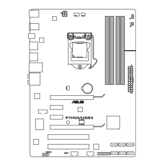
Motherboard overview 1.2.1 Motherboard layout Ensure that you install the motherboard into the chassis in the correct orientation. The edge with external ports goes to the rear part of the chassis. Place this side towards the rear of the chassis. Place six screws into the holes indicated by circles to secure the motherboard to the chassis. -
Page 15: Central Processing Unit (Cpu)
Contact your retailer immediately if the PnP cap is missing, or if you see any damage to the PnP cap/socket contacts/motherboard components. ASUS will shoulder the cost of repair only if the damage is shipment/transit-related. • Keep the cap after installing the motherboard. ASUS will process Return Merchandise Authorization (RMA) requests only if the motherboard comes with the cap on the LGA1156 socket. - Page 16 Lift the load lever in the direction of the arrow until the load plate is completely lifted. Load plate Remove the PnP cap from the CPU socket by lifting the tab only. PnP cap Cap tab Position the CPU over the socket, ensuring that the gold triangle is on the bottom-left corner of the socket, and then CPU notches...
- Page 17 Close the load plate (A), and then push down the load lever (B), ensuring that the front edge of the load plate slides under the retention knob (C). Insert the load lever under the retention tab. ASUS P7H55/USB3...
-
Page 18: Installing The Cpu Heatsink And Fan
1.3.2 Installing the CPU heatsink and fan The Intel LGA1156 processor requires a specially designed heatsink and fan assembly to ® ensure optimum thermal condition and performance. • When you buy a boxed Intel processor, the package includes the CPU fan and heatsink ®... -
Page 19: Uninstalling The Cpu Heatsink And Fan
Rotate each fastener counterclockwise. Pull up two fasteners at a time in a diagonal sequence to disengage the heatsink and fan assembly from the motherboard. Carefully remove the heatsink and fan assembly from the motherboard. ASUS P7H55/USB3... -
Page 20: System Memory
System memory 1.4.1 Overview The motherboard comes with four Double Data Rate 3 (DDR3) Dual Inline Memory Modules (DIMM) sockets. A DDR3 module has the same physical dimensions as a DDR2 DIMM but is notched differently to prevent installation on a DDR2 DIMM socket. DDR3 modules are developed for better performance with less power consumption. -
Page 21: Memory Configurations
• According to Intel spec definition, DDR3-1600 is supported for one DIMM per channel only. ASUS exclusively provides two DDR3-1600 DIMM support for each memory channel. • According to Intel CPU spec, DIMM voltage below 1.65V is recommended to protect the CPU. - Page 22 P7H55/USB3 Motherboard Qualified Vendors Lists (QVL) DDR3-2200MHz capability for Intel Lynnfield CPU DIMM socket support (Optional) Vendor Part No. Size SS/DS Chip Brand Chip NO. Timing Voltage F3-17600CL9D-4GBTDS G.SKILL 9-9-9-24 1.65 • (XMP) (2 x 2GB) P7H55/USB3 Motherboard Qualified Vendors Lists (QVL) DDR3-2133MHz capability for Intel Lynnfield CPU DIMM socket support (Optional)
- Page 23 • • • KINGSTON KHX1600C8D3T1K2/4GX(XMP) 4GB(2 x 2GB) 1.65 • • • KINGSTON KHX1600C9D3K3/6GX(XMP) 6GB(3 x 2GB) 1.65 • • • OCZ3G1600LV3GK 3GB(3 x 1GB) 8-8-8 1.65 • • OCZ3P1600LV3GK 3GB(3 x 1GB) 7-7-7 1.65 • • ASUS P7H55/USB3 1-11...
- Page 24 M378B2873EH1-CH9 SAMSUNG K4B1G0846E • • SAMSUNG M378B5673EH1-CH9 SAMSUNG K4B1G0846E • • • Asint SLZ3128M8-EDJE ELPIDA J1108BASE-DJ-E • • ASUS • • AQ28M72D8BJH9S SAMSUNG K4B1G0846D(ECC) • • • AQ56M72E8BJH9S SAMSUNG K4B1G0846D(ECC) • • • BUFFALO FSH1333D3G-T3G(XMP) 3GB(3 x 1GB) SS 7-7-7-20 - •...
- Page 25 6GB(3 x 2GB) DS 8-8-8 • • • AL7F8G73D-DG1 A3P1GF3DGF • • • AL8F8G73D-DG1 A3P1GF3DGF • • • SAMSUNG M378B2873DZ1-CH9 SAMSUNG K4B1G0846D • • • SAMSUNG M378B2873EH1-CH9 SAMSUNG K4B1G0846E • • • SAMSUNG M391B2873DZ1-CH9 SAMSUNG K4B1G0846D(ECC) 9 • • • ASUS P7H55/USB3 1-13...
- Page 26 P7H55/USB3 Motherboard Qualified Vendors Lists (QVL) DDR3-1333MHz capability for Intel Clarkdale CPU (continued) DIMM socket support Timing Vendor Part No. Size Chip Brand Chip NO. Voltage (Optional) Dimm(Bios) SAMSUNG M378B5673DZ1-CH9 SAMSUNG K4B1G0846D • • • SAMSUNG M378B5673EH1-CH9 SAMSUNG K4B1G0846E • •...
- Page 27 • Hyper DIMM support is subject to the physical characteristics of individual CPUs. • According to Intel spec definition, DDR3-1600 is supported for one DIMM per channel only. ASUS exclusively provides two DDR3-1600 DIMM support for each memory channel. • According to Intel CPU spec, CPUs with a core frequency of 2.66G support the maximum DIMM frequency of up to DDR3-1333.
-
Page 28: Installing A Dimm
1.4.3 Installing a DIMM Ensure to unplug the power supply before adding or removing DIMMs or other system components. Failure to do so may cause severe damage to both the motherboard and the components. DIMM notch Unlock a DIMM socket by pressing the retaining clips outward. -
Page 29: Expansion Slot
• We recommend that you provide sufficient power when running CrossFireX™ mode. • Connect a chassis fan to the motherboard connector labeled CHA_FAN when using multiple graphics cards for better thermal environment. ASUS P7H55/USB3 1-17... -
Page 30: Jumpers
Jumpers Clear RTC RAM (3-pin CLRTC) This jumper allows you to clear the Real Time Clock (RTC) RAM in CMOS. You can clear the CMOS memory of date, time, and system setup parameters by erasing the CMOS RTC RAM data. The onboard button cell battery powers the RAM data in CMOS, which include system setup information such as system passwords. -
Page 31: Onboard Switches
• If the installed DIMMs still fail to boot after the whole tuning process, the DRAM_LED lights continuously. Replace the DIMMs with ones recommended in the Memory QVL (Qualified Vendors Lists) in this user manual or on the ASUS website at www.asus.com. - Page 32 Turbo Key II switch This switch allows you to auto-tune your CPU to enhance the system performance. For ensuring the system performance, turn the switch setting to Enable when the system is powered off. • The LED near the Turbo Key II switch lights when the switch setting is turned to Enable. •...
-
Page 33: Connectors
Side Speaker Out port (gray). This port connects the side speakers in an 8-channel audio configuration. Microphone port (pink). This port connects a microphone. Refer to the audio configuration table on the next page for the function of the audio ports in 2, 4, 6, or 8-channel configuration. ASUS P7H55/USB3 1-21... -
Page 34: Internal Connectors
• Do not forget to connect the 4-pin EATX12V power plug. Otherwise, the system will not boot. • If you are uncertain about the minimum power supply requirement for your system, refer to the Recommended Power Supply Wattage Calculator at http://support.asus. com/PowerSupplyCalculator/PSCalculator.aspx?SLanguage=en-us for details. 1-22... - Page 35 This connector is for an additional Sony/Philips Digital Interface (S/PDIF) port(s). Connect the S/PDIF Out module cable to this connector, then install the module to a slot opening at the back of the system chassis. The S/PDIF module is purchased separately. ASUS P7H55/USB3 1-23...
- Page 36 Front panel audio connector (10-1 pin AAFP) This connector is for a chassis-mounted front panel audio I/O module that supports either HD Audio or legacy AC`97 audio standard. Connect one end of the front panel audio I/O module cable to this connector. •...
- Page 37 XP Service Pack 2 or later version before using Serial ATA ® hard disk drives. • When using hot-plug and NCQ, set the Configure SATA as item in the BIOS to [AHCI]. See section Storage Configuration for details. ASUS P7H55/USB3 1-25...
-
Page 38: System Panel Connector (20-8 Pin Panel)
System panel connector (20-8 pin PANEL) This connector supports several chassis-mounted functions. • System power LED (2-pin PLED) This 2-pin connector is for the system power LED. Connect the chassis power LED cable to this connector. The system power LED lights up when you turn on the system power, and blinks when the system is in sleep mode. - Page 39 Never connect a 1394 cable to the USB connectors. Doing so will damage the motherboard! You can connect the front panel USB cable to the ASUS Q-Connector (USB, blue) first, and then install the Q-Connector (USB) to the USB connector onboard if your chassis supports front panel USB ports.
-
Page 40: Installing An Operating System
The contents of the support DVD are subject to change at any time without notice. Visit the ASUS website at www.asus.com for updates. 1.10.1 Running the support DVD Place the support DVD into the optical drive. -
Page 41: Chapter 2: Bios Setup
BIOS in the future. Copy the original motherboard BIOS using the ASUS Update utility. 2.1.1 ASUS Update The ASUS Update is a utility that allows you to manage, save, and update the motherboard BIOS in Windows environment. ®... -
Page 42: Asus Ez Flash 2
Load Setup Defaults item under the Exit menu. See section Exit Menu for details. 2.1.2 ASUS EZ Flash 2 The ASUS EZ Flash 2 feature allows you to update the BIOS without using an OS-based utility. Before you start using this utility, download the latest BIOS file from the ASUS website at www.asus.com. -
Page 43: Asus Crashfree Bios 3 Utility
The BIOS file in the motherboard support DVD may be older than the BIOS file published on the ASUS official website. If you want to use the newer BIOS file, download the file at support.asus.com and save it to a USB flash drive. -
Page 44: Bios Setup Program
• The BIOS setup screens shown in this section are for reference purposes only, and may not exactly match what you see on your screen. • Visit the ASUS website at www.asus.com to download the latest BIOS file for this motherboard. -
Page 45: Sata 1-6
(Ultra DMA). Setting to [Auto] allows automatic selection of the DMA mode. SMART Monitoring [Auto] [Auto] Allows automatic selection of the S.M.A.R.T (Smart Monitoring, Analysis, and Reporting Technology). [Enabled] Enables the S.M.A.R.T feature. [Disabled] Disables the S.M.A.R.T feature. ASUS P7H55/USB3... -
Page 46: Storage Configuration
32Bit Data Transfer [Enabled] [Enabled] Sets the IDE controller to combine two 16-bit reads from the hard disk into a single 32-bit double word transfer to the processor. This makes more efficient use of the PCI bus as fewer transactions are needed for the transfer of a particular amount of data. -
Page 47: System Information
2.3.4 System Information This menu gives you an overview of the general system specifications. The BIOS automatically detects the BIOS information, CPU specification, and system memory in this menu. ASUS P7H55/USB3... -
Page 48: Ai Tweaker Menu
CPU level. Xtreme Phase Full Power Mode [Auto] DRAM Frequency [Auto] QPI Frenquency [Auto] Select Screen ←→ ASUS/3rd Party UI Priority [ASUS Utility] Select Item ↑↓ Change Option OC Tuner [Turbo Profile] General Help Start auto tuning Save and Exit... -
Page 49: Ai Overclock Tuner
D.O.C.P. D.O.C.P. • When using DIMMs with a frequncy higher than the Intel CPU spec, use this ASUS ® exclusive DRAM O.C. Profile function to overclock the DRAM. • Adjust BCLK frequency to obtain a better performance after applying the D.O.C.P function. -
Page 50: Intel(R) Speedstep(Tm) Tech
[ASUS Utility] Prioritizes the usage of ASUS utilities (ASUS EPU, TurboV EVO, etc.). Other 3rd party OC utilities may not be full-functioned. [3rd Party Utility] Prioritizes 3rd party OC utilities (IXTU, SetFS, etc.). ASUS utilities can’t be launched. 2-10 Chapter 2: BIOS information... -
Page 51: Oc Tuner
DRAM Clock] [160 DRAM Clock] [170 DRAM Clock] [180 DRAM Clock] [190 DRAM Clock] [200 DRAM Clock] WRITE Recovery Time [Auto] Configuration options: [Auto] [1 DRAM Clock] – [18 DRAM Clock] READ to PRE Time [Auto] Configuration options: [Auto] [1 DRAM Clock] – [15 DRAM Clock] ASUS P7H55/USB3 2-11... - Page 52 FOUR ACT WIN Time [Auto] Configuration options: [Auto] [1 DRAM Clock] – [63 DRAM Clock] Back-To-Back CAS# Delay [Auto] Configuration options: [Auto] [4 DRAM Clock] – [32 DRAM Clock] 2nd Information: 2N-44-0 The values vary depending on your settings of the following sub-items: Timing Mode [Auto] Configuration options: [Auto] [1N] [2N] [3N] Round Trip Latency on CHA/B [Auto]...
-
Page 53: Cpu Differential Amplitude
2.4.17 DRAM Voltage [Auto] Allows you to set the DRAM voltage. The values range from 1.2V to 2.0V with a 0.0125V interval. According to Intel CPU spec, DIMM voltage below 1.65V is recommended to protect the CPU. ASUS P7H55/USB3 2-13... -
Page 54: Cpu Pll Voltage
2.4.18 CPU PLL Voltage [Auto] Allows you to set the CPU PLL voltage. The values range from 1.8V to 2.5V with a 0.0125V interval. 2.4.19 PCH Voltage [Auto] Allows you to set the Platform Controller Hub voltage. The values range from 1.05V to 1.5V with a 0.0125V interval. -
Page 55: Advanced Menu
Adjacent Cache Line Prefetcher [Enabled] [Enabled] Enables the Adjacent Cache Line Prefetcher function. This item should be enabled in order to enable the L2 cache (MLC) Spatial Prefetcher for tuning performance of the specific application. [Disabled] Disables this function. ASUS P7H55/USB3 2-15... - Page 56 Max CPUID Value Limit [Disabled] [Enabled] Allows legacy operating systems to boot even without support for CPUs with extended CPUID functions. [Disabled] Disables this function. Intel(R) Virtualization Tech [Enabled] [Enabled] Allows a hardware platform to run multiple operating systems separately and simultaneously, enabling one system to virtually function as several systems.
-
Page 57: Uncore Configuration
The items in this menu allows you to change the USB-related features. Select an item then press <Enter> to display the configuration options. The USB Devices Enabled item shows the auto-detected values. If no USB device is detected, the item shows None. ASUS P7H55/USB3 2-17... -
Page 58: Pcipnp
USB Functions [Enabled] [Enabled] Enables the USB Host Controllers. [Disabled] Disables the controllers. The following items appear only when you set USB Support to [Enabled]. Legacy USB Support [Auto] [Disabled] Disables the function. [Enabled] Enables the support for USB devices on legacy operating systems (OS). [Auto] Allows the system to detect the presence of USB devices at startup. -
Page 59: Power Menu
Allows BIOS to switch off some power at S5 state to get system ready for the EuP requirement. When set to [Enabled], power for WOL, WO_USB, audio and onboard LEDs will be switched off at S5 state. ASUS P7H55/USB3 2-19... -
Page 60: Apm Configuration
2.6.6 APM Configuration Restore On AC Power Loss [Power Off] [Power Off] The system goes into off state after an AC power loss. [Power On] The system goes into on state after an AC power loss. [Last State] The system goes into either off or on state, whatever the system state was before the AC power loss. -
Page 61: Hardware Monitor
Configuration options: [20%] [30%] [40%] [50%] [60%] [70%] [80%] [90%] [100%] CPU Lower Temperature [40�C/104�F] Displays the lower limit of the CPU temperature. CPU Fan Min. Duty Cycle [20%] Chassis Q-Fan Control [Disabled] [Disabled] Disables the Chassis Q-Fan control feature. [Enabled] Enables the Chassis Q-Fan control feature. ASUS P7H55/USB3 2-21... -
Page 62: Boot Menu
Chassis Fan Profile [Standard] This item appears only when you enable the Chassis Q-Fan Control feature and allows you to set the appropriate performance level of the chassis fan. [Standard] Sets to [Standard] to make the chassis fan automatically adjust depending on the chassis temperature. -
Page 63: Security
Disables the full screen logo display feature. [Enabled] Enables the full screen logo display feature. Set this item to [Enabled] to use the ASUS MyLogo 2™ feature. AddOn ROM Display Mode [Force BIOS] [Force BIOS] The third-party ROM messages will be forced to display during the boot sequence. -
Page 64: Change User Password
After you have set a supervisor password, the other items appear to allow you to change other security settings. User Access Level [Full Access] This item allows you to select the access restriction to the Setup items. [No Access] Prevents user access to the Setup utility. [View Only] Allows access but does not allow change to any field. -
Page 65: Tools Menu
<Enter> to display the submenu. BIOS SETUP UTILITY Main Ai Tweaker Advanced Power Boot Tools Exit ASUS O.C. Profile AI NET 2 ASUS EZ Flash 2 Express Gate [Auto] Enter OS Timer [10 Seconds] Reset User Data [No] Select Screen ←→ Select Item ↑↓... -
Page 66: Asus Ez Flash 2
2.8.3 ASUS EZ Flash 2 Allows you to run ASUS EZ Flash 2. When you press <OK>, a confirmation message appears. Use the left/right arrow key to select between [Yes] or [No], then press <OK> to confirm your choice. 2.8.4 Express Gate [Auto] Allows you to enable or disable the ASUS Express Gate feature. -
Page 67: Exit Menu
When you select this option or if you press <F5>, a confirmation window appears. Select Ok to load default values. Select Exit & Save Changes or make other changes before saving the values to the non-volatile RAM. ASUS P7H55/USB3 2-27... - Page 68 2-28 Chapter 2: BIOS information...
-
Page 69: Asus Contact Information
+1-812-282-3777 +1-510-608-4555 Web site usa.asus.com Technical Support Telephone +1-812-282-2787 Support fax +1-812-284-0883 Online support support.asus.com ASUS COMPUTER GmbH (Germany and Austria) Address Harkort Str. 21-23, D-40880 Ratingen, Germany +49-2102-959911 Web site www.asus.de Online contact www.asus.de/sales Technical Support Telephone (Component) +49-1805-010923*...