Table of Contents
Advertisement
Advertisement
Table of Contents

Related Manuals for Asus P7P55D-E LX


Summary of Contents for Asus P7P55D-E LX
- Page 1 P7P55D-E LX...
- Page 2 Product warranty or service will not be extended if: (1) the product is repaired, modified or altered, unless such repair, modification of alteration is authorized in writing by ASUS; or (2) the serial number of the product is defaced or missing.
-
Page 3: Table Of Contents
Contents Contents ...................... iii Notices ......................vi Safety information ..................vii About this guide ..................viii P7P55D-E LX specifications summary ............. ix Chapter 1: Product introduction Welcome! ..................1-1 Package contents ................. 1-1 Special features ................1-1 1.3.1 Product highlights ............1-1 Before you proceed .............. -
Page 4: Contents
2.1.1 ASUS Update ..............2-1 2.1.2 ASUS EZ Flash 2 ............2-2 2.1.3 ASUS CrashFree BIOS 3 utility ........2-3 2.1.4 ASUS BIOS Updater ............2-4 BIOS setup program ..............2-7 Entering BIOS Setup at startup ............2-7 Entering BIOS Setup after POST ........... 2-7 Main menu .................. - Page 5 2.7.3 Security ................. 2-24 Tools menu ................. 2-25 2.8.1 ASUS O.C. Profile ............2-25 2.8.2 AI NET 2................ 2-26 2.8.3 ASUS EZ Flash 2 ............2-26 2.8.4 Express Gate ............... 2-26 2.8.5 IO Levelup ..............2-26 Exit menu ..................2-27...
-
Page 6: Notices
Complying with the REACH (Registration, Evaluation, Authorisation, and Restriction of Chemicals) regulatory framework, we published the chemical substances in our products at ASUS REACH website at http://green.asus.com/english/REACH.htm. DO NOT throw the motherboard in municipal waste. This product has been designed to enable proper reuse of parts and recycling. -
Page 7: Safety Information
Safety information Electrical safety • To prevent electrical shock hazard, disconnect the power cable from the electrical outlet before relocating the system. • When adding or removing devices to or from the system, ensure that the power cables for the devices are unplugged before the signal cables are connected. If possible, disconnect all power cables from the existing system before you add a device. -
Page 8: About This Guide
Refer to the following sources for additional information and for product and software updates. ASUS websites The ASUS website provides updated information on ASUS hardware and software products. Refer to the ASUS contact information. Optional documentation Your product package may include optional documentation, such as warranty flyers, that may have been added by your dealer. -
Page 9: P7P55D-E Lx Specifications Summary
CPUs. Some hyper DIMMs only support one DIMM per channel. Please refer to Memory QVL for details. ** Refer to www.asus.com or this user manual for the Memory QVL (Qualified Vendors Lists) Expansion Slots 1 x PCI Express 2.0 x 16 slot 4 x PCI Express 2.0 x1 slots (2.5GT/s) - Page 10 ASUS Q-LED (DRAM) ASUS Q-Slot ASUS Q-DIMM ASUS Unique Features ASUS IO Level UP for Ultra Performance - True USB 3.0 or True SATA 6Gb/s Support ASUS Xtreme Design ASUS Exclusive Overclocking Features - CPU Level UP, TurboV and Turbo Key...
- Page 11 1 x IO Level UP button BIOS Features 16 Mb Flash ROM, AMI BIOS, PnP, DMI 2.0, WfM 2.0, SM BIOS 2.5, ACPI 2.0a, Multi-language BIOS, ASUS EZ Flash 2, ASUS CrashFree BIOS 3 Manageability WfM 2.0, DMI 2.0, WOL by PME, WOR by PME, PXE...
-
Page 13: Chapter 1: Product Introduction
® The motherboard delivers a host of new features and latest technologies, making it another standout in the long line of ASUS quality motherboards! Before you start installing the motherboard, and hardware devices on it, check the items in your package with the list below. -
Page 14: Before You Proceed
True USB 3.0 Support Experience ultra-fast data transfers at 4.8Gbps with USB 3.0—the latest connectivity standard. Built to connect easily with next generation components and peripherals, USB 3.0 transfers data 10X faster and is also backward compatible with USB 2.0 components. True SATA 6Gb/s Support Supporting next-generation Serial ATA (SATA) storage interface, this motherboard delivers up to 6.0Gb/s data transfer rates. -
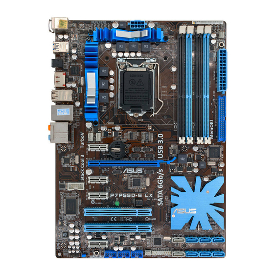
Page 15: Motherboard Layout
(40-1 pin PRI_IDE [Blue]) (4-1 pin SPDIF_OUT) Intel P55 Serial ATA connectors ® 1-23 Standby power LED 1-28 (7-pin SATA 1-6) Marvell Serial ATA 6.0 Gb/s connectors ® 1-26 Serial port connector (10-1 pin COM1) 1-25 (7-pin SATA_6G_1/2 [gray]) ASUS P7P55D-E LX... -
Page 16: Central Processing Unit (Cpu)
Contact your retailer immediately if the PnP cap is missing, or if you see any damage to the PnP cap/socket contacts/motherboard components. ASUS will shoulder the cost of repair only if the damage is shipment/transit-related. • Keep the cap after installing the motherboard. ASUS will process Return Merchandise Authorization (RMA) requests only if the motherboard comes with the cap on the LGA1156 socket. - Page 17 CPU notches. The CPU fits in only one correct orientation. DO NOT force the CPU into the socket to prevent bending Gold the connectors on the socket and triangle damaging the CPU! mark Alignment keys ASUS P7P55D-E LX...
- Page 18 Apply some Thermal Interface Material to the exposed area of the CPU that the heatsink will be in contact with, ensuring that it is spread in an even thin layer. Some heatsinks come with pre-applied thermal paste. If so, skip this step.
-
Page 19: Installing The Cpu Heatsink And Fan
Push down two fasteners at a time in a diagonal sequence to secure the heatsink and fan assembly in place. Orient the heatsink and fan assembly such that the CPU fan cable is closest to the CPU fan connector. ASUS P7P55D-E LX... -
Page 20: Uninstalling The Cpu Heatsink And Fan
Connect the CPU fan cable to the connector on the motherboard labeled CPU_FAN. DO NOT forget to connect the CPU fan connector! Hardware monitoring errors can occur if you fail to plug this connector. 1.6.3 Uninstalling the CPU heatsink and fan To uninstall the CPU heatsink and fan: Disconnect the CPU fan cable from the connector on the motherboard. -
Page 21: System Memory
The figure illustrates the location of the DDR3 DIMM sockets: Recommended memory configurations One DIMM: Install only one memory module in slot A1 or B1 as a single-channel operation. Two DIMMs (dual-channel operation): Four DIMMs (dual-channel operation): ASUS P7P55D-E LX... -
Page 22: Memory Configurations
1.7.2 Memory configurations You may install 1GB, 2GB and 4GB unbuffered and non-ECC DDR3 DIMMs into the DIMM sockets. • You may install varying memory sizes in Channel A and Channel B. The system maps the total size of the lower-sized channel for the dual-channel configuration. Any excess memory from the higher-sized channel is then mapped for single-channel operation. - Page 23 P7P55D-E LX Motherboard Qualified Vendors Lists (QVL) DDR3-1067MHz capability for CPU at 2.66, 2.8 and 2.93GHz DIMM socket Chip Timing support (Optional) Vendor Part No. Size Chip NO. Voltage Brand Lable(Bios) CORSAIR CM3X1024-1066C7 1024MB DS Heat-Sink Package • • •...
- Page 24 P7P55D-E LX Motherboard Qualified Vendors Lists (QVL) DDR3-1333MHz capability for CPU at 2.66, 2.8 and 2.93GHz (continued) DIMM socket support Timing Vendor Part No. Size DS Chip Brand Chip NO. Voltage (Optional) Dimm(Bios) Crucial CT25672BA1339.18FF 2048MB DS MICRON D9KPT(ECC) 9(1333-9-9-9-24) •...
- Page 25 P7P55D-E LX Motherboard Qualified Vendors Lists (QVL) DDR3-1600MHz capability for CPU at 2.66GHz DIMM socket support Chip Timing Vendor Part No. Size Chip NO. Voltage (Optional) Brand Dimm(Bios) A-DATA AD31600E001GMU 3072MB(Kit of 3) SS N/A Heat-Sink Package 8-8-8-24(1333-9-9-9-24) 1.65-1.85 •...
- Page 26 P7P55D-E LX Motherboard Qualified Vendors Lists (QVL) DDR3-1625MHz capability for CPU at 2.8 and 2.93GHz DIMM socket support SS/DS Chip Timing Vendor Part No. Size Chip NO. Lable(Bios) Voltage (Optional) Brand KINGSTON KHX13000D3LLK2/2GN(EPP) 2048MB(Kit of 2) Heat-Sink Package • •...
- Page 27 P7P55D-E LX Motherboard Qualified Vendors Lists (QVL) DDR3-1866MHz capability for CPU at 2.66GHz DIMM socket support Chip Timing Vendor Part No. Size Brand Chip NO. Voltage (Optional) Dimm(Bios) Apacer 78.0AGCQ.CBZ(XMP) 3GB(Kit of 3) Heat-Sink Package 9-9-9-27(1066-8-8-8-20) • Crucial BL12864BE2009.8SFB3(EPP) Heat-Sink Package 9-9-9-28(1333-9-9-9-24) •...
- Page 28 Hyper DIMM support is subject to the physical characteristics of individual CPUs. • According to Intel spec definition, DDR3-1600 is supported for one DIMM per channel only. ASUS exclusively provides two DDR3-1600 DIMM support for each memory channel. • According to Intel CPU spec, CPUs with a core frequency of 2.66G support the maximum DIMM frequency of up to DDR3-1333.
-
Page 29: Expansion Slot
This motherboard has one PCI Express 2.0 x16 slot that supports PCI Express x16 2.0 graphic cards complying with the PCI Express specifications. Refer to section 1-6 Motherboard overview for the location of the expansion slot. ASUS P7P55D-E LX 1-17... -
Page 30: Jumper
Jumper Clear RTC RAM (3-pin CLRTC) This jumper allows you to clear the Real Time Clock (RTC) RAM in CMOS. You can clear the CMOS memory of date, time, and system setup parameters by erasing the CMOS RTC RAM data. The onboard button cell battery powers the RAM data in CMOS, which include system setup information such as system passwords. -
Page 31: Onboard Switches
If the installed DIMMs still fail to boot after the whole tuning process, the DRAM_LED lights continuously. Replace the DIMMs with ones recommended in the Memory QVL (Qualified Vendors Lists) in this user manual or on the ASUS website at www.asus.com. - Page 32 IO Level UP The IO Level UP switch allows performance boost of the USB 3.0 ports on the rear panel or the onboard SATA 6Gb/s ports. Two LEDs with different colors are provided to indicate different speed mode. Press the IO Level UP switch and restart the system to light up the green (USB3.0) LED.
-
Page 33: Connectors
Front Speaker Out Front Speaker Out Pink Mic In Mic In Mic In Mic In Orange – – Center/Subwoofer Center/Subwoofer Black – Rear Speaker Out Rear Speaker Out Rear Speaker Out Gray – – – Side Speaker Out ASUS P7P55D-E LX 1-21... -
Page 34: Internal Connectors
• Do not forget to connect the 8-pin EATX12V power plug. Otherwise, the system will not boot. • If you are uncertain about the minimum power supply requirement for your system, refer to the Recommended Power Supply Wattage Calculator at http://support.asus. com/PowerSupplyCalculator/PSCalculator.aspx?SLanguage=en-us for details. CPU, chassis, and power fan connectors... -
Page 35: Serial Ata Connectors
If you installed Serial ATA hard disk drives, you can create a RAID 0, 1, 5, and 10 configuration with the Intel Matrix Storage Technology through the onboard Intel ® ® chipset. ASUS P7P55D-E LX 1-23... -
Page 36: System Panel Connector
• These connectors are set to Standard IDE mode by default. In Standard IDE mode, you can connect Serial ATA boot/data hard disk drives to these connectors. If you intend to create a Serial ATA RAID set using these connectors, set the Configure SATA as item in the BIOS to [RAID]. - Page 37 This connector is for a serial (COM) port. Connect the serial port module cable to this connector, then install the module to a slot opening at the back of the system chassis. The COM module is purchased separately. ASUS P7P55D-E LX 1-25...
- Page 38 Digital audio connector (4-1 pin SPDIF_OUT) This connector is for an additional Sony/Philips Digital Interface (S/PDIF) port(s). Connect the S/PDIF Out module cable to this connector, then install the module to a slot opening at the back of the system chassis. The S/PDIF module is purchased separately.
- Page 39 This prevents incorrect insertion when you connect the IDE cable. • Use the 80-conductor IDE cable for Ultra DMA 133/100/66 IDE devices. If any device jumper is set as “Cable-Select”, ensure that all other device jumpers have the same setting. ASUS P7P55D-E LX 1-27...
-
Page 40: Onboard Leds
1.11.3 Onboard LEDs POST State LED POST State LED checks DRAM during motherboard booting process. If an error is found , the LED next to the error device will continue lighting until the problem is solved. This user-friendly design provides an intuitive way to locate the root problem within seconds. -
Page 41: Installing An Operating System
The contents of the support DVD are subject to change at any time without notice. Visit the ASUS website at www.asus.com for updates. 1.13.1 Running the support DVD Place the support DVD into the optical drive. - Page 42 1-30 Chapter 1: Product introduction...
-
Page 43: Chapter 2: Bios Setup
BIOS in the future. Copy the original motherboard BIOS using the ASUS Update utility. 2.1.1 ASUS Update The ASUS Update is a utility that allows you to manage, save, and update the motherboard BIOS in Windows environment. ®... -
Page 44: Asus Ez Flash 2
Load Setup Defaults item under the Exit menu. See section 2.9 Exit Menu for details. 2.1.2 ASUS EZ Flash 2 The ASUS EZ Flash 2 feature allows you to update the BIOS without using an OS-based utility. Before you start using this utility, download the latest BIOS file from the ASUS website at www.asus.com. -
Page 45: Asus Crashfree Bios 3 Utility
The BIOS file in the motherboard support DVD may be older than the BIOS file published on the ASUS official website. If you want to use the newer BIOS file, download the file at support.asus.com and save it to a USB flash drive. -
Page 46: Asus Bios Updater
Insert the USB flash drive with the latest BIOS file and BIOS Updater to the USB port. Boot your computer. When the ASUS Logo appears, press <F8> to show the BIOS Boot Device Select Menu. Insert the support DVD into the optical drive and select the optical drive as the boot device. -
Page 47: Backing Up The Current Bios
ASUSTek BIOS Updater for DOS V1.00b [09/06/22] FLASH TYPE: MXIC 25L1605A Current ROM Update ROM BOARD: P7P55D-E LX BOARD: Unknown VER: 0019 VER: Unknown DATE: 12/02/2009 DATE: Unknown PATH: BIOS backup is done! Press any key to continue. Note Saving BIOS: ASUS P7P55D-E LX... -
Page 48: Updating The Bios File
D:\>bupdater /pc /g The BIOS Updater screen appears as below. ASUSTek BIOS Updater for DOS V1.00b [09/06/22] FLASH TYPE: MXIC 25L1605A Current ROM Update ROM BOARD: Unknown BOARD: P7P55D-E LX VER: Unknown VER: 0019 DATE: Unknown DATE: 12/02/2009 PATH: P7P55D.ROM... -
Page 49: Bios Setup Program
• The BIOS setup screens shown in this section are for reference purposes only, and may not exactly match what you see on your screen. • Visit the ASUS website at www.asus.com to download the latest BIOS file for this motherboard. -
Page 50: Sata 1-6
2.3.1 SATA 1-6 While entering Setup, the BIOS automatically detects the presence of IDE/SATA devices. There is a separate submenu for each IDE/SATA device. Select a device item then press <Enter> to display the SATA device information. The BIOS automatically detects the values opposite the dimmed items (Device, Vendor, Size, LBA Mode, Block Mode, PIO Mode, Async DMA, Ultra DMA, and SMART monitoring). -
Page 51: Ahci Configuration
Allows you to set the Self-Monitoring, Analysis and Reporting Technology. Configuration options: [Disabled] [Enabled] 2.3.4 System Information This menu gives you an overview of the general system specifications. The BIOS automatically detects the BIOS information, CPU specification, and system memory in this menu. ASUS P7P55D-E LX... -
Page 52: Ai Tweaker Menu
Ai Tweaker menu The Ai Tweaker menu items allow you to configure overclocking-related items. Be cautious when changing the settings of the Ai Tweaker menu items. Incorrect field values can cause the system to malfunction. The configuration options for this chapter vary depending on the CPU and DIMM model you installed on the motherboard. -
Page 53: Ai Overclock Tuner
D.O.C.P. D.O.C.P. • When using DIMMs with a frequncy higher than the Intel CPU spec, use this ASUS ® exclusive DRAM O.C. Profile function to overclock the DRAM. • Adjust BCLK frequency to obtain a better performance after applying the D.O.C.P function. -
Page 54: Cpu Ratio Setting
2.4.3 CPU Ratio Setting [Auto] Allows you to adjust the ratio between CPU Core Clock and BCLK Frequency. Use the <+> and <-> keys to adjust the value. The valid value ranges differently according to your CPU model. 2.4.4 Intel(R) SpeedStep(TM) Tech [Enabled] When set to [Disabled], the CPU runs at its default speed. -
Page 55: Dram Timing Control
Configuration options: [Auto] [4 DRAM Clock] [6 DRAM Clock] DRAM WRITE To WRITE Delay (DR) [Auto] Configuration options: [Auto] [2 DRAM Clock] – [9 DRAM Clock] DRAM WRITE To WRITE Delay (SR) [Auto] Configuration options: [Auto] [4 DRAM Clock] [6 DRAM Clock] ASUS P7P55D-E LX 2-13... -
Page 56: Cpu Differential Amplitude
2.4.10 CPU Differential Amplitude [Auto] Different AMP might enhance BCLK overclocking ability. Configuration options: [Auto] [700mV] [800mV] [900mV] [1000mV] 2.4.11 CPU Clock Skew [Auto] Adjusting this item may help enhancing BCLK overclocking ability. You may need to adjust the CPU Clock Skew item at the same time. Configuration options: [Auto] [Normal] [Delay 100ps]–[Delay 1500ps] Some of the following items are adjusted by typing the desired values using the numeric keypad and press the <Enter>... -
Page 57: Pch Voltage
Automatic configuration. [Disabled] Enhances the BCLK overclocking ability. [Enabled] Sets to [Enabled] for EMI control. 2.4.19 PCIE Spread Spectrum [Auto] [Auto] Automatic configuration. [Disabled] Enhances the PCIE overclocking ability. [Enabled] Sets to [Enabled] for EMI control. ASUS P7P55D-E LX 2-15... -
Page 58: Advanced Menu
Advanced menu The Advanced menu items allow you to change the settings for the CPU and other system devices. Be cautious when changing the settings of the Advanced menu items. Incorrect field values can cause the system to malfunction. BIOS SETUP UTILITY Main Ai Tweaker Advanced... - Page 59 This item appears only when you set the Intel(R) C-STATE Tech item to [Enabled]. We recommend that you set this item to [Auto] for BIOS to automatically detect the C-State mode supported by your CPU. Configuration options: [Auto] [C1] [C3] [C6] ASUS P7P55D-E LX 2-17...
-
Page 60: Uncore Configuration
2.5.2 Uncore Configuration The Uncore Configuration menu allows you to change the advanced chipset settings. Memory Remap Feature [Enabled] [Disabled] Do not allow remapping of memory. [Enabled] Allows for the segment of system memory that was previously overwritten by PCI devices to be remapped above the total physical memory. -
Page 61: Usb Configuration
[No] When set to [No], BIOS configures all the devices in the system. 2.5.6 Intel VT-d Configuration [Disabled] [Disabled] Disables the Intel Virtualization Technology for Directed I/O. [Enabled] Enables the Intel Virtualization Technology for Directed I/O. ASUS P7P55D-E LX 2-19... -
Page 62: Power Menu
Power menu The Power menu items allow you to change the settings for the Advanced Power Management (APM). Select an item then press <Enter> to display the configuration options. BIOS SETUP UTILITY Main Ai Tweaker Advanced Power Boot Tools Exit Select the ACPI state Suspend Mode [Auto]... -
Page 63: Apm Configuration
Power On By PS/2 Mouse [Disabled] [Disabled] Disables the Power On by a PS/2 mouse. [Enabled] Enables the Power On by a PS/2 mouse. This feature requires an ATX power supply that provides at least 1A on the +5VSB lead. ASUS P7P55D-E LX 2-21... -
Page 64: Hardware Monitor
2.6.7 Hardware Monitor CPU/MB Temperature [xxx�C/xxx�F] [xxx�C/xxx�F] The onboard hardware monitor automatically detects and displays the CPU and motherboard temperatures. Select Ignored if you do not wish to display the detected temperatures. CPU Fan Speed [xxxxRPM] or [Ignored] / [N/A] Chassis Fan 1/2 Speed [xxxxRPM] or [Ignored] / [N/A] Power Fan Speed [xxxxRPM] or [Ignored] / [N/A] The onboard hardware monitor automatically detects and displays the CPU, chassis,... -
Page 65: Boot Menu
Disables the full screen logo display feature. [Enabled] Enables the full screen logo display feature. Set this item to [Enabled] to use the ASUS MyLogo 2™ feature. AddOn ROM Display Mode [Force BIOS] [Force BIOS] The third-party ROM messages will be forced to display during the boot sequence. -
Page 66: Security
2.7.3 Security The Security menu items allow you to change the system security settings. Select an item then press <Enter> to display the configuration options. Change Supervisor Password Select this item to set or change the supervisor password. The Supervisor Password item on top of the screen shows the default Not Installed. -
Page 67: Tools Menu
<Enter> to display the submenu. BIOS SETUP UTILITY Main Ai Tweaker Advanced Power Boot Tools Exit ASUS O.C. Profile AI NET 2 ASUS EZ Flash 2 Express Gate [Auto] Enter OS Timer [10 Seconds] Reset User Data [No] IO Levelup [Disabled] Select Screen ←→... -
Page 68: Ai Net 2
(POST). 2.8.3 ASUS EZ Flash 2 Allows you to run ASUS EZ Flash 2. When you press <Enter>, a confirmation message appears. Use the left/right arrow key to select between [Yes] or [No], then press <Enter> to confirm your choice. -
Page 69: Exit Menu
When you select this option or if you press <F5>, a confirmation window appears. Select Ok to load default values. Select Exit & Save Changes or make other changes before saving the values to the non-volatile RAM. ASUS P7P55D-E LX 2-27... - Page 70 2-28 Chapter 2: BIOS information...