Table of Contents
Advertisement
Advertisement
Table of Contents

Related Manuals for Asus P7H55-M SI


Summary of Contents for Asus P7H55-M SI
- Page 1 P7H55-M SI...
- Page 2 Product warranty or service will not be extended if: (1) the product is repaired, modified or altered, unless such repair, modification of alteration is authorized in writing by ASUS; or (2) the serial number of the product is defaced or missing.
-
Page 3: Table Of Contents
Contents Notices ......................v Safety information ..................vi About this guide ..................vi P7H55-M SI specifications summary ............viii Chapter 1: Product introduction Before you proceed ..............1-1 Motherboard overview ..............1-2 1.2.1 Motherboard layout ............1-2 1.2.2 Layout contents ............... 1-2 Central Processing Unit (CPU) ........... - Page 4 APM Configuration ............2-16 2.5.6 Hardware Monitor ............2-17 Boot menu .................. 2-18 2.6.1 Boot Device Priority ............2-18 2.6.2 Boot Settings Configuration .......... 2-18 2.6.3 Security ................. 2-19 Tools menu ................. 2-20 ASUS EZ Flash 2 ................. 2-20 Exit menu ..................2-21...
-
Page 5: Notices
Complying with the REACH (Registration, Evaluation, Authorisation, and Restriction of Chemicals) regulatory framework, we published the chemical substances in our products at ASUS REACH website at http://green.asus.com/english/REACH.htm DO NOT throw the motherboard in municipal waste. This product has been designed to enable proper reuse of parts and recycling. -
Page 6: Safety Information
Safety information Electrical safety • To prevent electric shock hazard, disconnect the power cable from the electric outlet before relocating the system. • When adding or removing devices to or from the system, ensure that the power cables for the devices are unplugged before the signal cables are connected. If possible, disconnect all power cables from the existing system before you add a device. -
Page 7: Conventions Used In This Guide
Refer to the following sources for additional information and for product and software updates. ASUS websites The ASUS website provides updated information on ASUS hardware and software products. Optional documentation Your product package may include optional documentation, such as warranty flyers, that may have been added by your dealer. -
Page 8: P7H55-M Si Specifications Summary
3GB. We recommend a maximum of 3GB system memory if you are using a Windows 32-bit OS. ® ** Refer to www.asus.com for the latest Memory QVL (Qualified Vendors List). Expansion Slots 1 x PCIe 2.0 x16 slot 1 x PCIe 2.0 x1 slot... - Page 9 P7H55-M SI specifications summary Back Panel I/O Ports 1 x PS/2 Keyboard port 1 x PS/2 Mouse port 1 x HDMI port 1 x DVI port 1 x VGA port 1 x COM port 1 x RJ45 port 6 x USB 2.0/1.1 ports...
-
Page 11: Chapter 1: Product Introduction
Chapter 1 Product introduction Thank you for buying an ASUS P7H55-M SI motherboard! ® Before you start installing the motherboard, and hardware devices on it, check the items in your motherboard package. Refer to page ix for the list of accessories. -
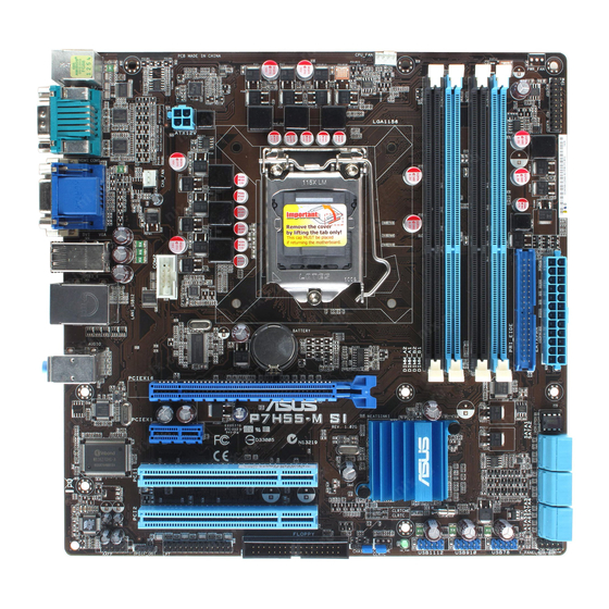
Page 12: Motherboard Overview
CPU_FAN HDMI ATX12V Place this side towards CHA_FAN the rear of the chassis. LGA1156 COM2 USB3_6 LAN1_USB12 Lithium Cell CMOS Power AUDIO PCIEX16 8112L P7H55-M SI BIOS PCIEX1_1 Intel ® Super GMA4500 PCI1 PCI2 VT1708S USB910 USB78 FLOPPY USB1112 AAFP... -
Page 13: Central Processing Unit (Cpu)
Contact your retailer immediately if the PnP cap is missing, or if you see any damage to the PnP cap/socket contacts/motherboard components. ASUS will shoulder the cost of repair only if the damage is shipment/transit-related. • Keep the cap after installing the motherboard. ASUS will process Return Merchandise Authorization (RMA) requests only if the motherboard comes with the cap on the LGA1156 socket. -
Page 14: Memory Configurations
OS if you want to install 4GB or more memory on the ® motherboard. • This motherboard does not support DIMMs made up of 256 megabits (Mb) chips or less. P7H55-M SI Motherboard Qualified Vendors List (QVL) DDR3-1333MHz capability DIMM Timing... - Page 15 DS - Heat-Sink Package 7-7-7-20 • • • Elixir M2Y2G64CB8HC9N-CG 2048MB DS Elixir Heat-Sink Package • • • Kingtiger 2GB DIMM PC3-10666 2048MB DS SAMSUNG SEC 904 HCH9 • • • K4B1G0846D (continued on the next page) ASUS P7H55-M SI...
- Page 16 Dual-channel memory configuration. • C*: Supports two pairs of modules inserted into both the blue and black slots as two pairs of Dual-channel memory configuration. Visit the ASUS website at www.asus.com for the latest QVL. Chapter 1: Product introduction...
-
Page 17: Expansion Slots
This motherboard supports PCI Express x1 network cards, SCSI cards and other cards that comply with the PCI Express specifications. 1.5.5 PCI Express x16 slot This motherboard supports PCI Express x16 graphics cards that comply with the PCI Express specifications. ASUS P7H55-M SI... -
Page 18: Jumpers
Normal Clear RTC (Default) P7H55-M SI Clear RTC RAM To erase the RTC RAM: Turn OFF the computer and unplug the power cord. Move the jumper cap from pins 1-2 (default) to pins 2-3. Keep the cap on pins 2-3 for about 5-10 seconds, then move the cap back to pins 1-2. -
Page 19: Connectors
Rear Speaker Out Rear Speaker Out Rear Speaker Out Lime (Rear panel) Line Out Front Speaker Out Front Speaker Out Front Speaker Out Pink (Rear panel) Mic In Mic In Bass/Center Bass/Center Lime (Front panel) Side Speaker Out ASUS P7H55-M SI... -
Page 20: Internal Connectors
USB78 PIN 1 PIN 1 PIN 1 P7H55-M SI P7H55-M SI USB2.0 connectors Never connect a 1394 cable to the USB connectors. Doing so will damage the motherboard! The USB 2.0 module is purchased separately. 1-10 Chapter 1: Product introduction... - Page 21 XP Service Pack 2 or later version before using Serial ATA. ® Digital audio connector (4-1 pin SPDIF_OUT) This connector is for an additional Sony/Philips Digital Interface (S/PDIF) port. P7H55-M SI SPDIF_OUT P7H55-M SI Digital audio connector The S/PDIF module is purchased separately. ASUS P7H55-M SI 1-11...
- Page 22 By default , the pin labeled “Chassis Signal” and “ Ground” are shorted with a jumper cap. Remove the jumper caps only when you intend to use the chassis intrusion detection feature. P7H55-M SI CHASSIS P7H55-M SI Chassis intrusion connector 1-12 Chapter 1: Product introduction...
-
Page 23: Atx Power Connectors
The system may become unstable or may not boot up if the power is inadequate. • If you are uncertain about the minimum power supply requirement for your system, refer to the Recommended Power Supply Wattage Calculator at http://support.asus. com/PowerSupplyCalculator/PSCalculator.aspx?SLanguage=en-us for details. ASUS P7H55-M SI... -
Page 24: System Panel Connector
PIN 1 P7H55-M SI HD_LED RESET P7H55-M SI System panel connector • System power LED (2-pin PLED) This 2-pin connector is for the system power LED. Connect the chassis power LED cable to this connector. The system power LED lights up when you turn on the system power, and blinks when the system is in sleep mode. - Page 25 P7H55-M SI Analog front panel connector If you want to connect a high-definition front panel audio module to this connector, ensure that the Front Panel Type item in the BIOS is set to [HD Audio]. If you want to connect an AC97 front panel audio module to this connector, set the item to [AC97].
- Page 26 The serial port bracket (COM2) is purchased separately. COM2 PIN 1 P7H55-M SI P7H55-M SI Serial port (COM2) connector 1-16 Chapter 1: Product introduction...
- Page 27 If any device jumper is set as “Cable-Select”, ensure that all other device jumpers have the same setting. PRI_IDE P7H55-M SI NOTE:Orient the red markings on the IDE ribbon cable to PIN 1. P7H55-M SI IDE connector ASUS P7H55-M SI 1-17...
-
Page 28: Software Support
Place the Support DVD into the optical drive. The DVD automatically displays the Drivers menu if the Autorun function is enabled on your computer. The contents of the Support DVD are subject to change at any time without notice. Visit the ASUS website at www.asus.com for updates. Click an icon to display Support... -
Page 29: Chapter 2: Bios Information
BIOS in the future. Copy the original motherboard BIOS using the ASUS Update utility. 2.1.1 ASUS Update utility The ASUS Update is a utility that allows you to manage, save, and update the motherboard BIOS in Windows environment. ®... -
Page 30: Asus Ez Flash 2 Utility
Follow the onscreen instructions to complete the updating process. 2.1.2 ASUS EZ Flash 2 utility The ASUS EZ Flash 2 feature allows you to update the BIOS without using an OS-based utility. To update the BIOS using EZ Flash 2:... -
Page 31: Asus Bios Updater
When the correct BIOS file is found, EZ Flash 2 performs the BIOS update process and automatically reboots the system when done. • Only a USB flash disk with FAT 32/16 format and single partition can support the ASUS EZ Flash 2 utility. - Page 32 The BIOS Updater backup screen appears indicating the BIOS backup process. When BIOS backup is done, press any key to return to the DOS prompt. ASUSTek BIOS Updater for DOS V1.00b [09/06/22] FLASH TYPE:Winbond 25X/Q64 Current ROM Update ROM BOARD: P7H55-M SI BOARD: Unknown VER: 0207 VER: Unknown DATE:...
-
Page 33: Updating The Bios File
Select the Load Setup Defaults item under the Exit BIOS menu. See section 2.8 Exit menu for details. • Ensure to connect all SATA hard disk drives after updating the BIOS file if you have disconnected them. ASUS P7H55-M SI... -
Page 34: Asus Crashfree Bios
2.1.4 ASUS CrashFree BIOS The ASUS CrashFree BIOS is an auto recovery tool that allows you to restore the BIOS file when it fails or gets corrupted during the updating process. You can restore a corrupted BIOS file using the motherboard support DVD or a removable device that contains the updated BIOS file. -
Page 35: Bios Setup Program
• The BIOS setup screens shown in this section are for reference purposes only, and may not exactly match what you see on your screen. • Visit the ASUS website at www.asus.com to download the latest BIOS file for this motherboard. -
Page 36: Main Menu
Main menu When you enter the BIOS Setup program, the Main menu screen appears, giving you an overview of the basic system information. BIOS SETUP UTILITY Main Advanced Power Boot Tools Exit Use [ENTER], [TAB] or System Time [00:31:48] [SHIFT-TAB] to select System Date [Fri 04/10/2009] a field. -
Page 37: Storage Configuration
Disables or enables device write protection. This will be effective only if device is accessed through BIOS. Configuration option: [Disabled] [Enabled] IDE Detect Time Out (Sec) [35] Selects the time out value for detecting ATA/ATAPI devices. Configuration options: [0] [5] [10] [15] [20] [25] [30] [35] ASUS P7H55-M SI... -
Page 38: System Information
2.3.7 System Information This menu gives you an overview of the general system specifications. The BIOS automatically detects the items in this menu. Bios Information Displays the auto-detected BIOS information. Processor Displays the auto-detected CPU specification. System Memory Displays the auto-detected system memory. Advanced menu The Advanced menu items allow you to change the settings for the CPU and other system devices. - Page 39 Intel(R) SpeedStep(TM) Tech [Enabled] When this item is set to [Enabled], the CPU speed is controlled by the operating system. When this item is set to [Disabled], the CPU runs at its default speed. Configuration options: [Enabled] [Disabled] ASUS P7H55-M SI 2-11...
-
Page 40: Chipset
Intel(R) TurboMode Tech [Enabled] This item appears only if you set the CPU Ratio Setting item to [Auto]. Turbo mode allows processor cores to run faster than marked frequency in specific condition. Configuration options: [Disabled] [Enabled] Intel(R) C-STATE Tech [Enabled] Allows you enable or disable the Intel C-STATE Technology. - Page 41 Appears only when the Parallel Port Mode item is set to [EPP]. This item allows you to select the EPP version. Configuration options: [1.9] [1.7] Parallel Port IRQ [IRQ7] Allows you to select parallel port IRQ. Configuration options: [IRQ5] [IRQ7] ASUS P7H55-M SI 2-13...
-
Page 42: Usb Configuration
2.4.4 USB Configuration The items in this menu allows you to change the USB-related features. Select an item then press <Enter> to display the configuration options. The Module Version and USB Devices Enabled items show the auto-detected values. If no USB device is detected, the item shows None. -
Page 43: Tpm Configuration
After you select [OK] to execute the Clearing the TPM function, the data saved in the TPM security chip will be cleared and can never be restored. 2.4.7 Intel VT-d Configuration Intel VT-d [Disabled] Allows you to enable or disable the Intel Virtualization Technology for Directed I/O. ® Configuration options: [Disabled] [Enabled] ASUS P7H55-M SI 2-15... -
Page 44: Power Menu
Power menu The Power menu items allow you to change the settings for the Advanced Power Management (APM). Select an item then press <Enter> to display the configuration options. BIOS SETUP UTILITY Main Advanced Power Boot Tools Exit Select the ACPI state Suspend Mode [Auto] used for System... -
Page 45: Hardware Monitor
The onboard hardware monitor automatically detects and displays the Chassis fan speed in rotations per minute (RPM). If the fan is not connected to the motherboard, the field shows N/A. Select Ignored if you do not wish to display the detected speed. ASUS P7H55-M SI 2-17... -
Page 46: Boot Menu
Configuration options: [Removable Dev.] [Hard Drive] [ATAPI CD-ROM] [Disabled] • To select the boot device suring system startup, press <F8> when ASUS Logo appears. • To access Windows OS in Safe Mode, do any of the following: ®... -
Page 47: Security
After you have set a supervisor password, the other items appear to allow you to change other security settings. User Access Level [Full Access] This item allows you to select the access restriction to the Setup items. Configuration options: [No Access] [View Only] [Limited] [Full Access] ASUS P7H55-M SI 2-19... -
Page 48: Tools Menu
3. CD-DISC (read only) ASUS EZ Flash 2 Allows you to run ASUS EZ Flash 2. When you press <Enter>, a confirmation message appears. Use the left/right arrow key to select between [Yes] or [No], then press <Enter> to confirm your choice. Please see section 2.1.2 for details. -
Page 49: Exit Menu
When you select this option or if you press <F5>, a confirmation window appears. Select OK to load default values. Select Exit & Save Changes or make other changes before saving the values to the non-volatile RAM. ASUS P7H55-M SI 2-21... - Page 50 2-22 Chapter 2: BIOS information...