Table of Contents
Advertisement
Advertisement
Table of Contents

Related Manuals for Asus P7H55-M


Summary of Contents for Asus P7H55-M
- Page 1 P7H55-M/USB3...
- Page 2 Product warranty or service will not be extended if: (1) the product is repaired, modified or altered, unless such repair, modification of alteration is authorized in writing by ASUS; or (2) the serial number of the product is defaced or missing.
-
Page 3: Table Of Contents
Contents Notices ......................vii Safety information ..................viii About this guide ..................viii P7H55-M/USB3 specifications summary ........... x Chapter 1: Product introduction Welcome! ..................1-1 Package contents ................. 1-1 Special features ................1-1 1.3.1 Product highlights ............1-1 1.3.2 Innovative ASUS features ..........1-3 Before you proceed .............. - Page 4 Chapter 2: BIOS information Managing and updating your BIOS ..........2-1 2.1.1 ASUS Update utility ............2-1 2.1.2 ASUS EZ Flash 2 ............2-2 2.1.3 ASUS CrashFree BIOS ........... 2-3 2.1.4 ASUS BIOS Updater ............2-3 BIOS setup program ..............2-6 2.2.1...
- Page 5 Contents 2.4.7 DRAM Frequency [Auto] ..........2-14 2.4.8 QPI Frequency [Auto] ........... 2-14 2.4.9 OC Tuner Utility ............. 2-14 2.4.10 OC Tuner Limit Value ............ 2-14 2.4.11 DRAM Timing Control [Auto] ......... 2-14 2.4.12 CPU Differential Amplitude [Auto] ......... 2-16 2.4.13 CPU Clock Skew [Auto] ..........
- Page 6 Tools menu ................. 2-28 2.8.1 ASUS O.C. Profile ............2-28 2.8.2 AI NET 2................ 2-29 2.8.3 ASUS EZ Flash 2 ............2-29 2.8.4 Express Gate [Disabled] ..........2-29 2.8.5 IO LevelUp [Disabled] ........... 2-29 Exit menu ..................2-30...
-
Page 7: Notices
Complying with the REACH (Registration, Evaluation, Authorisation, and Restriction of Chemicals) regulatory framework, we published the chemical substances in our products at ASUS REACH website at http://green.asus.com/english/REACH.htm. DO NOT throw the motherboard in municipal waste. This product has been designed to enable proper reuse of parts and recycling. -
Page 8: Safety Information
Safety information Electrical safety • To prevent electric shock hazard, disconnect the power cable from the electric outlet before relocating the system. • When adding or removing devices to or from the system, ensure that the power cables for the devices are unplugged before the signal cables are connected. If possible, disconnect all power cables from the existing system before you add a device. -
Page 9: Conventions Used In This Guide
Refer to the following sources for additional information and for product and software updates. ASUS websites The ASUS website provides updated information on ASUS hardware and software products. Refer to the ASUS contact information. Optional documentation Your product package may include optional documentation, such as warranty flyers, that may have been added by your dealer. -
Page 10: P7H55-M/Usb3 Specifications Summary
*** Hyper DIMM support is subject to the physical characteristics of individual CPUs. Some hyper DIMMs only support one DIMM per channel. **** Refer to www.asus.com for the latest Memory QVL (Qualified Vendors List). ***** When you install a total memory of 4GB or more,... - Page 11 8-channel audio output. ASUS unique features ASUS Exclusive Overclocking Features: - GPU Boost - ASUS TurboV - ASUS Auto Tuning (Adopt Fast Mode) - ASUS Turbo Key ASUS Power Solution: - ASUS EPU ASUS Quiet Thermal Solution: - ASUS Fanless Design: Stylish Heatsink Solution ASUS EZ DIY: - ASUS O.C.
- Page 12 BIOS 64 Mb Flash ROM, SPI, AMI BIOS, PnP, DMI 2.0, WfM 2.0, SM BIOS 2.6, ACPI 2.0a, Multi-language BIOS, ASUS EZ Flash 2, ASUS CrashFree BIOS 3 Manageability WfM 2.0, DMI 2.0, WOL by PME, WOR by PME, PXE Accessories 1 x Serial ATA 6.0Gb/s cable...
- Page 13 xiii...
-
Page 14: Chapter 1: Product Introduction
® The motherboard delivers a host of new features and latest technologies, making it another standout in the long line of ASUS quality motherboards! Before you start installing the motherboard, and hardware devices on it, check the items in your package with the list below. - Page 15 Definition Audio CODEC enables high-quality 192KHz/24-bit audio output, jack-sensing feature, and multi-streaming technology. Gigabit LAN solution The onboard LAN controller is a highly integrated Gb LAN controller. It is enhanced with an ACPI management function to provide efficient power management for advanced operating systems. ASUS P7H55-M/USB3...
-
Page 16: Innovative Asus Features
1.3.2 Innovative ASUS features Turbo Key ASUS Turbo Key allows you to turn the PC power button into a physical overclocking button. After the easy setup, Turbo Key can boost performances without interrupting ongoing work or games—with just one touch! -
Page 17: Asus Express Gate
BIOS file using the bundled support DVD or USB flash disk that contains the latest BIOS file. ASUS EZ Flash 2 ASUS EZ Flash 2 is a utility that allows you to update the BIOS without using an OS-based utility. ASUS P7H55-M/USB3... - Page 18 ASUS AI NET2 ASUS AI NET2 remotely detects the cable connection immediately after turning on the system, and any faulty cable connections are reported back up to 100 meters at 1 meter accuracy. C.P.R. (CPU Parameter Recall) The BIOS C.P.R. feature automatically restores the CPU default settings when the system hangs due to overclocking failure.
-
Page 19: Before You Proceed
ON, in sleep mode, or in soft-off mode. This is a reminder that you must shut down the system and unplug the power cable before removing or plugging in any motherboard component. The illustration below shows the location of the onboard LED. SB_PWR Standby Power Powered Off P7H55-M/USB3 Onboard LED ASUS P7H55-M/USB3... -
Page 20: Motherboard Overview
Motherboard overview Before you install the motherboard, study the configuration of your chassis to ensure that the motherboard fits into it. Ensure that you unplug the power cord before installing or removing the motherboard. Failure to do so can cause you physical injury and damage motherboard components. 1.5.1 Placement direction When installing the motherboard, ensure that you place it into the chassis in the correct... -
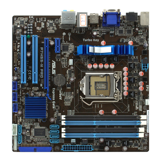
Page 21: Motherboard Layout
DDR3 DIMM slots 1-14 LPT connector (26-1 pin LPT) 1-27 Onboard LED (SB_PWR) Digital audio connector (4-1 pin SPDIF_OUT) 1-29 Clear RTC RAM (3-pin CLRTC) 1-24 Front panel audio connector (10-1 pin AAFP) 1-26 Serial ATA connectors (7-pin SATA1-6) 1-29 ASUS P7H55-M/USB3... -
Page 22: Central Processing Unit (Cpu)
Contact your retailer immediately if the PnP cap is missing, or if you see any damage to the PnP cap/socket contacts/motherboard components. ASUS will shoulder the cost of repair only if the damage is shipment/transit-related. • Keep the cap after installing the motherboard. ASUS will process Return Merchandise Authorization (RMA) requests only if the motherboard comes with the cap on the LGA1156 socket. - Page 23 CPU notches. The CPU fits in only one correct orientation. DO NOT force the CPU into the socket to prevent bending Gold the connectors on the socket and triangle damaging the CPU! mark Alignment keys ASUS P7H55-M/USB3 1-10...
- Page 24 Apply some Thermal Interface Material to the exposed area of the CPU that the heatsink will be in contact with, ensuring that it is spread in an even thin layer. Some heatsinks come with pre- applied thermal paste. If so, skip this step.
-
Page 25: Installing The Cpu Heatsink And Fan
The type of CPU heatsink and fan assembly may differ, but the installation steps and functions should remain the same. The illustration above is for reference only. ASUS P7H55-M/USB3 1-12... -
Page 26: Uninstalling The Cpu Heatsink And Fan
Connect the CPU fan cable to the connector on the motherboard labeled CPU_FAN. CPU_FAN P7H55-M/USB3 CPU fan connector Do not forget to connect the CPU fan connector! Hardware monitoring errors can occur if you fail to plug this connector. 1.6.3... -
Page 27: System Memory
DDR2 DIMM socket. DDR3 modules are developed for better performance with less power consumption. The figure illustrates the location of the DDR3 DIMM sockets: Channel Sockets Channel A DIMM_A1 and DIMM_A2 Channel B DIMM_B1 and DIMM_B2 P7H55-M/USB3 240-pin DDR3 DIMM sockets ASUS P7H55-M/USB3 1-14... -
Page 28: Memory Configurations
• Hyper DIMM support is subject to the physical characteristics of individual CPUs. • According to Intel spec definition, DDR3 1600+ is supported for one DIMM per channel only. ASUS exclusively provides two DDR3 1600+ DIMM support for each memory channel. - Page 29 P7H55-M/USB3 Motherboard Qualified Vendors Lists (QVL) DDR3-1600 MHz capability for Lynnfield CPU (2.66 GHz) DIMM socket support Chip Chip (Optional) Vendor Part No Size Timing Voltage Brand A-Data AD31600E001GM(O)U3K 3072MB 8-8-8-24 1.65V-1.85V • • • (Kit of 3) A-Data AD31600E002GU(XMP)
- Page 30 DDR3-1600 MHz capability for Lynnfield CPU (2.88 GHz and 2.93 GHz) DIMM socket support Chip Chip (Optional) Vendor Part No. Size SS/DS Timing Voltage Brand A-Data AD31600E001 3072MB 8-8-8-24 1.65V- • • • GM(O)U3K (Kit of 3) 1.85V A-Data AD31600X002 4096MB 7-7-7-20 1.75-...
- Page 31 • (low voltage) G.SKILL F3-10600CL7D-2GBPI 1024MB G.SKILL • • • (XMP) G.SKILL F3-10600CL8D-2GBHK 1024MB G.SKILL • • • G.SKILL F3-10600CL9D-2GBPK 1024MB G.SKILL • • • G.SKILL F3-10666CL7T-3GBPK 3072MB 7-7-7-18 1.5~ • • • (Kit of 3) 1.6V ASUS P7H55-M/USB3 1-18...
- Page 32 DDR3-1800 MHz capability for Lynnfield CPU (2.66 GHz) DIMM socket support (Optional) Chip Chip Vendor Part No Size Timing Voltage Brand OCZ3G18002GK 2048MB “9-9- 1.9V • • (Kit of 2) 9-27 QCZ3P18004GK 4096MB 8-8-8-27 1.9V • (Kit of 2) DDR3-1866 MHz capability for Lynnfield CPU (2.66 GHz) DIMM socket support (Optional) Chip...
- Page 33 • 2GBPI(XMP) G.SKILL F3-10600CL8D-2GBHK 1024MB G.SKILL • • • G.SKILL F3-10600CL9D-2GBPK 1024MB G.SKILL • • • G.SKILL F3-10666CL7T-3GBPK 3072MB 7-7-7-18 1.5~1.6V • • • (Kit of 3) G.SKILL F3-10666CL9T-3GBNQ 3072MB 9-9-9-24 1.5~1.6V • • (Kit of 3) ASUS P7H55-M/USB3 1-20...
- Page 34 • The QVL for the Clarkdale CPU is not included in this manual. You can get it from the ASUS website at www.asus.com • Visit the ASUS website at www.asus.com for the latest QVL. 1-21 Chapter 1: Product introduction...
-
Page 35: Installing A Dimm
Press the retaining clip outward to unlock the DIMM. Support the DIMM lightly with your fingers when pressing the retaining clip. The DIMM might get damaged when it flips out with extra force. Remove the DIMM from the socket. ASUS P7H55-M/USB3 1-22... -
Page 36: Expansion Slots
Expansion slots In the future, you may need to install expansion cards. The following sub-sections describe the slots and the expansion cards that they support. Unplug the power cord before adding or removing expansion cards. Failure to do so may cause you physical injury and damage motherboard components. -
Page 37: Jumpers
Normal Clear RTC (Default) P7H55-M/USB3 Clear RTC RAM To erase the RTC RAM: 1. Turn OFF the computer and unplug the power cord. 2. Move the jumper cap from pins 1-2 (default) to pins 2-3. Keep the cap on pins 2-3 for about 5-10 seconds, then move the cap back to pins 1-2. -
Page 38: Connectors
1.10 Connectors 1.10.1 Rear panel connectors PS/2 Keyboard/Mouse Combo port (purple). This port is for a PS/2 keyboard or PS/2 mouse. LAN (RJ-45) port. This port allows Gigabit connection to a Local Area Network (LAN) through a network hub. Refer to the table below for the LAN port LED indications. LAN port LED indications Speed Activity Link... -
Page 39: Internal Connectors
Legacy AC’97 pin definition compliant definition P7H55-M/USB3 Analog front panel connector • We recommend that you connect a high-definition front panel audio module to this connector to avail of the motherboard’s high-definition audio capability. • If you want to connect a high-definition front panel audio module to this connector, set the Front Panel Type item in the BIOS setup to [HD Audio]. - Page 40 The system may become unstable or may not boot up if the power is inadequate. • If you are uncertain about the minimum power supply requirement for your system, refer to the Recommended Power Supply Wattage Calculator at http://support.asus. com/PowerSupplyCalculator/PSCalculator.aspx?SLanguage=en-us for details. 1-27...
- Page 41 These are not jumpers! Do not place jumper caps on the fan connectors! • Only the 4-pin CPU fan supports the ASUS Q-FAN feature. • The CPU_FAN connector supports a CPU fan of maximum 2A (24 W) fan power.
- Page 42 S/PDIF Out module cable to this connector, then install the module to a slot opening at the back of the system chassis. SPDIF_OUT P7H55-M/USB3 Digital audio connector The S/PDIF module is purchased separately. Serial ATA connectors (7-pin SATA1-6) These connectors are for the Serial ATA signal cables for Serial ATA 3Gb/s hard disk and optical disk drives.
-
Page 43: Usb 2.0 Connectors
480 Mbps connection speed. USB1112 USB910 USB78 PIN 1 PIN 1 PIN 1 P7H55-M/USB3 USB2.0 connectors Never connect a 1394 cable to the USB connectors. Doing so will damage the motherboard! The USB module cable is purchased separately. ASUS P7H55-M/USB3 1-30... -
Page 44: System Panel Connector
IDE_LED PWRSW RESET * Requires an ATX power supply P7H55-M/USB3 System panel connector • System power LED (2-pin PLED) This 2-pin connector is for the system power LED. Connect the chassis power LED cable to this connector. The system power LED lights up when you turn on the system power, and blinks when the system is in sleep mode. -
Page 45: Software Support
Place the Support DVD to the optical drive. If Autorun is enabled in your computer, the DVD automatically displays the Specials screen which contains the unique feature of ASUS motherboard. Click Drivers, Utilities, Make Disk, Manual, and Contact tabs to display their respective menus. - Page 46 1-33 Chapter 1: Product introduction...
-
Page 47: Chapter 2: Bios Information
BIOS in the future. Copy the original motherboard BIOS using the ASUS Update utility. 2.1.1 ASUS Update utility The ASUS Update is a utility that allows you to manage, save, and update the motherboard BIOS in Windows environment. ®... -
Page 48: Asus Ez Flash 2
Follow the onscreen instructions to complete the updating process. 2.1.2 ASUS EZ Flash 2 The ASUS EZ Flash 2 feature allows you to update the BIOS without using an OS-based utility. Before you start using this utility, download the latest BIOS file from the ASUS website at www.asus.com. -
Page 49: Asus Crashfree Bios
2.1.3 ASUS CrashFree BIOS The ASUS CrashFree BIOS is an auto recovery tool that allows you to restore the BIOS file when it fails or gets corrupted during the updating process. You can restore a corrupted BIOS file using the motherboard support DVD or a removable device that contains the updated BIOS file. -
Page 50: Backing Up The Current Bios
Insert the USB flash drive with the latest BIOS file and BIOS Updater to the USB port. Boot your computer. When the ASUS Logo appears, press <F8> to show the BIOS Boot Device Select Menu. Insert the support DVD into the optical drive and select the optical drive as the boot device. - Page 51 Update ROM Saving BIOS: Updating the BIOS file To update the BIOS file using BIOS Updater At the FreeDOS prompt, type bupdater /pc /g and press <Enter>. The BIOS Updater screen appears as below. Update ROM Press <Tab> to switch between screen fields and use the <Up/Down/Home/End> keys to select the BIOS file and press <Enter>.
-
Page 52: Bios Setup Program
• The BIOS setup screens shown in this section are for reference purposes only, and may not exactly match what you see on your screen. • Visit the ASUS website at www.asus.com to download the latest BIOS file for this motherboard. -
Page 53: Bios Menu Screen
2.2.1 BIOS menu screen v02.61 (C)Copyright 1985-2010, American Megatrends, Inc. 2.2.2 Menu bar The menu bar on top of the screen has the following main items: Main For changing the basic system configuration. Ai Tweaker For changing system performance settings Advanced For changing the advanced system settings. -
Page 54: Submenu Items
To change the value of a field, select it then press <Enter> to display a list of options. Refer to 2.2.7 Pop-up window. P7H55-M/USB3 BIOS Setup Version 0306 2.2.7... -
Page 55: System Time [Xx:xx:xx]
2.3.1 System Time [xx:xx:xx] Allows you to set the system time. 2.3.2 System Date [Day xx/xx/xxxx] Allows you to set the system date. 2.3.3 Language [English] Allows you to choose the BIOS language version from the options. Configuration options: [Chinese (Trad.)] [Chinese (Simp.)] [Japanese] [French] [Deutsch] [English] 2.3.4 SATA1~6 While entering Setup, the BIOS automatically detects the presence of SATA devices. -
Page 56: Storage Configuration
When set to [Disabled], the data transfer from and to the device occurs one sector at a time. Configuration options: [Disabled] [Auto] 2-10 ASUS P7H55-M/USB3... -
Page 57: System Information
PIO Mode [Auto] Selects the PIO mode. Configuration options: [Auto] [0] [1] [2] [3] [4] DMA Mode [Auto] Selects the DMA mode. Configuration options: [Auto] SMART Monitoring [Auto] Sets the Smart Monitoring, Analysis, and Reporting Technology. Configuration options: [Auto] [Disabled] [Enabled] 32Bit Data Transfer [Enabled] Enables or disables 32-bit data transfer. -
Page 58: Ai Tweaker Menu
Be cautious when changing the settings of the Ai Tweaker menu items. Incorrect field values can cause the system to malfunction. The configuration options for this chapter vary depending on the CPU and DIMM model you installed on the motherboard. P7H55-M/USB3 BIOS Setup Version 0306 Main Ai Tweaker... -
Page 59: Cpu Ratio Setting [Auto]
D.O.C.P. D.O.C.P. • When using DIMMs with a frequency higher than the Intel CPU spec, use this ASUS ® exclusive DRAM O.C. Profile function to overclock the DRAM. • Adjust BCLK frequency to obtain a better performance after applying the D.O.C.P. -
Page 60: Bclk Frequency [Xxx]
The values vary depending on your settings of the following sub-items: DRAM CAS# Latency [Auto] Configuration options: [Auto] [3 DRAM Clock] [4 DRAM Clock] ~ [11 DRAM Clock] DRAM RAS# to CAS# Delay [Auto] Configuration options: [Auto] [3 DRAM Clock] [4 DRAM Clock] ~ [15 DRAM Clock] 2-14 ASUS P7H55-M/USB3... - Page 61 DRAM RAS# PRE Time [Auto] Configuration options: [Auto] [3 DRAM Clock] [4 DRAM Clock] ~ [15 DRAM Clock] DRAM RAS# ACT Time [Auto] Configuration options: [Auto] [3 DRAM Clock] [4 DRAM Clock] ~ [31 DRAM Clock] DRAM RAS# to RAS# Delay [Auto] Configuration options: [Auto] [1 DRAM Clock] ~ [7 DRAM Clock] DRAM REF Cycle Time [Auto] Configuration options: [Auto] [48 DRAM Clock] [60 DRAM Clock] [72 DRAM Clock]...
-
Page 62: Cpu Differential Amplitude [Auto]
CPU voltage. The values range from 0.85V to 1.60V with a 0.00625V interval. Refer to the CPU documentation before setting the CPU Vcore voltage. Setting a high VCore voltage may damage the CPU permanently, and setting a low VCore voltage may make the system unstable. 2-16 ASUS P7H55-M/USB3... -
Page 63: Imc Voltage [Auto]
2.4.15 IMC Voltage [Auto] Allows you to set the CPU Integrated Memory Controller voltage. The values range from 1.10V to 1.45V with a 0.00625V interval. 2.4.16 DRAM Voltage [Auto] Allows you to set the DRAM voltage. The values range from 1.500V to 2.205V. According to Intel CPU spec, DIMMs with voltage requirement over 1.65V may damage the CPU permanently. -
Page 64: Advanced Menu
The Advanced menu items allow you to change the settings for the CPU and other system devices. Be cautious when changing the settings of the Advanced menu items. Incorrect field values can cause the system to malfunction. P7H55-M/USB3 BIOS Setup Version 0306 Main Ai Tweaker... - Page 65 Adjacent Cache Line Prefetcher [Enabled] [Enabled] Enables the Adjacent Cache Line Prefetcher function. This item should be enabled in order to enable the L2 cache (MLC) Spatial Prefetcher for tuning performance of the specific application. [Disabled] Disables this function. Max CPUID Value Limit [Disabled] [Enabled] Allows legacy operating systems to boot even without support for CPUs with extended CPUID functions.
-
Page 66: Uncore Configuration
Configuration options: [Normal] [Bi-Directional] [EPP] [ECP] [ECP & EPP] ECP Mode DMA Channel [DMA3] Appears only when the Parallel Port Mode is set to [ECP] or [ECP & EPP]. This item allows you to set the Parallel Port ECP DMA. Configuration options: [DMA0] [DMA1] [DMA3] 2-20 ASUS P7H55-M/USB3... -
Page 67: Usb Configuration
EPP Version [1.9] Appears only when the Parallel Port Mode is set to [EPP] or [ECP & EPP]. Configuration options: [1.9] [1.7] Parallel Port IRQ [IRQ7] Allows you to select parallel port IRQ. Configuration options: [IRQ5] [IRQ7] 2.5.4 USB Configuration The items in this menu allows you to change the USB-related features. -
Page 68: Pcipnp
[Enabled] [Disabled] Power menu The Power menu items allow you to change the settings for the Advanced Power Management (APM). Select an item then press <Enter> to display the configuration options. P7H55-M/USB3 BIOS Setup Version 0306 Main Ai Tweaker Advanced... -
Page 69: Acpi Apic Support [Enabled]
2.6.3 ACPI APIC Support [Enabled] [Disabled] When set to [Disabled], the system disable the Advanced Configuration and Power Interface (ACPI) support in the Advanced Programmable Interrupt Controller (APIC). [Enabled] When set to [Enabled], the ACPI APIC table pointer is included in the RSDT pointer list. -
Page 70: Hardware Monitor
Sets the maximum CPU fan duty cycle. When the CPU temperature reaches the upper limit, the CPU fan will operate at the maximum duty cycle. Configuration options: [20%] [30%] [40%] [50%] [60%] [70%] [80%] [90%] [100%] CPU Lower Temperature [40ºC/104ºF] Displays the lower limit of the CPU temperature. 2-24 ASUS P7H55-M/USB3... -
Page 71: Boot Menu
Configuration options: [Removable Dev.] [Hard Drive] [ATAPI CD-ROM] [Disabled] • To select the boot device during system startup, press <F8> when ASUS Logo appears. • To access Windows OS in Safe Mode, do any of the following: ®... -
Page 72: Boot Settings Configuration
Enables or disables the full screen logo display feature. Configuration options: [Disabled] [Enabled] Set this item to [Enabled] to use the ASUS MyLogo2™ feature. AddOn ROM Display Mode [Force BIOS] Sets the display mode for option ROM. Configuration options: [Force BIOS] [Keep Current] Bootup Num-Lock [On] Selects the power-on state for the NumLock. -
Page 73: Security
2.7.3 Security The Security menu items allow you to change the system security settings. Select an item then press <Enter> to display the configuration options. Change Supervisor Password Select this item to set or change the supervisor password. The Supervisor Password item on top of the screen shows the default Not Installed. -
Page 74: Tools Menu
Setup and booting the system. Configuration options: [Setup] [Always] Tools menu The Tools menu items allow you to configure options for special functions. Select an item then press <Enter> to display the submenu. P7H55-M/USB# BIOS Setup Version 0306 Main Ai Tweaker... -
Page 75: Ai Net 2
2.8.3 ASUS EZ Flash 2 Allows you to run ASUS EZ Flash 2. When you press <OK>, a confirmation message appears. Use the left/right arrow key to select between [Yes] or [No], then press <OK> to confirm your choice. See section 2.1.2 ASUS EZ Flash 2 for details. -
Page 76: Exit Menu
Exit menu The Exit menu items allow you to load the optimal or failsafe default values for the BIOS items, and save or discard your changes to the BIOS items. P7H55-M/USB# BIOS Setup Version 0306 Main Ai Tweaker Advanced Power... -
Page 77: Asus Contact Information
+1-510-739-3777 +1-510-608-4555 Web site usa.asus.com Technical Support Telephone +1-812-282-2787 Support fax +1-812-284-0883 Online support support.asus.com ASUS Computer GmbH (Germany and Austria) Address Harkort Str. 21-23, D-40880 Ratingen, Germany +49-2102-959911 Web site www.asus.de Online contact www.asus.de/sales Technical Support Telephone (Component) +49-1805-010923*...