Table of Contents
Advertisement
Quick Links
Advertisement
Table of Contents

Related Manuals for Asus P7H55-M LX USB3


Summary of Contents for Asus P7H55-M LX USB3
- Page 1 P7H55-M LX/USB3...
- Page 2 Product warranty or service will not be extended if: (1) the product is repaired, modified or altered, unless such repair, modification of alteration is authorized in writing by ASUS; or (2) the serial number of the product is defaced or missing.
-
Page 3: Table Of Contents
Support DVD information ..........1-15 Chapter 2 BIOS information Managing and updating your BIOS ..........2-1 2.1.1 ASUS Update ..............2-1 2.1.2 ASUS EZ Flash 2 ............2-2 2.1.3 ASUS BIOS Updater ............2-3 2.1.4 ASUS CrashFree BIOS 3 ..........2-6... - Page 4 2.6.3 Security ................. 2-18 Tools menu ................. 2-19 2.7.1 AI NET 2................ 2-19 2.7.2 ASUS EZ Flash 2 ............2-19 2.7.3 IO Level up [Disabled] ........... 2-19 Exit menu ..................2-20 P7H55-M LX/USB3 motherboard installation notices ......2-21 Intel LGA1156 processor and chipset combination instruction ... 2-21 ®...
-
Page 5: Notices
Complying with the REACH (Registration, Evaluation, Authorisation, and Restriction of Chemicals) regulatory framework, we published the chemical substances in our products at ASUS REACH website at http://csr.asus.com/english/REACH.htm. DO NOT throw the motherboard in municipal waste. This product has been designed to enable proper reuse of parts and recycling. -
Page 6: Safety Information
Safety information Electrical safety • To prevent electric shock hazard, disconnect the power cable from the electric outlet before relocating the system. • When adding or removing devices to or from the system, ensure that the power cables for the devices are unplugged before the signal cables are connected. If possible, disconnect all power cables from the existing system before you add a device. -
Page 7: Conventions Used In This Guide
Refer to the following sources for additional information and for product and software updates. ASUS websites The ASUS website provides updated information on ASUS hardware and software products. Refer to the ASUS contact information. Optional documentation Your product package may include optional documentation, such as warranty flyers, that may have been added by your dealer. -
Page 8: P7H55-M Lx/Usb3 Specifications Summary
Memory Dual-channel memory architecture 2 x DIMM, max. 8GB, DDR3 1333/1066 MHz, non-ECC, un- buffered memory * Refer to www.asus.com for the latest Memory QVL (Qualified Vendors Lists). When you install a total memory of 4GB capacity or more, Windows 32-bit operating system may only recognize less ®... - Page 9 1 x I/O shield 1 x User Manual 1 x Support DVD Support DVD Drivers ASUS Utilities ASUS Update Anti-virus software (OEM version) Form factor uATX form factor: 9.6 in x 7.8 in (24.4 cm x 19.8 cm) * Specifications are subject to change without notice.
-
Page 10: Chapter 1 Product Introduction
Chapter 1 Product introduction Thank you for buying an ASUS P7H55-M LX/USB3 motherboard! ® Before you start installing the motherboard, and hardware devices on it, check the items in your motherboard package. Refer to page ix for the list of accessories. -
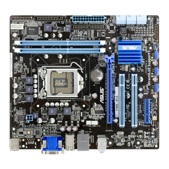
Page 11: Motherboard Overview
11. Serial port connectors (10-1 pin COM1) 1-14 5. Serial ATA connectors (7-pin SATA1-6) 1-10 12. Front panel audio connector (10-1 pin AAFP) 1-13 6. Clear RTC RAM (3-pin CLRTC) 13. Onboard LED (SB_PWR) 7. System panel connector (10-1 pin F_PANEL) 1-11 ASUS P7H55-M LX/USB3... -
Page 12: Central Processing Unit (Cpu)
Contact your retailer immediately if the PnP cap is missing, or if you see any damage to the PnP cap/socket contacts/motherboard components. ASUS will shoulder the cost of repair only if the damage is shipment/transit-related. • Keep the cap after installing the motherboard. ASUS will process Return Merchandise Authorization (RMA) requests only if the motherboard comes with the cap on the LGA1156 socket. -
Page 13: Memory Configurations
1.65V • • AL8F8G73D-DG1 DS PSC A3P1GF3DGF928M9B05 8-8-8-24 1.5V • • SAMSUNG M378B2873FHS-CH9 SS SAMSUNG K4B1G0846F • • SAMSUNG M378B5673FH0-CH9 DS SAMSUNG K4B1G0846F • • Super Talent W1333UX6GM 6GB(3x 2GB) DS Micron 0BF27D9KPT 9-9-9-24 1.5V • • ASUS P7H55-M LX/USB3... -
Page 14: Memory Configuration
• A*: Supports one module inserted into any slot as Single-channel memory configuration. • B*: Supports one pair of modules inserted into both the slots as one pair of Dual-channel memory configuration. Visit the ASUS website at www.asus.com for the latest QVL. Chapter 1: Product introduction... -
Page 15: Expansion Slots
This motherboard supports PCI Express x4 network cards, SCSI cards and other cards that comply with the PCI Express specifications. 1.5.5 PCI Express x16 slot This motherboard supports PCI Express x16 graphics cards that comply with the PCI Express specifications. ASUS P7H55-M LX/USB3... -
Page 16: Clear Rtc Ram
Jumpers Clear RTC RAM (3-pin CLRTC) This jumper allows you to clear the Real Time Clock (RTC) RAM in CMOS. You can clear the CMOS memory of date, time, and system setup parameters by erasing the CMOS RTC RAM data. The onboard button cell battery powers the RAM data in CMOS, which include system setup information such as system passwords. -
Page 17: Connectors
Pink (Rear panel) Mic In Mic In Bass/Center Bass/Center Lime (Front panel) Side Speaker Out To configure an 8-channel audio output: Use a chassis with HD audio module in the front panel to support an 8-channel audio output. ASUS P7H55-M LX/USB3... -
Page 18: Internal Connectors
USB 2.0 ports 1 and 2. These two 4-pin Universal Serial Bus (USB) ports connect to USB 2.0/1.1 devices. USB 3.0 ports 3 and 4. These two 9-pin Universal Serial Bus (USB) ports connect to USB 3.0/2.0 devices. • DO NOT connect a keyboard / mouse to any USB 3.0 port when installing Windows ®... - Page 19 XP Service Pack 2 or later version before using Serial ATA. ® Digital audio connector (4-1 pin SPDIF_OUT) This connector is for an additional Sony/Philips Digital Interface (S/PDIF) port. P7H55-M LX/USB3 SPDIF_OUT P7H55-M LX/USB3 Digital audio connector The S/PDIF module is purchased separately. ASUS P7H55-M LX/USB3 1-10...
-
Page 20: Cpu And Chassis Fan Connectors
CPU and Chassis fan connectors (4-pin CPU_FAN, 3-pin CHA_FAN) Connect the fan cables to the fan connectors on the motherboard, making sure that the black wire of each cable matches the ground pin of the connector. DO NOT forget to connect the fan cables to the fan connectors. Insufficient air flow inside the system may damage the motherboard components. - Page 21 The system may become unstable or may not boot up if the power is inadequate. • If you are uncertain about the minimum power supply requirement for your system, refer to the Recommended Power Supply Wattage Calculator at http://support.asus. com/PowerSupplyCalculator/PSCalculator.aspx?SLanguage=en-us for details. ASUS P7H55-M LX/USB3...
-
Page 22: Front Panel Audio Connector
Front panel audio connector (10-1 pin AAFP) This connector is for a chassis-mounted front panel audio I/O module that supports either High Definition Audio or AC`97 audio standard. Connect one end of the front panel audio I/O module cable to this connector. AAFP PIN 1 PIN 1... - Page 23 The connector is for a serial (COM) port. Connect the serial port module cable to the connector, then install the module to a slot opening at the back of the system chassis. The serial port bracket (COM1) is purchased separately. COM1 PIN 1 P7H55-M LX/USB3 P7H55-M LX/USB3 Serial port (COM1) connector ASUS P7H55-M LX/USB3 1-14...
-
Page 24: Software Support
Place the Support DVD into the optical drive. The DVD automatically displays the Drivers menu if the Autorun function is enabled on your computer. The contents of the Support DVD are subject to change at any time without notice. Visit the ASUS website at www.asus.com for updates. Click an icon to display Support... -
Page 25: Chapter 2 Bios Information
BIOS in the future. Copy the original motherboard BIOS using the ASUS Update utility. 2.1.1 ASUS Update The ASUS Update is a utility that allows you to manage, save, and update the motherboard BIOS in Windows environment. ®... -
Page 26: Asus Ez Flash 2
Follow the onscreen instructions to complete the updating process. 2.1.2 ASUS EZ Flash 2 The ASUS EZ Flash 2 feature allows you to update the BIOS without using an OS-based utility. Before you start using this utility, download the latest BIOS file from the ASUS website at www.asus.com. -
Page 27: Asus Bios Updater
2.1.3 ASUS BIOS Updater The ASUS BIOS Updater allows you to update BIOS in DOS environment. This utility also allows you to copy the current BIOS file that you can use as a backup when the BIOS fails or gets corrupted during the updating process. - Page 28 When the Make Disk menu appears, select the FreeDOS command prompt item by pressing the item number. At the FreeDOS prompt, type d: and press <Enter> to switch the disk from Drive C (optical drive) to Drive D (USB flash drive). Welcome to FreeDOS (http://www.freedos.org)! C:\>d: D:\>...
-
Page 29: Updating The Bios File
Select the Load Setup Defaults item under the Exit BIOS menu. See section 2.8 Exit menu for details. • Ensure to connect all SATA hard disk drives after updating the BIOS file if you have disconnected them. ASUS P7H55-M LX/USB3... -
Page 30: Asus Crashfree Bios 3
2.1.4 ASUS CrashFree BIOS 3 ASUS CrashFree BIOS 3 is an auto recovery tool that allows you to restore the BIOS file when it fails or gets corrupted during the updating process. You can restore a corrupted BIOS file using the motherboard support DVD or a USB flash drive that contains the BIOS file. -
Page 31: Bios Setup Program
• The BIOS setup screens shown in this section are for reference purposes only, and may not exactly match what you see on your screen. • Visit the ASUS website at www.asus.com to download the latest BIOS file for this motherboard. -
Page 32: Main Menu
Main menu When you enter the BIOS Setup program, the Main menu screen appears, giving you an overview of the basic system information. P7H55-M LX/USB3 BIOS Setup Version 0205 Main Advanced Power Boot Tools Exit Use [ENTER], [TAB] or System Time [00:31:48] [SHIFT-TAB] to select System Date... -
Page 33: Storage Configuration
Sets the configuration for the Serial ATA connectors supported by the Southbridge chip. Configuration options: [IDE] [AHCI] Due to Intel chipset driver support regulation, the AHCI mode is not supported in Windows XP environment. The AHCI mode is only supported by Windows Vista/7 with OS built-in driver. ASUS P7H55-M LX/USB3... -
Page 34: System Information
2.3.6 System Information This menu gives you an overview of the general system specifications. The BIOS automatically detects the items in this menu. Bios Information Displays the auto-detected BIOS information. Processor Displays the auto-detected CPU specification. System Memory Displays the auto-detected system memory. Advanced menu The Advanced menu items allow you to change the settings for the CPU and other system devices. -
Page 35: Cpu Configuration
Virtualization Technology. Virtualization enhanced by Intel ® ® Virtualization Technology allows a platform to run multiple operating systems and applications in independent partitions. With virtualization, one computer system can function as multiple virtual systems. Configuration options: [Enabled] [Disabled] ASUS P7H55-M LX/USB3 2-11... - Page 36 CPU TM function [Enabled] Enables or disables Intel CPU Thermal Monitor (TM) function, a CPU overheating protection ® function. When enabled, the CPU core frequency and voltage are reduced when the CPU overheats. Configuration options: [Disabled] [Enabled] Execute-Disable Bit Capability [Enabled] Allows you to enable or disable the No-Execution Page Protection Technology.
-
Page 37: Chipset
Allows you to enable or disable the boot ROM in the onboard LAN controller. This item appears only when the Onboard LAN item is set to [Enabled]. Configuration options: [Disabled] [Enabled] Serial Port1 Address [3F8/IRQ4] Allows you to select the Serial Port1 base address. Configuration options: [Disabled] [3F8/IRQ4] [2F8/IRQ3] [3E8/IRQ4] [2E8/IRQ3] ASUS P7H55-M LX/USB3 2-13... -
Page 38: Usb Configuration
2.4.4 USB Configuration The items in this menu allows you to change the USB-related features. Select an item then press <Enter> to display the configuration options. The Module Version and USB Devices Enabled items show the auto-detected values. If no USB device is detected, the item shows None. -
Page 39: Intel Vt-D Configuration
Application-Specific Integrated Circuit (ASIC). When set to Enabled, the ACPI APIC table pointer is included in the RSDT pointer list. Configuration options: [Disabled] [Enabled] 2.5.4 Anti Surge Support [Disabled] Allows you to enable or disable the Anti Surge function. Configuration options: [Disabled] [Enabled] ASUS P7H55-M LX/USB3 2-15... -
Page 40: Apm Configuration
2.5.5 APM Configuration Restore on AC Power Loss [Power Off] When set to [Power Off], the system goes into off state after an AC power loss. When set to [Power On], the system goes on after an AC power loss. When set to [Last State], the system goes into either off or on state, whatever the system state was before the AC power loss. -
Page 41: Boot Menu
Configuration options: [Removable Dev.] [Hard Drive] [ATAPI CD- ROM] [Disabled] • To select the boot device suring system startup, press <F8> when ASUS Logo appears. • To access Windows OS in Safe Mode, do any of the following: ®... -
Page 42: Security
AddOn ROM Display Mode [Force BIOS] Sets the display mode for option ROM. Configuration options: [Force BIOS] [Keep Current] Bootup Num-Lock [On] Allows you to select the power-on state for the NumLock. Configuration options: [Off] [On] Wait For ‘F1’ If Error [Enabled] When set to Enabled, the system waits for the F1 key to be pressed when error occurs. -
Page 43: Tools Menu
2.7.2 ASUS EZ Flash 2 Allows you to run ASUS EZ Flash 2. When you press <Enter>, a confirmation message appears. Use the left/right arrow key to select between [Yes] or [No], then press <Enter> to confirm your choice. Please see section 2.1.2 for details. -
Page 44: Exit Menu
Exit menu The Exit menu items allow you to load the optimal or failsafe default values for the BIOS items, and save or discard your changes to the BIOS items. P7H55-M LX/USB3 BIOS Setup Version 0205 Main Advanced Power Boot Tools Exit Exit Options... -
Page 45: P7H55-M Lx/Usb3 Motherboard Installation Notices
PCIe x16_2 (black)* No limitation No limitation PCIe x16_3* (black) No limitation No limitation * The color of the PCIe x16_2 slot varies by model. ** The PCIe x16_2 slot can work at maximum x8 link only. ASUS P7H55-M LX/USB3 2-21... -
Page 46: Asus Contact Information
+1-510-739-3777 +1-510-608-4555 Web site usa.asus.com Technical Support Telephone +1-812-282-2787 Support fax +1-812-284-0883 Online support support.asus.com ASUS COMPUTER GmbH (Germany and Austria) Address Harkort Str. 21-23, D-40880 Ratingen, Germany +49-2102-959911 Web site www.asus.de Online contact www.asus.de/sales Technical Support Telephone (Component) +49-1805-010923*... - Page 47 ASUS P7H55-M LX/USB3 2-23...
- Page 48 +1-510-608-4555 Web site usa.asus.com Technical Support Telephone +1-812-282-2787 Support fax +1-812-284-0883 Online support support.asus.com ASUS COMPUTER GmbH (Germany and Austria) Address Harkort Str. 21-23, D40880 Ratingen, Germany +49-2102-9599-11 Online contact www.asus.com.de/sales Technical Support Component Telephone +49-1805-010923 System/Notebook /Eee/LCD Telephone +49-1805-010920...