Table of Contents
Advertisement
Quick Links
Advertisement
Table of Contents

Related Manuals for Asus P7P55D-E - Premium Motherboard - ATX


Summary of Contents for Asus P7P55D-E - Premium Motherboard - ATX
- Page 1 P7P55D-E...
- Page 2 Product warranty or service will not be extended if: (1) the product is repaired, modified or altered, unless such repair, modification of alteration is authorized in writing by ASUS; or (2) the serial number of the product is defaced or missing.
-
Page 3: Table Of Contents
Welcome! ....................1-1 Package contents..................1-1 Special features..................1-2 1.3.1 Product highlights................ 1-2 1.3.2 ASUS Xtreme Design—Hybrid Processor ........1-3 1.3.3 ASUS Xtreme Design—Hybrid Phase ........1-3 1.3.4 ASUS Xtreme Design—Hybrid OS ..........1-3 1.3.5 ASUS Exclusive Features ............1-4... - Page 4 BIOS setup Knowing BIOS .................... 3-1 Updating BIOS .................... 3-1 3.2.1 ASUS Update utility..............3-2 3.2.2 ASUS EZ Flash 2 utility ............... 3-4 3.2.3 ASUS BIOS Updater ..............3-5 3.2.4 ASUS CrashFree BIOS 3 utility........... 3-8 BIOS setup program .................. 3-8 3.3.1...
- Page 5 Contents 3.5.7 DRAM Frequency ..............3-17 3.5.8 QPI Frequency ................. 3-18 3.5.9 ASUS/3rd Party UI Priority ............3-18 3.5.10 OC Tuner................... 3-18 3.5.11 Start auto tuning ................ 3-18 3.5.12 DRAM Timing Control .............. 3-18 3.5.13 CPU Differential Amplitude ............3-20 3.5.14...
- Page 6 Contents Tools menu ....................3-36 3.9.1 ASUS O.C. Profile ..............3-36 3.9.2 AI NET 2 ..................3-37 3.9.3 ASUS EZ Flash 2 ..............3-37 3.9.4 Express Gate ................3-38 3.9.5 IO Levelup ................3-38 3.10 Exit menu ....................3-39 Chapter 4: Software support Installing an operating system ..............
-
Page 7: Notices
Complying with the REACH (Registration, Evaluation, Authorisation, and Restriction of Chemicals) regulatory framework, we published the chemical substances in our products at ASUS REACH website at http://green.asus.com/english/REACH.htm. DO NOT throw the motherboard in municipal waste. This product has been designed to enable proper reuse of parts and recycling. -
Page 8: Safety Information
Safety information Electrical safety • To prevent electrical shock hazard, disconnect the power cable from the electrical outlet before relocating the system. • When adding or removing devices to or from the system, ensure that the power cables for the devices are unplugged before the signal cables are connected. If possible, disconnect all power cables from the existing system before you add a device. -
Page 9: About This Guide
Where to find more information Refer to the following sources for additional information and for product and software updates. ASUS websites The ASUS website provides updated information on ASUS hardware and software products. Refer to the ASUS contact information. Optional documentation Your product package may include optional documentation, such as warranty flyers, that may have been added by your dealer. -
Page 10: Conventions Used In This Guide
Conventions used in this guide To ensure that you perform certain tasks properly, take note of the following symbols used throughout this manual. DANGER/WARNING: Information to prevent injury to yourself when trying to complete a task. CAUTION: Information to prevent damage to the components when trying to complete a task. -
Page 11: P7P55D-E Specifications Summary
* Hyper DIMM support is subject to the physical characteristics of individual CPUs. Some hyper DIMMs only support one DIMM per channel. Please refer to Memory QVL for details. ** Refer to www.asus.com or this user manual for the Memory QVL (Qualified Vendors Lists) Expansion Slots 2 x PCI Express 2.0 x 16 slots... - Page 12 P7P55D-E specifications summary ASUS Q-Design ASUS Q-LED (CPU, DRAM, VGA, Boot Device LED) ASUS Q-Slot ASUS Q-DIMM ASUS Unique Features ASUS IO Level UP for Ultra Performance - True USB 3.0 or True SATA 6Gb/s Support ASUS Xtreme Design ASUS Hybrid Processor—TurboV EVO...
- Page 13 1 x IO Level UP button BIOS Features 16 Mb Flash ROM, AMI BIOS, PnP, DMI 2.0, WfM 2.0, SM BIOS 2.5, ACPI 2.0a, Multi-language BIOS, ASUS EZ Flash 2, ASUS CrashFree BIOS 3 Manageability WfM 2.0, DMI 2.0, WOL by PME, WOR by PME, PXE...
-
Page 15: Chapter 1: Product Introduction
® The motherboard delivers a host of new features and latest technologies, making it another standout in the long line of ASUS quality motherboards! Before you start installing the motherboard, and hardware devices on it, check the items in your package with the list below. -
Page 16: Special Features
Special features 1.3.1 Product highlights Intel LGA1156 Lynnfield / Clarkdale Processor Ready ® This motherboard supports the latest Intel Lynnfield / Clarkdale processors in LGA1156 ® package, which has memory and PCI Express controller integrated to support 2-channel (4 DIMMs) DDR3 memory and 16 PCI Express 2.0 lanes, enabling higher graphics performance. -
Page 17: Asus Xtreme Design-Hybrid Processor
ASUS Xtreme Design—Hybrid OS ASUS Express Gate 0 to Internet in seconds! Express Gate is an ASUS exclusive OS that provides you with quick access to the Internet and key applications without entering the Windows OS. Refer to page 3-38 and 4-7 for ®... -
Page 18: Asus Exclusive Features
ASUS EPU System Level Energy Saving The new ASUS EPU—the world’s first power saving engine, has been upgraded to a new 6 engine version, which provides total system power savings by detecting current PC loadings and intelligently moderating power in real-time. With auto phase switching for components... -
Page 19: Chapter 2: Hardware Information
Before you install or remove any component, ensure that the ATX power supply is switched off or the power cord is detached from the power supply. Failure to do so may cause severe damage to the motherboard, peripherals, or components. ASUS P7P55D-E... -
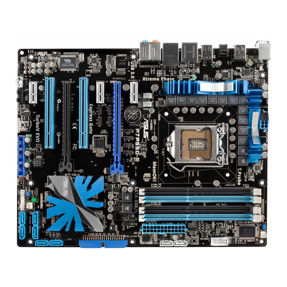
Page 20: Motherboard Overview
Motherboard overview 2.2.1 Motherboard layout Refer to 2.8 Connectors for more information about rear panel connectors and internal connectors. Chapter 2: Hardware information... -
Page 21: Layout Contents
USB connectors (10-1 pin USB910, USB1112, USB1314) 2-35 IO Level UP switch 2-25 IEEE 1394a port connector (10-1 pin IE1394_2) 2-36 Optical drive audio connector (4-pin CD) 2-35 Front panel audio connector (10-1 pin AAFP) 2-38 Digital audio connector (4-1 pin SPDIF_OUT) 2-38 ASUS P7P55D-E... -
Page 22: Placement Direction
2.2.3 Placement direction When installing the motherboard, ensure that you place it into the chassis in the correct orientation. The edge with external ports goes to the rear part of the chassis as indicated in the image below. 2.2.4 Screw holes Place nine screws into the holes indicated by circles to secure the motherboard to the chassis. -
Page 23: Central Processing Unit (Cpu)
Contact your retailer immediately if the PnP cap is missing, or if you see any damage to the PnP cap/socket contacts/motherboard components. ASUS will shoulder the cost of repair only if the damage is shipment/ transit-related. - Page 24 Lift the load lever in the direction of the arrow until the load plate is completely lifted. Load plate Remove the PnP cap from the CPU socket by lifting the tab only. PnP cap Cap tab Position the CPU over the socket, ensuring that the gold triangle is on the bottom-left corner of the socket, and then CPU notches...
- Page 25 Close the load plate (A), and then push down the load lever (B), ensuring that the front edge of the load plate slides under the retention knob (C). Insert the load lever under the retention tab. ASUS P7P55D-E...
-
Page 26: Installing The Cpu Heatsink And Fan
2.3.2 Installing the CPU heatsink and fan The Intel LGA1156 processor requires a specially designed heatsink and fan assembly to ® ensure optimum thermal condition and performance. • When you buy a boxed Intel ® processor, the package includes the CPU fan and heatsink assembly. -
Page 27: Uninstalling The Cpu Heatsink And Fan
Rotate each fastener counterclockwise. Pull up two fasteners at a time in a diagonal sequence to disengage the heatsink and fan assembly from the motherboard. Carefully remove the heatsink and fan assembly from the motherboard. ASUS P7P55D-E... -
Page 28: System Memory
System memory 2.4.1 Overview The motherboard comes with four Double Data Rate 3 (DDR3) Dual Inline Memory Modules (DIMM) sockets. A DDR3 module has the same physical dimensions as a DDR2 DIMM but is notched differently to prevent installation on a DDR2 DIMM socket. DDR3 modules are developed for better performance with less power consumption. -
Page 29: Memory Configurations
3.5 Ai Tweaker menu for manual memory frequency adjustment. • For system stability, use a more efficient memory cooling system to support a full memory load (4 DIMMs) or overclocking condition. ASUS P7P55D-E 2-11... - Page 30 P7P55D-E Motherboard Qualified Vendors Lists (QVL) DDR3-1067MHz capability for CPU at 2.66, 2.8 and 2.93GHz DIMM socket Chip Timing support (Optional) Vendor Part No. Size Chip NO. Voltage Brand Lable(Bios) CORSAIR CM3X1024-1066C7 1024MB DS Heat-Sink Package • • • Crucial CT12864BA1067.8FF 1024MB SS MICRON...
- Page 31 • Patriot PVT36G1333ELK 6144MB(Kit of 3) DS N/A Heat-Sink Package 9-9-9-24(1066-7-7-7-20) 1.65 • • • Silicon SP001GBLTU133S02 1024MB SS S-POWER I0YT3E0 9(1333-9-9-9-24) • • • Power Silicon SP002GBLTU133S02 2048MB DS S-POWER I0YT3E0 9(1333-9-9-9-24) • • • Power ASUS P7P55D-E 2-13...
- Page 32 P7P55D-E Motherboard Qualified Vendors Lists (QVL) DDR3-1600MHz capability for CPU at 2.66GHz DIMM socket Chip Timing support (Optional) Vendor Part No. Size Chip NO. Voltage Brand Dimm(Bios) A-DATA AD31600E001GMU 3072MB(Kit of 3) SS N/A Heat-Sink Package 8-8-8-24(1333-9-9-9-24) 1.65-1.85 • • •...
- Page 33 Patriot PVT36G1600ELK 6144MB(Kit of 3) DS N/A Heat-Sink Package 9-9-9-24(1066-7-7-7-20) 1.65 • • • Patriot PVT36G1600ELK 6144MB(Kit of 3) DS N/A Heat-Sink Package 9-9-9-24(1600-7-7-7-20) 1.65 • • • MFADR401PA0102(XMP) 2048MB DS SAMSUNG K4B1G08460 1066-8-8-8-20 • • • ASUS P7P55D-E 2-15...
- Page 34 P7P55D-E Motherboard Qualified Vendors Lists (QVL) DDR3-1625MHz capability for CPU at 2.66GHz DIMM socket Chip Timing support (Optional) Vendor Part No. Size SS/DS Chip NO. Voltage Brand Dimm(Bios) KINGSTON KHX13000D3LLK2/2GN(EPP) 2048MB(Kit of 2) Heat-Sink Package • • • KINGSTON KHX13000D3LLK2/2GX(XMP) 2048MB(Kit of 2) Heat-Sink Package •...
- Page 35 2GB(Kit of 2) SS Heat-Sink Package 8 • • OCZ3P20002GK(EPP) 2GB(Kit of 2) SS Heat-Sink Package 9 • • OCZ3P2000EB2GK 2GB(Kit of 2) SS Heat-Sink Package 9-8-8(1066-8-7-7-20) • • Gingle 9CAASS37AZZ01D1 DS N/A Heat-Sink Package 9-9-9-24 • • • ASUS P7P55D-E 2-17...
- Page 36 Hyper DIMM support is subject to the physical characteristics of individual CPUs. • According to Intel spec definition, DDR3-1600 is supported for one DIMM per channel only. ASUS exclusively provides two DDR3-1600 DIMM support for each memory channel. • According to Intel CPU spec, CPUs with a core frequency of 2.66G support the maximum DIMM frequency of up to DDR3-1333.
-
Page 37: Installing A Dimm
Press the retaining clip outward to unlock the DIMM. Support the DIMM lightly with your fingers when pressing the retaining clip. The DIMM might get damaged when it flips out with extra force. Remove the DIMM from the socket. ASUS P7P55D-E 2-19... -
Page 38: Expansion Slots
Expansion slots In the future, you may need to install expansion cards. The following subsections describe the slots and the expansion cards that they support. Ensure to unplug the power cord before adding or removing expansion cards. Failure to do so may cause you physical injury and damage motherboard components. -
Page 39: Interrupt Assignments
Levelup disabled or set shared to USB 3.0) SATA 6G Controller (IO shared Levelup set to SATA6G) JMicron ATA Controller shared 1394 Controller – – shared – – – – HD Audio – – – – – – shared – ASUS P7P55D-E 2-21... -
Page 40: Pci Slots
2.5.4 PCI slots The PCI slots support cards such as a LAN card, SCSI card, USB card, and other cards that comply with PCI specifications. Refer to the figure below for the location of the slot. 2.5.5 PCI Express x1 slots This motherboard supports PCI Express x1 network cards, SCSI cards, and other cards that comply with the PCI Express specifications. - Page 41 We recommend that you provide sufficient power when running CrossFireX™ mode. See page 2-39 for details. • Connect a chassis fan to the motherboard connector labeled CHA_FAN1/2 when using multiple graphics cards for better thermal environment. See page 2-37 for details. ASUS P7P55D-E 2-23...
-
Page 42: Onboard Switches
BIOS default settings. A messgae will appear during POST reminding you that the BIOS has been restored to its default settings. • We recommend that you download and update to the latest BIOS version from the ASUS website at www.asus.com after using the MemOK! function. 2-24 Chapter 2: Hardware information... - Page 43 Press the IO Level UP switch during POST will restart the system to apply speed changes. • If you press the IO Level UP switch in OS environment, you have to manually restart the system to apply speed changes. ASUS P7P55D-E 2-25...
-
Page 44: Jumpers
Jumpers Clear RTC RAM (3-pin CLRTC) This jumper allows you to clear the Real Time Clock (RTC) RAM in CMOS. You can clear the CMOS memory of date, time, and system setup parameters by erasing the CMOS RTC RAM data. The onboard button cell battery powers the RAM data in CMOS, which include system setup information such as system passwords. - Page 45 BIOS voltage settings before you change the setting of the jumper. • The system may need a better cooling system, such as a water cooling system, to maintain stability under high voltage settings. ASUS P7P55D-E 2-27...
-
Page 46: Connectors
Connectors 2.8.1 Rear panel connectors Rear panel connectors 1. PS/2 mouse port (green) 7. Optical S/PDIF Out port 2. USB 2.0 ports 1 and 2 8. External SATA port 3. USB 2.0 ports 3 and 4 9. IEEE 1394a port 4. -
Page 47: Audio I/O Connections
Mic In Orange – – Center/Subwoofer Center/Subwoofer Black – Rear Speaker Out Rear Speaker Out Rear Speaker Out Gray – – – Side Speaker Out 2.8.2 Audio I/O connections Audio I/O ports Connect to Headphone and Mic ASUS P7P55D-E 2-29... - Page 48 Connect to Stereo Speakers Connect to 2.1 channel Speakers Connect to 4.1 channel Speakers 2-30 Chapter 2: Hardware information...
- Page 49 Connect to 5.1 channel Speakers Connect to 7.1 channel Speakers ASUS P7P55D-E 2-31...
-
Page 50: Internal Connectors
2.8.3 Internal connectors IDE connector (40-1 pin PRI_EIDE) The onboard IDE connector is for the Ultra DMA 133/100/66 signal cable. There are three connectors on each Ultra DMA 133/100/66 signal cable: blue, black, and gray. Connect the blue connector to the motherboard’s IDE connector, then select one of the following modes to configure your device. - Page 51 The Serial ATA RAID feature (RAID 0, 1, 5, and 10) is available only if you are using Windows XP SP2 or later version. ® When using hot-plug and NCQ, set the Configure SATA as item in the BIOS to • [AHCI]. See section 3.4.2 Storage Configuration for details. ASUS P7P55D-E 2-33...
- Page 52 JMicron JMB363 Serial ATA connector (7-pin SATA_E1 [black]) ® This connector connects to a Serial ATA hard disk drive or optical disc drive via a Serial ATA signal cable. To enable hot-plugging, set the J-Micron Controller item in the BIOS setting to [AHCI Mode], and then reboot the system.
- Page 53 Never connect a 1394 cable to the USB connectors. Doing so will damage the motherboard! You can connect the front panel USB cable to the ASUS Q-Connector (USB, blue) first, and then install the Q-Connector (USB) to the USB connector onboard if your chassis supports front panel USB ports.
- Page 54 IEEE 1394a port connector (10-1 pin IE1394_2) This connector is for an IEEE 1394a port. Connect the IEEE 1394a module cable to this connector, then install the module to a slot opening at the back of the system chassis. Never connect a USB cable to the IEEE 1394a connector. Doing so will damage the motherboard! The IEEE 1394a module is purchased separately.
- Page 55 Only the CPU_FAN, CHA_FAN 1, and CHA_FAN 2 connectors support the FAN Xpert feature. • If you install two VGA cards, we recommend that you plug the rear chassis fan cable to the motherboard connector labeled CHA_FAN1 or CHA_FAN2 for better thermal environment. ASUS P7P55D-E 2-37...
- Page 56 Digital audio connector (4-1 pin SPDIF_OUT) This connector is for an additional Sony/Philips Digital Interface (S/PDIF) port(s). Connect the S/PDIF Out module cable to this connector, then install the module to a slot opening at the back of the system chassis. The S/PDIF module is purchased separately.
- Page 57 • If you are uncertain about the minimum power supply requirement for your system, refer to the Recommended Power Supply Wattage Calculator at http://support.asus. com/PowerSupplyCalculator/PSCalculator.aspx?SLanguage=en-us for details. • If you want to use two or more high-end PCI Express x16 cards, use a PSU with 1000W power or above to ensure the system stability.
-
Page 58: System Panel Connector 20-8 Pin Panel
System panel connector (20-8 pin PANEL) This connector supports several chassis-mounted functions. • System power LED (2-pin PLED) This 2-pin connector is for the system power LED. Connect the chassis power LED cable to this connector. The system power LED lights up when you turn on the system power, and blinks when the system is in sleep mode. -
Page 59: Asus Q-Connector (System Panel)
2.8.4. ASUS Q-Connector (system panel) Use the ASUS Q-Connector to connect/disconnect the chassis front panel cables. To install the ASUS Q-Connector Connect the front panel cables to the ASUS Q-Connector. Refer to the labels on the Q-Connector to know the detailed pin definitions, and then match them to their respective front panel cable labels. -
Page 60: Onboard Leds
Onboard LEDs POST State LEDs POST State LEDs check key components (CPU, DRAM, VGA card, and HDD) in sequence during motherboard booting process. If an error is found , the LED next to the error device will continue lighting until the problem is solved. This user-friendly design provides an intuitive way to locate the root problem within seconds. -
Page 61: Starting Up For The First Time
BIOS setting. Pressing the power switch for more than four seconds lets the system enter the soft-off mode regardless of the BIOS setting. Refer to section 3.7 Power Menu in Chapter 3 for details. ASUS P7P55D-E 2-43... - Page 62 2-44 Chapter 2: Hardware information...
-
Page 63: Chapter 3: Bios Setup
Refer to the corresponding sections for details on these utilities. Save a copy of the original motherboard BIOS file to a USB flash drive in case you need to restore the BIOS in the future. Copy the original motherboard BIOS using the ASUS Update utility. -
Page 64: Asus Update Utility
3.2.1 ASUS Update utility The ASUS Update is a utility that allows you to manage, save, and update the motherboard BIOS in Windows environment. The ASUS Update utility allows you to: ® • Save the current BIOS file • Download the latest BIOS file from the Internet •... -
Page 65: Updating Bios Through Bios File
Auto Select. Click Next. Next. Follow the onscreen instructions to complete the update process. The ASUS Update utility is capable of updating itself through the Internet. Always update the utility to avail all its features. Updating the BIOS through a BIOS file... -
Page 66: Asus Ez Flash 2 Utility
3.2.2 ASUS EZ Flash 2 utility The ASUS EZ Flash 2 feature allows you to update the BIOS without using an OS-based utility. Before you start using this utility, download the latest BIOS from the ASUS website at www. asus.com. -
Page 67: Asus Bios Updater
3.2.3 ASUS BIOS Updater The ASUS BIOS Updater allows you to update BIOS in DOS environment. This utility also allows you to copy the current BIOS file that you can use as a backup when the BIOS fails or gets corrupted during the updating process. - Page 68 Backing up the current BIOS To backup the current BIOS file using the BIOS Updater Ensure that the USB flash drive is not write-protected and has enough free space to save the file. At the FreeDOS prompt, type bupdater /o[filename] and press <Enter>. D:\>bupdater /oOLDBIOS1.rom Filename Extension The [filename] is any user-assigned filename with no more than eight alphanumeric...
- Page 69 Select the Load Setup Defaults item under the Exit BIOS menu. See Chaper 3 of your motherboard user manual for details. • Ensure to connect all SATA hard disk drives after updating the BIOS file if you have disconnected them. ASUS P7P55D-E...
-
Page 70: Asus Crashfree Bios 3 Utility
The BIOS file in the motherboard support DVD may be older than the BIOS file published on the ASUS official website. If you want to use the newer BIOS file, download the file at support.asus.com and save it to a USB flash drive. -
Page 71: Bios Menu Screen
For changing the advanced system settings Power For changing the advanced power management (APM) configuration Boot For changing the system boot configuration Tools For configuring options for special functions Exit For selecting the exit options and loading default settings ASUS P7P55D-E... -
Page 72: Navigation Keys
3.3.3 Navigation keys At the bottom right corner of a menu screen are the navigation keys for that particular menu. Use the navigation keys to select items in the menu and change the settings. The navigation keys may differ from one screen to another. 3.3.4 Menu items The highlighted item on the menu bar displays the specific items for that menu. -
Page 73: Main Menu
(C)Copyright 1985-2009, American Megatrends, Inc. The BIOS automatically detects the values of the dimmed items (Device, Vendor, Size, LBA Mode, Block Mode, PIO Mode, Async DMA, Ultra DMA, and SMART monitoring). These values are not user-configurable. ASUS P7P55D-E 3-11... - Page 74 Type [Auto] Allows you to select the type of SATA drive installed. [Not Installed] Select this option if no SATA drive is installed. [Auto] Allows automatic selection of the appropriate SATA device type. [CDROM] Select this option if you are specifically configuring a CD-ROM drive. [ARMD] Select [ARMD] (ATAPI Removable Media Device) if your device is a ZIP, LS-120, or MO drive.
-
Page 75: Storage Configuration
AHCI Settings Some SATA CD/DVD in AHCI mode need to wait ready longer. SATA Port1 [Not Detected] SATA Port2 [Not Detected] SATA Port3 [Not Detected] SATA Port4 [Not Detected] SATA Port5 [Not Detected] SATA Port6 [Not Detected] ASUS P7P55D-E 3-13... -
Page 76: System Information
SATA Port1–6 [XXXX] Displays the status of auto-detection of SATA devices. BIOS SETUP UTILITY Main Select the type SATA Port1 of devices connected Device :Not Detected to the system. SATA Port1 [Auto] SMART Monitoring [Enabled] SATA Port1 [Auto] Allows you to select the type of device connected to the system. Configuration options: [Auto] [Not Installed] SMART Monitoring [Enabled] Allows you to set the Self-Monitoring, Analysis and Reporting Technology. -
Page 77: Ai Tweaker Menu
[Auto] want to adjust more, DRAM Frequency [Auto] set Ai Overclock Tuner QPI Frequency [Auto] to Manual after you ASUS/3rd Party UI Priority [ASUS Utility] select a CPU level. OC Tuner [Turbo Profile] Select Screen ←→ Start auto tuning Select Item ↑↓... -
Page 78: Ai Overclock Tuner
D.O.C.P. D.O.C.P. • When using DIMMs with a frequncy higher than the Intel CPU spec, use this ASUS ® exclusive DRAM O.C. Profile function to overclock the DRAM. • Adjust BCLK frequency to obtain a better performance after applying the D.O.C.P function. -
Page 79: Cpu Ratio Setting
2.66G CPU, enable the DRAM O.C. Profile feature in BIOS. Refer to section 3.5.2 Ai Overclock Tuner for details. Selecting a very high DRAM frequency may cause the system to become unstable! If this happens, revert to the default setting. ASUS P7P55D-E 3-17... -
Page 80: Qpi Frequency
[ASUS Utility] Prioritizes the usage of ASUS utilities (ASUS EPU, TurboV EVO, etc.). Other 3rd party OC utilities may not be full-functioned. [3rd Party Utility] Prioritizes 3rd party OC utilities (IXTU, SetFS, etc.). ASUS utilities can’t be launched. 3.5.10 OC Tuner [Turbo Profile] OC Tuner automatically overclocks the frequency and voltage of CPU and DRAM. - Page 81 Configuration options: [Auto] [2 DRAM Clock] – [14 DRAM Clock] DRAM READ to WRITE Delay(SR) [Auto] Configuration options: [Auto] [2 DRAM Clock] – [14 DRAM Clock] DRAM READ to READ Delay(DD) [Auto] Configuration options: [Auto] [2 DRAM Clock] – [9 DRAM Clock] ASUS P7P55D-E 3-19...
-
Page 82: Cpu Differential Amplitude
DRAM READ to READ Delay(DR) [Auto] Configuration options: [Auto] [2 DRAM Clock] – [9 DRAM Clock] DRAM READ to READ Delay(SR) [Auto] Configuration options: [Auto] [4 DRAM Clock] [6 DRAM Clock] DRAM WRITE to WRITE Delay(DD) [Auto] Configuration options: [Auto] [2 DRAM Clock] – [9 DRAM Clock] DRAM WRITE to WRITE Delay(DR) [Auto] Configuration options: [Auto] [2 DRAM Clock] –... -
Page 83: Imc Voltage
IMC Voltage 1.16875V 1.22500V 1.30000V 1.70000V 1.2000V– 1.5750V– 1.6375V– 1.7000V– DRAM Voltage 1.5625V 1.6250V 1.6875V 2.5000V 1.8000V– 1.8750V– 1.9375- 2.0000V– CPU PLL Voltage 1.8625V 1.9250V 1.9875 2.5000V 1.0500V- 1.2000V 1.3125V 1.4625V- PCH Voltage 1.1875V 1.3000V 1.4500V 1.5000V ASUS P7P55D-E 3-21... -
Page 84: Dram Data Ref Voltage On Cha/B
3.5.20 DRAM DATA REF Voltage on CHA/B [Auto] Allows you to set the DRAM DATA Reference Voltage on Channel A/B. The values range from 0.395x to 0.630x with a 0.005x interval. Different ratio might enhance DRAM overclocking ability. 3.5.21 DRAM CTRL REF Voltage on CHA/B [Auto] Allows you to set the DRAM Control Reference Voltage on Channel A/B. -
Page 85: Advanced Menu
Execute-Disable Bit Capability [Enabled] Intel(R) HT Technology [Enabled] Active Processor Cores [All] A20M [Disabled] Intel(R) SpeedStep(TM) Tech [Enabled] Intel(R) Turbo Mode Tech [Enabled] Intel(R) C-STATE Tech [Disabled] C State package limit setting [Auto] v02.61 (C)Copyright 1985-2009, American Megatrends, Inc. ASUS P7P55D-E 3-23... - Page 86 CPU Ratio Setting [Auto] Allows you to adjust the ratio between CPU Core Clock and BCLK Frequency. Use the <+> and <-> keys to adjust the value. The valid value ranges differently according to your CPU model. C1E Support [Enabled] [Enabled] Enables the C1E support function.
-
Page 87: Uncore Configuration
PCI devices to be remapped above the total physical memory. Fast MRC [Disabled] [Enabled] While cold booting, MRC directly restores memory data from valid NVRAM without hardware training. [Disabled] The cold booting with memory detection and hardware training. ASUS P7P55D-E 3-25... -
Page 88: Onboard Device Configuration
3.6.3 Onboard Device Configuration BIOS SETUP UTILITY Advanced Onboard Devices Configuration Options HDA Controller [Enabled] Front Panel Type [HD Audio] Enabled Realtek LAN1 [Enabled] Disabled LAN Boot ROM [Disabled] Onboard 1394 Controller [Enabled] J-Micron SATA/PATA Controller [Enabled] JMB Boot ROM [Auto] Serial Port1 Address [3F8/IRQ4]... -
Page 89: Usb Configuration
USB controller legacy mode is enabled. If no USB device is detected, the legacy USB support is disabled. BIOS EHCI Hand-off [Enabled] [Disabled] Disables the function. [Enabled] Enables the support for operating systems without an EHCI hand-off feature. ASUS P7P55D-E 3-27... -
Page 90: Pcipnp
3.6.5 PCIPnP The PCIPnP menu items allow you to change the advanced settings for PCI/PnP devices. BIOS SETUP UTILITY Advanced Advanced PCI/PnP Settings NO: lets the BIOS configure all the WARNING: Setting wrong values in below sections devices in the may cause system to malfunction. -
Page 91: Power Menu
EuP Ready [Disabled] [Disabled] Disables the Energy Using Products (EuP) Ready function. [Enabled] Allows the BIOS to switch off power for WOL, WO_USB, audio, and onboard LEDs at S5 state to get the system ready for the EuP requirement. ASUS P7P55D-E 3-29... -
Page 92: Apm Configuration
3.7.6 APM Configuration BIOS SETUP UTILITY Power APM Configuration <Enter> to select whether or not to Restore on AC Power Loss [Power Off] restart the system Power On By RTC Alarm [Disabled] after AC power loss. Power On By External Modems [Disalbed] Power On By PCI Devices [Disabled]... -
Page 93: Hardware Monitor
CPU temperature. [Silent] Sets to [Silent] to minimize the fan speed for quiet CPU fan operation. [Turbo] Set to [Turbo] to achieve maximum CPU fan speed. [Manual] Set to [Manual] to assign detailed fan speed control parameters. ASUS P7P55D-E 3-31... -
Page 94: Boot Menu
Chassis Q-Fan Control [Disabled] [Disabled] Disables the Chassis Q-Fan control feature. [Enabled] Enables the Chassis Q-Fan control feature. Chassis Fan Profile [Standard] This item appears only when you enable the Chassis Q-Fan Control feature and allows you to set the appropriate performance level of the chassis fan. [Standard] Sets to [Standard] to make the chassis fan automatically adjust depending on the chassis temperature. -
Page 95: Boot Settings Configuration
Disables the full screen logo display feature. [Enabled] Enables the full screen logo display feature. Set this item to [Enabled] to use the ASUS MyLogo 2™ feature. AddOn ROM Display Mode [Force BIOS] [Force BIOS] The third-party ROM messages will be forced to display during the boot sequence. -
Page 96: Security
3.8.3 Security The Security menu items allow you to change the system security settings. Select an item then press <Enter> to display the configuration options. BIOS SETUP UTILITY Boot Security Settings <Enter> to change password. Supervisor Password : Not Installed <Enter>... - Page 97 Clear User Password Select this item to clear the user password. Password Check [Setup] [Setup] BIOS checks for user password when accessing the Setup utility. [Always] BIOS checks for user password both when accessing Setup and booting the system. ASUS P7P55D-E 3-35...
-
Page 98: Tools Menu
<Enter> to display the submenu. BIOS SETUP UTILITY Main Ai Tweaker Advanced Power Boot Tools Exit ASUS O.C. Profile AI NET 2 ASUS EZ Flash 2 Express Gate [Auto] Enter OS Timer [10 Seconds] Reset User Data [No] IO Levelup [Disabled] Select Screen ←→... -
Page 99: Ai Net 2
3.9.3 ASUS EZ Flash 2 Allows you to run ASUS EZ Flash 2. When you press <Enter>, a confirmation message appears. Use the left/right arrow key to select between [Yes] or [No], then press <Enter> to confirm your choice. Check section 3.2.2 ASUS EZ Flash 2 utility for details. -
Page 100: Express Gate
3.9.4 Express Gate [Auto] Allows you to enable or disable the ASUS Express Gate feature. The ASUS Express Gate feature is a unique instant-on environment that provides quick access to the Internet browser and Skype. Configuration options: [Enabled] [Disabled] [Auto] Enter OS Timer [10 Seconds] Sets countdown duration that the system waits at the Express Gate’s first screen... -
Page 101: Exit Menu
When you select this option or if you press <F5>, a confirmation window appears. Select Ok to load default values. Select Exit & Save Changes or make other changes before saving the values to the non-volatile RAM. ASUS P7P55D-E 3-39... - Page 102 3-40 Chapter 3: BIOS setup...
-
Page 103: Chapter 4: Software Support
The contents of the support DVD are subject to change at any time without notice. Visit the ASUS website at www.asus.com for updates. 4.2.1 Running the support DVD Place the support DVD into the optical drive. -
Page 104: Obtaining The Software Manuals
The software manual files are in Portable Document Format (PDF). Install the Adobe ® Acrobat Reader from the Utilities menu before opening the files. ® Click the Manual tab. Click ASUS Motherboard Utility Guide from the manual list on the left. The Manual folder of the support DVD appears. Double-click the folder of your selected software. -
Page 105: Software Information
Launching PC Probe II Install PC Probe II from the motherboard support DVD. Launch PC Probe II by clicking Start > All Programs > ASUS > PC Probe II > PC Probe II v1.xx.xx. The PC Probe II main window appears. -
Page 106: Asus Ai Suite
Launching AI Suite Install AI Suite from the motherboard support DVD. Launch AI Suite by clicking Start > All Programs > ASUS > AI Suite > AI Suite v1.xx. xx. The AI Suite main window appears. The AI Suite icon appears in the Windows notification area. -
Page 107: Asus Fan Xpert
4.3.3 ASUS Fan Xpert Asus Fan Xpert allows you to adjust both the CPU and chassis fan speeds according to different ambient temperatures and your PC’s system loading. The various fan profiles offer flexible controls of fan speeds to achieve a quiet and cool system environment. -
Page 108: Asus Epu-6 Engine
4.3.4 ASUS EPU-6 Engine ASUS EPU-6 Engine is an energy-efficient tool that satisfies different computing needs. This utility provides four modes that you can select to enhance system performance or save power: Turbo Mode • Medium Power Saving Mode •... -
Page 109: Asus Express Gate
4.3.5 ASUS Express Gate ASUS Express Gate is an instant-on environment that gives you quick access to the Internet, Skype, and viewing your pictures. Within a few seconds of powering on your computer, you will be at the Express Gate menu where you can start the web browser, Skype, or other Express Gate applications. -
Page 110: Asus T.probe
Follow the screen instructions to complete installation. Before using ASUS T.Probe You have to configure BIOS settings before using ASUS T.Probe. Press <Del> during the Power-On Self Test (POST) to enter the Setup utility. Set the T.Probe item in the Advanced menu to [Enabled] Save BIOS settings and restart the computer. -
Page 111: Via ® High Definition Audio Utility
VIA HD Audio Deck for Windows XP Display panel and volume control Minimize button Configuration options Control settings window Refer to the software manual in the support DVD or visit the ASUS website at www.asus.com for detailed software configuration. ASUS P7P55D-E... -
Page 112: Intel ® Extreme Tuning Utility
Extreme Tuning Utility (IXTU) allows easy overclocking for your system. To use ® IXTU, first set the ASUS/3rd Party UI Priority item in the Ai Tweaker BIOS menu to [3rd Party Utility] and install IXTU from the motherboard support DVD. -
Page 113: Raid Configurations
You can also combine two RAID sets to get higher performance, capacity, or fault tolerance provided by the difference RAID function. For example, RAID 0 and RAID 1 set can be created by using only two identical hard disk drives. ASUS P7P55D-E 4-11... -
Page 114: Installing Serial Ata Hard Disks
4.4.2 Installing Serial ATA hard disks The motherboard supports Serial ATA hard disk drives. For optimal performance, install identical drives of the same model and capacity when creating a disk array. To install the SATA hard disks for a RAID configuration: Install the SATA hard disks into the drive bays. -
Page 115: Creating A Raid Volume
Status ST3160812AS 9LS0HJA4 149.0GB Non-RAID Disk ST3160812AS 9LS0F4HL 149.0GB Non-RAID Disk ST3160812AS 3LS0JYL8 149.0GB Non-RAID Disk ST3160812AS 9LS0BJ5H 149.0GB Non-RAID Disk Select 2 to 6 disks to use in creating the volume. [ ↑↓ ]-Prev/Next [SPACE]-SelectDisk [ENTER]-Done ASUS P7P55D-E 4-13... - Page 116 Use the up/down arrow key to select a drive, and then press <Space> to select. A small triangle marks the selected drive. Press <Enter> after completing your selection. Use the up/down arrow key to select the stripe size for the RAID array (for RAID 0, 10 and 5 only), and then press <Enter>.
- Page 117 From the utility main menu, select 5. Exit, and then press <Enter>. The following warning message appears. CONFIRM EXIT Are you sure you want to exit? (Y/N): Press <Y> to exit or press <N> to return to the utility main menu. ASUS P7P55D-E 4-15...
-
Page 118: Creating A Raid Driver Disk
Creating a RAID driver disk A floppy disk with the RAID driver is required when installing Windows XP operating system ® on a hard disk drive that is included in a RAID set. For Windows Vista or later operating ® systems, use either a floppy disk or a USB flash drive with the RAID driver. -
Page 119: Installing The Raid Driver During Windows ® Os Installation
Manage from the pop-up window. Select Device Manager. From the Universal Serial Bus controllers, right-click xxxxxx USB Floppy, and then select Properties from the pop-up window. The name of the USB floppy disk drive varies with different vendors. ASUS P7P55D-E 4-17... - Page 120 Click Details tab. The Vendor ID (VID) and Product ID (PID) are displayed. Browse the contents of the RAID driver disk to locate the file txtsetup.oem. Double-click the file. A window appears, allowing you to select the program for opening the oem file. Use Notepad to open the file.
- Page 121 Type the following line to the bottom of the two sections: id = “USB\VID_xxxx&PID_xxxx”, “usbstor” [HardwareIds.scsi.iaAHCI_PCH] id= “PCI\VEN_8086&DEV_3A22&CC_0106”,”iaStor” id= “USB\VID_03EE&PID_6901”, “usbstor” [HardwareIds.scsi.iaStor_8R9R10RDOPCH] id= “PCI\VEN_8086&DEV_3A22&CC_0106”,”iaStor” id= “USB\VID_03EE&PID_6901”, “usbstor” Add the same line to both sections. The VID and PID vary with different vendors. Save and exit the file. ASUS P7P55D-E 4-19...
- Page 122 4-20 Chapter 4: Software support...
-
Page 123: Chapter 5: Ati ® Crossfirex™ Technology Support
For Windows XP, go to Control Panel > Add/Remove Programs. For Windows Vista, go to Control Panel > Programs and Features. Select your current graphics card driver/s. For Windows XP, select Add/Remove. For Windows Vista, select Uninstall. Turn off your computer. ASUS P7P55D-E... -
Page 124: Installing Crossfirex™ Graphics Cards
Installing CrossFireX™ graphics cards The following pictures are for reference only. The graphics cards and the motherboard layout may vary with models, but the installation steps remain the same. Prepare two CrossFireX-ready graphics cards. Insert the two graphics card into the PCIEX16 slots. -
Page 125: Software Information
ATI icon in the Windows notification area and select Cayalist Control Center. The Catalyst Control Center Setup Assistant appears when the system detects the existance of multi-graphics cards. Click Go to continue to the Catalyst Control Center Advanced View window. ASUS P7P55D-E... - Page 126 Enabling Dual CrossFireX settings In the Catalyst Control Center window, click Graphics Settings > CrossFireX > Configure. From the Graphics Adapter list, select the graphics card to act as the display GPU. Select Enable CrossFireX. Click Apply, and then click OK to exit the window.