Intel SDS2 Specification
Product specification
Hide thumbs
Also See for SDS2:
- Parts list (8 pages) ,
- Quick start manual (2 pages) ,
- Product manual (100 pages)

Related Manuals for Intel SDS2


Summary of Contents for Intel SDS2
- Page 1 Intel® Server Board SDS2 Technical Product Specification Order Number: A85874-002 Revision 1.2 December 2, 2002 Enterprise Platforms and Services Marketing...
-
Page 2: Revision History
Revision History Intel® Server Board SDS2 Revision History Date Revision Modifications Number 9/20/2001 Initial release. 5/15/2002 Added Section 13: Errata. Corrected miscellaneous document errors. Added Table 6.2.5.4: Baseboard Management Controller (BMC) Beep Code Generation. 12/2/02 Added Errata 19-37 that are corrected with FAB5. Updated Table 6.2.5.4. - Page 3 Verify with your local sales office that you have the latest datasheet before finalizing a design. The Intel® Server Board SDS2 may contain design defects or errors known as errata which may cause the product to deviate from published specifications. Current characterized errata are available on request.
-
Page 4: Table Of Contents
Table of Contents Intel® Server Board SDS2 Table of Contents 1. Introduction ..........................1 2. Architecture ..........................2 3. Processor and Chipset ......................4 Processors .........................4 3.1.1 Processor Voltage Regulator Module (VRM) ..............6 Memory Subsystem......................6 3.2.1 Memory Configuration....................6 3.2.2 C Bus ..........................8 Chipset..........................8 3.3.1... - Page 5 Soft Reset ........................30 Intelligent Platform Management Buses ................30 Error Reporting .........................32 5.4.1 Error Sources and Types ...................32 5.4.2 PCI Bus Errors......................32 5.4.3 Intel® Pentium® III Processor Bus Errors..............32 5.4.4 Memory Bus Errors.....................33 5.4.5 ID LED.........................33 ACPI..........................33 AC Link Mode........................33 6. BIOS............................35 System BIOS........................35...
- Page 6 Table of Contents Intel® Server Board SDS2 6.3.4 Clearing CMOS......................67 Flash Update Utility ......................67 6.4.1 Loading the System BIOS ..................67 6.4.2 User Binary Area......................68 6.4.3 Language Area......................68 6.4.4 OEM Logo Screen ......................68 6.4.5 Recovery Mode ......................68 7. Clock/Voltage Generation and Distribution ..............70 Clock..........................70...
- Page 7 Errata...........................108 Intel® RAID controller SRCMR not yet supported with Intel® Server Board SDS2..108 Intel® Server Board SDS2 BIOS update utility does not allow updates from a PXE Server or from network drives ....................108 Intel® Server Board SDS2 FRU/SDR update fails with console redirection enabled in BIOS Setup ..........................108...
- Page 8 Table of Contents Intel® Server Board SDS2 Intel® & ICP Vortex* RAID Controllers will cause the Intel® Server Board SDS2 to halt during POST when the BIOS Logo screen is enabled.............109 Intel® Server Board SDS2 CD-ROM issues..............110 NIC driver set 5.12 v.2.3.15 for UnixWare* 7.1.1 drops DPC LAN connection....111 NIC driver set 5.12 v.5.41.27 for Microsoft* Windows* 2000 prevents a DPC LAN...
- Page 9 PCI bus and the legacy 32-bit PCI bus controlled by the HE-SL north bridge ......125 SDS2 PCI slot current levels supported by the 5V rail...........125 OB P100 NICs do not show at POST but attempt PXE boot and appear in Boot Menu125 Glossary............................I...
- Page 10 Figure 4. SDS2 Interrupt Routing Diagram ..................23 Figure 5. SDS2 PCI Interrupt Mapping Diagram ................24 Figure 6. SDS2 Sahalee BMC Block Diagram (View as Reference Only)........26 Figure 7. SDS2 Locations of ADM1026 and Sahalee..............29 Figure 8. SDS2 Server Board Clock Generation/Distribution Diagram .........71 Figure 9.
- Page 11 Intel® Server Board SDS2 List of Tables List of Tables Table 1. SDS2 Intel® Pentium® III Processor Support Matrix............4 Table 2. Memory DIMM Pairs ......................7 Table 3. I C Addresses for DIMM Slots....................8 Table 4. PCI Bus Segment Characteristics...................11 Table 5. P32-A Configuration IDs....................12 Table 6.
- Page 12 List of Tables Intel® Server Board SDS2 Table 32. Main Menu Selections ....................55 Table 33. Primary Master and Slave IDE Submenu Selections ............56 Table 34. Processor Settings Submenu Selections..............57 Table 35. Advanced Menu Selections ....................58 Table 36. Memory Configuration Menu Selections ................58 Table 37.
- Page 13 Table 79. CPU Frequency Select Jumper Options ...............91 Table 80. List of Assembled Jumpers in Production ..............92 Table 81. Absolute Maximum Ratings ...................94 Table 82. SDS2 Server Board Power Consumption ..............95 Table 83: SDS2 Power Supply Specification.................95 Table 84: Voltage Timing Parameters ...................95 Table 85: Turn On/Off Timing ......................97...
- Page 14 List of Tables Intel® Server Board SDS2 < This page intentionally left blank. > Revision 1.2 Order Number: A85874-002...
-
Page 15: Introduction
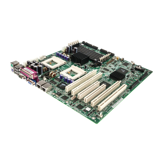
Introduction Introduction This chapter provides an architectural overview of the Intel® SDS2 Server Board. It provides a view of the functional blocks and their electrical relationships. The figure below shows the functional blocks of the Server Board and the plug-in modules that it supports. -
Page 16: Architecture
Standard I/O Server management The SDS2 Server Board provides six DIMM sockets for a maximum memory capacity of 6 GB. Only registered PC-133 compliant Registered SDRAM memory modules are supported. The current tested memory listing is posted on the Intel technical support web site: http://support.intel.com/support/motherboards/server/SDS2/... - Page 17 Intel® Server Board SDS2 Architecture 64-bit, 66-MHz 3.3 V full-length PCI segment C (P64-C) with one embedded device Dual Channel Wide Ultra160 SCSI controller: Adaptec* AIC-7899W Two 64-bit 3.3 V Slots: PCI slots 5 and 6 LPC (Low Pin Count) bus segment with two embedded devices...
-
Page 18: Processor And Chipset
Module Bus (IMB) provides the interface to two 64-bit, 66-MHz Rev 2.2 compliant PCI buses via the CIOB20. The SDS2 DP Server Board directly supports up to 6 GB of ECC memory, using six PC-133- compliant registered SDRAM DIMMs. The ECC implementation in the HE-SL can detect and correct single-bit errors, and it can detect multiple-bit errors. - Page 19 #1 should be populated before processor socket #2. BIO 50 (released on FAB 5) supports the tB1 stepping, CPUID 06B4. These processors are being evaluated for addition to supported processor list. The current Intel support web site has the latest supported processor list for SDS2: http://support.intel.com/support/motherboards/server/SDS2/.
-
Page 20: Processor Voltage Regulator Module (Vrm)
Table 30. BMC Beep Codes lists all of the error codes. Memory Subsystem The SDS2 Server Board supports up to six DIMM sockets for a maximum memory capacity of 6 GB using 1 GB DIMMs. The DIMM organization is x72, which includes 8 ECC check bits. ECC from the DIMMs is passed through to the processor front side bus. -
Page 21: Figure 2. Sds2 Memory Bank Layout
Table 2. Memory DIMM Pairs Memory DIMM DIMM PAIR DIMM1A, DIMM1B 1, 2 DIMM2A, DIMM2B 3, 4 DIMM3A, DIMM3B 5, 6 DIMM Pair 1 DIMM Pair 2 DIMM Pair 3 Figure 2. SDS2 Memory Bank Layout Revision 1.2 Order Number: A85874-002... -
Page 22: C Bus
Processor and Chipset Intel® Server Board SDS2 3.2.2 C Bus An I C* bus is between the BMC and the six DIMM slots. This bus is used by the system BIOS to retrieve DIMM information needed to program the HE-SL memory registers which are required to boot the system. -
Page 23: Cnb20He-Sl Champion North Bridge
P32-A supports the following embedded devices and connectors: CSB5: South Bridge Two Intel® 82550PM 10/100 Fast Ethernet PCI network interface controllers An ATI RAGE XL Video Controller with 3D/2D graphics accelerator Two 32-bit, 33-MHz 5V full length PCI Slots Revision 1.2... -
Page 24: Ciob20 Champion I/O Bridge
Processor and Chipset Intel® Server Board SDS2 3.3.2 CIOB20 Champion I/O Bridge The Champion I/O Bridge (CIOB) is a 352-pin ball-grid array device and provides an integrated I/O bridge that provides a high-performance data flow path between the IMBus and the 64-bit I/O subsystem. -
Page 25: I/O Subsystem
I/O Subsystem PCI Subsystem The primary I/O bus for SDS2 DP Server Board is PCI, with three PCI bus segments. The PCI buses comply with the PCI Local Bus Specification, Rev 2.2. The P32-A bus segment is directed through the HE-SL North Bridge while the two 64bit segments, P64-B and P64-C, are directed through the CIOB20 I/O Bridge. -
Page 26: 64-Bit, 66-Mhz Pci Subsystem
4.1.1.2 P32-A Arbitration P32-A supports seven PCI masters (ATA RAGE XL, two Intel 82550s, PCI masters from slots 3 and 4, CSB5, and HE-SL). All PCI masters must arbitrate for PCI access, using resources supplied by the HE-SL. The following table defines the arbitration connections. -
Page 27: Table 7. P64-B Arbitration Connections
Intel® Server Board SDS2 I/O Subsystem Table 4. P64-B Configuration IDs IDSEL Value Device PCI Slot 1 PCI Slot 2 Table 5. P64-C Configuration IDs IDSEL Value Device Adaptec AIC-7899W SCSI Controller PCI Slot 5 PCI Slot 6 4.1.2.2 P64-B Arbitration P64-B supports three PCI masters (PCI masters from slots 1 and 2, and CIOB). -
Page 28: Ultra160 Scsi
1024 x 768 resolution in 8/16/24/32 bpp modes under 2D and up to 800 x 600 resolution in 8/16/24/32 bpp modes under 3D. It also supports both CRT and LCD monitors at up to 100 Hz vertical refresh rate. The SDS2 Server Board provides a standard 15- pin VGA connector. -
Page 29: Network Interface Controller (Nic)
The SDS2 Server Board supports two 10Base-T / 100Base-TX network subsystem using the Intel 82550-PM NIC. The 82550 components are highly integrated PCI LAN controllers in a thin BGA 15 mm2 package. The controller’s baseline functionality is equivalent to that of the Intel 82559 with the addition of Alert on LAN* functionality. -
Page 30: Nic Connector And Status Leds
PCI bus interface. In the SDS2 Server Board implementation, the primary role of the CSB5’ is to provide the gateway to all PC-compatible I/O devices and features. The SDS2 uses the following CSB5... -
Page 31: Usb Interface
USB connectors. The SDS2 Server Board provides a three external USB connector interface on the rear I/O. One additional USB is supported internally through a 10-pin header (2 X 5) that can be cabled to a front panel board. -
Page 32: Chipset Support Components
General Purpose Input and Output - GPIO The National Semiconductor* PC87417 Super I/O provides number of general-purpose input/output pins that the SDS2 Server Board utilizes. The following table identifies the pin, the signal name used in the schematic and a brief description of its usage. - Page 33 Intel® Server Board SDS2 I/O Subsystem Pin # Signal Name Description N_BMC_SWIN N_BMCPWRN Power LED from BMC N_EXTEN_00 External Event N_SUPERSCI_00 System Control Interrupt used to detect wake-up events N_SIO_CLK_RTC_BMC Real Time Clock output to BMC N_P2_PME Power Management Event from PCI Bus (P64-B segment)
-
Page 34: Intel® Server Board Sds2
Intel® Server Board SDS2 4.6.2 BIOS Flash The SDS2 Server Board incorporates a Fairchild* 29LV008B 8Mbit Flash ROM. The flash device is connected through the X-bus of the CSB5. Interrupt Routing The SDS2 Server Board interrupt architecture implements both PC-compatible PIC mode and APIC mode interrupts through the use of the integrated I/O APICs in the CSB5. -
Page 35: Apic Interrupt Routing
4.7.2 APIC Interrupt Routing For APIC mode, the SDS2 interrupt architecture incorporates three Intel I/O APIC devices to manage and broadcast interrupts to local APICs in each processor. The I/O APICs monitor each interrupt on each PCI device including PCI slots in addition to the ISA compatibility interrupts IRQ (0-15). -
Page 36: Figure 3. Sds2 Interrupt Routing Diagram (Csb5 Internal)
PCIIRQ PCIIRQ to PCIIRQ16 PCI Cycle PCIIRQ17 MAPPING PCIIRQ18 SCAN1 PCIIRQ19 IOAPIC PCIIRQ16- PCIIRQ20 MASK for PCIIRQ31 PCIIRQ21 PCIIRQ16-31 PCIIRQ22 PCIIRQ23 PCIIRQ24 PCIIRQ25 PCIIRQ26 PCIIRQ27 PCIIRQ28 PCIIRQ16 Figure 3. SDS2 Interrupt Routing Diagram (CSB5 Internal) Revision 1.2 Order Number: A85874-002... -
Page 37: Figure 4. Sds2 Interrupt Routing Diagram
PCIIRQ5 Slot2 INTA PCIIRQ6 PIRQ1 Slot3 INTA PCIIRQ7 Slot4 INTA PCIIRQ8 Slot5 INTA PCIIRQ9 Slot6 INTA PCIIRQ10 INTBCD PCIIRQ11 PIRQ_LATCH INTBCD PCIIRQ12 INTBCD PCIIRQ13 PCIIRQ14 SCI from SIO PCIIRQ15 Figure 4. SDS2 Interrupt Routing Diagram Revision 1.2 Order Number: A85874-002... -
Page 38: Figure 5. Sds2 Pci Interrupt Mapping Diagram
PCI IRQ 12 NIC 1 PCI IRQ 2 NIC 2 PCI IRQ 3 VIDEO PCI IRQ 4 PORT A PCI IRQ 0 SCSI PCI IRQ 1 PORT B ZCR Present Figure 5. SDS2 PCI Interrupt Mapping Diagram Revision 1.2 Order Number: A85874-002... -
Page 39: Server Management
Server Management Server Management The SDS2 server management features are implemented using the Sahalee Server Board Management Controller chip. The Sahalee BMC is an ASIC packaged in a 156-pin BGA that contains a 32-bit RISC processor core and associated peripherals. The following diagram illustrates the SDS2 server management architecture. -
Page 40: Figure 6. Sds2 Sahalee Bmc Block Diagram (View As Reference Only)
LVDS-A Term. 3 SMM- Platform BIOS LVDS-B Term. 1 System Management Chip set NMIs LVDS-B Term. 2 Interrupt Routing Chip set SMI LVDS-B Term. 3 Figure 6. SDS2 Sahalee BMC Block Diagram (View as Reference Only) Revision 1.2 Order Number: A85874-002... -
Page 41: Sahalee Baseboard Management Controller
Fan speed measurement channels General-Purpose Logic I/O pins Remote temperature measurement On-chip temperature sensor Chassis intrusion detection The table below details some of the inputs on Hecetas as used in the SDS2. Table 14. ADM1026 Input Definition Signal Name Description N_ADM_DIS_CPU1_L... -
Page 42: Table 15. Temperature Sensors
+/- 5°C or better Secondary Processor Secondary processor socket thermal sensor 8-bit +/- 5°C or better The table below details some of the inputs on Sahalee as used in the SDS2. Table 16. Sahalee Input Definition Signal Name Description N_SLOT1OCC_00... -
Page 43: Fault Resilient Booting
Rear System Fan 2 Speed N_MEM_ALERT_L Memory ECC Error Detect N_BMC_SECUREMODE Secure Mode Detect Note: For a complete listing of BMC sensors, please refer to SDS2 Baseboard Management Controller External Product Specification. ADM1026 Sahalee Figure 7. SDS2 Locations of ADM1026 and Sahalee 5.1.1... -
Page 44: System Reset Control
Intel® Server Board SDS2 System Reset Control Reset circuitry on the SDS2 Server Board looks at resets from the front panel, CSB5, ITP, and processor subsystem to determine proper reset sequencing for all types of reset. The reset logic is designed to accommodate a variety of ways to reset the system, which can be divided into the... -
Page 45: Table 17. Ipmb Bus Devices
3VSB 0xBC Power Unit FRU 3VSB 0xAC Note: The power supply entries in Table 19 apply only to the Intel® SC5100 chassis. Reference chassis power supplies may utilize different addresses. Table 20. Private I C Bus 3 Devices Function Voltage... -
Page 46: Error Reporting
NIC2 3VSB 0x86 Error Reporting This section documents the types of system bus error conditions monitored by the SDS2 Server Board. 5.4.1 Error Sources and Types One of the major requirements of server management is to correctly and consistently handles system errors. -
Page 47: Memory Bus Errors
S5: Soft off. Only the RTC section of the chip set and the BMC are running in this state The SDS2 Server Board supports sleep states s0, s1, s4, and s5. When the Server Board is operating in ACPI mode, the operating system retains control of the system and the operating system policy determines the entry methods and wake up sources for each sleep state. - Page 48 Server Management Intel® Server Board SDS2 Setup Utility (F2) can change the AC link mode settings. Revision 1.2 Order Number: A85874-002...
-
Page 49: Bios
Intel® Server Board SDS2 BIOS BIOS This section describes the BIOS-embedded software for the SDS2 server board. The BIOS contains standard PC-compatible basic input/output (I/O) services, system-specific hardware configuration routines and register default settings that are embedded in Flash read-only memory (ROM). -
Page 50: Bios Error Handling
Resource allocation support BIOS Error Handling This section defines how errors are handled by the system BIOS on the SDS2 server board. Also discussed are the role of BIOS in error handling, and the interaction between the BIOS, platform hardware, and server management firmware with regard to error handling. In addition, error-logging techniques are described and beep codes for errors are defined. -
Page 51: Table 22. Bios Generated Sel Errors
Intel® Server Board SDS2 BIOS The BIOS logs the following SEL entries. Table 22. BIOS Generated SEL Errors Sensor Sensor Sensor- Sensor Type Number Type Specific Event Code Offset Processor FRB1/BIST Failure FRB2/Hang in POST Failure Memory Uncorrectable ECC POST Memory –... -
Page 52: Smi Handler
BIOS Intel® Server Board SDS2 Table 23: Event Request Message Event Data Field Contents Event Event Data Trigger Class Discrete 00 = Unspecified byte 2 01 = Previous state and/or severity in byte 2 10 = OEM code in byte 2... -
Page 53: Firmware (Bmc)
Post Error code is disabled in the BIOS Setup in the Advanced menu. Sensor Name, Sensor number and Sensor type for the SDS2 platform are listed in the following Table 24 Platform SEL Log Sensors for SDS2. - Page 54 BIOS Intel® Server Board SDS2 Event/ Event Sensor Reading Offset Sensor Type Name Type Triggers Power Off, Power Unit Power Unit - Sensor Power Cycle, Status Specific - 6Fh A/C Lost, Redundancy Regain Power Unit Power Unit - Generic 0Bh...
- Page 55 Intel® Server Board SDS2 BIOS Event/ Event Sensor Reading Offset Sensor Type Name Type Triggers Threshold - BB -12V Voltage – 02h Threshold - BB V Voltage – 02h Threshold - Proc VRM1 Voltage – 02h Threshold - Proc VRM2 Voltage –...
- Page 56 BIOS Intel® Server Board SDS2 Event/ Event Sensor Reading Offset Sensor Type Name Type Triggers Fan Boost Threshold - Front Panel OEM - C7h Temp Fan Boost Threshold - OEM - C7h PDB Temp Fan Boost Threshold - Proc 1 Core...
- Page 57 Intel® Server Board SDS2 BIOS Event/ Event Sensor Reading Offset Sensor Type Name Type Triggers Presence, Power Power Supply - Sensor Failure, Supply 2 Specific - 6Fh Predictive Fail, A/C Lost Presence, Power Power Supply - Sensor Failure, Supply 3...
- Page 58 BIOS Intel® Server Board SDS2 Event/ Event Sensor Reading Offset Sensor Type Name Type Triggers Fault Status Asserted, Slot Connector Sensor DIMM 6 - 21h Specific - 6Fh Device Installed, Disabled S0 / G0, System ACPI System ACPI Sensor Power State –...
-
Page 59: Error Messages And Error Codes
Intel® Server Board SDS2 BIOS 6.2.5 Error Messages and Error Codes The system BIOS displays error messages on the video screen. Before video initialization, beep codes inform the user of errors. POST error codes are logged in the System Event Log. The BIOS displays POST error codes on the video monitor. -
Page 60: Table 27. Standard Bios Post Codes
BIOS Intel® Server Board SDS2 The following table contains the POST codes displayed during the boot process. A beep code is a series of individual beeps on the PC speaker, each of equal length. The following table describes the error conditions associated with each beep code and the corresponding POST checks point code as seen by a ‘port 80h’... - Page 61 Intel® Server Board SDS2 BIOS Beeps Reason Reset Programmable Interrupt Controller 1-3-1-1 Test DRAM refresh 1-3-1-3 Test 8742 Keyboard Controller Set ES segment register to 4GB 1-3-3-1 Auto size DRAM, system BIOS stops execution here if the BIOS does not detect any usable...
- Page 62 BIOS Intel® Server Board SDS2 Beeps Reason Initialize the POST display service Display prompt “Press F2 to enter SETUP” Disable L1 cache during POST Test RAM between 512 and 640k Test extended memory Test extended memory address lines Jump to UserPatch1...
-
Page 63: Table 28. Recovery Bios Post Codes
Intel® Server Board SDS2 BIOS Beeps Reason Fix up Multi Processor table Search for option ROMs. One long, two short beeps on checksum failure Check for SMART Drive Shadow option ROMs Set up Power Management Initialize security engine Enable hardware interrupts... -
Page 64: Table 29. Post Error Messages And Codes
BIOS Intel® Server Board SDS2 6.2.5.3 POST Error Codes and Messages The following table defines POST error codes and their associated messages. The BIOS prompts the user to press a key in case of serious errors. Some error messages are preceded by the string "Error”... -
Page 65: Table 30. Bmc Beep Codes
Intel® Server Board SDS2 BIOS Code Error Message Failure Description 0614 COM A config. error - device disabled 0615 COM B configuration changed 0616 COM B config. error - device disabled 0617 Floppy configuration changed 0618 Floppy config. error - device disabled... -
Page 66: Setup Utility
BIOS Intel® Server Board SDS2 Code Reason for Beep 1-5-1-1 FRB failure (processor failure) 1-5-2-1 Empty Processor 1-5-2-2 No Processor 1-5-2-3 Processor configuration error (e.g., mismatched VIDs) 1-5-4-2 Power fault: DC power unexpectedly lost (power control failures) 1-5-4-3 Chipset control failure... - Page 67 Intel® Server Board SDS2 BIOS Options Menu Each Option Menu occupies the left and center sections of the screen. Each menu contains a set of features. Selecting certain features within a major Option Menu drops you into submenus. Item Specific Help Screen An item-specific help screen is located at the right side of the screen.
- Page 68 BIOS Intel® Server Board SDS2 Option Description Help Pressing F1 on any menu invokes the g eneral Help window. This window describes the Setup key legend. The up arrow, down arrow, Page Up, Page Down, Home, and End keys scroll the text in this window.
-
Page 69: Table 32. Main Menu Selections
Intel® Server Board SDS2 BIOS 6.3.2.3 Menu Selection Bar The Menu Selection Bar is located at the top of the screen. It displays the various major menu selections available to the user: Main Menu. Advanced Menu. Security Menu. Server Menu. -
Page 70: Table 33. Primary Master And Slave Ide Submenu Selections
BIOS Intel® Server Board SDS2 Feature Option Description Spanish Italian French German Table 33. Primary Master and Slave IDE Submenu Selections Feature Option Description Type Auto Select the byte of device that is attached to the IDE. Channel. None If User is selected, the user will need to enter the... -
Page 71: Table 34. Processor Settings Submenu Selections
Intel® Server Board SDS2 BIOS Feature Option Description Transfer Mode Standard Select the method for moving data to/from the drive. FPIO 1 This field is informational only, for Type Auto. FPIO 2 This field is updated to display only the modes supported by the attached device. -
Page 72: Table 35. Advanced Menu Selections
BIOS Intel® Server Board SDS2 6.3.2.3.2 Advanced Menu Selections The following tables describe the menu options and associated submenus available on the Advanced Menu. Please note that MPS 1.4/1.1 selection is no longer configurable. The BIOS always builds MPS 1.4 tables. -
Page 73: Table 37. Pci Configuration Menu Selections
Intel® Server Board SDS2 BIOS Disabled Extended RAM Step Selects the size of step to use during Extended RAM tests. 1 MB 1 KB Every- Location Table 37. PCI Configuration Menu Selections Feature Option Description Embedded SCSI Selects sub-menu Embedded NIC 1... - Page 74 BIOS Intel® Server Board SDS2 Feature Option Description Option ROM Scan Enabled Enable option ROM scan of the selected device. Disabled Revision 1.2 Order Number: A85874-002...
-
Page 75: Table 41. I/O Device/Peripheral Configuration Submenu Selections
Intel® Server Board SDS2 BIOS Table 41. I/O Device/Peripheral Configuration Submenu Selections Feature Option Description Serial Port 1 Disabled If set to “Auto,” BIOS or OS configures the port. Enabled Auto Base I/O Address 3F8h Selects the base I/O address for COM port 1. -
Page 76: Table 42. Advanced Chipset Controller Submenu Selections
BIOS Intel® Server Board SDS2 Table 42. Advanced Chipset Controller Submenu Selections Feature Option Description PCI Device Selects sub-menu Wake On Ring Enabled Only controls legacy wake up. May not be present if not supported. Disabled Wake On LAN Enabled Only controls legacy wake up. -
Page 77: Table 45. Server Menu Selections
Intel® Server Board SDS2 BIOS Feature Option Description Set Administrative Press Enter When the Enter key is pressed, the user is prompted Password for a password; press ESC key to abort. Once set, can be disabled by setting to a null string, or clear password jumper on board. -
Page 78: Table 46. System Management Submenu Selections
BIOS Intel® Server Board SDS2 Feature Option Description Assert NMI on PERR Disabled If enabled, PCI bus parity error (PERR) is enabled and is routed to NMI. Enabled Assert NMI on SERR Enabled If enabled, PCI bus system error (SERR) is enabled and is routed to NMI. -
Page 79: Table 47. Console Redirection Submenu Selections
Intel® Server Board SDS2 BIOS Table 47. Console Redirection Submenu Selections Feature Option Description Serial Port Address Disabled When enabled, Console Redirection uses the I/O port specified. Choosing “Disabled” completely disables On-board COM A Console Redirection. On-board COM B Baud Rate... -
Page 80: Table 49. Hard Drive Selections
BIOS Intel® Server Board SDS2 Table 49. Hard Drive Selections Option Description Drive #1 (or actual drive To select the boot drive, use the up and down arrows to highlight a device, string) then press the plus key (+) to move it to the top of the list or the minus key (–) to move it down. -
Page 81: Cmos Memory Definition
Intel® Server Board SDS2 BIOS 6.3.3 CMOS Memory Definition The CMOS map is available in the NVRAM.LST file generated for every BIOS release. The CMOS map is subject to change without notice. 6.3.4 Clearing CMOS The BIOS detects the state of the CMOS jumper. If the jumper is set to “CMOS Clear” prior to power-on or a hard reset, the BIOS changes the CMOS and NVRAM settings to a default state. -
Page 82: User Binary Area
6.4.5 Recovery Mode The SDS2 baseboard supports a method for performing a BIOS recovery in order to restore the system from a failed flash. This utilizes a jumper on the baseboard. The system beeps through out the process. The recovery BIOS boots only from a 1.44 MB floppy diskette inserted into a 1.44 MB floppy drive or LS-120/240 drive. - Page 83 Intel® Server Board SDS2 BIOS 5. Turn on system power. The system boots from the recovery diskette. The BIOS will beep twice when the update process starts. The system will continue to beep while updating the BIOS. If BIOS update completes successfully, the system will stop beeping.
-
Page 84: Clock/Voltage Generation And Distribution
Intel® Server Board SDS2 Clock/Voltage Generation and Distribution Clock All buses on the SDS2 Server Board operate using synchronous clocks. Clock synthesizer/driver circuitry on the Server Board generates clock frequencies and voltage levels as required, including the following: 133 MHz at 2.5 V logic levels: For CPU1, CPU2, HE-SL, DIMM Sockets and the ITP port 66 MHz at 3.3 V logic levels: For HE-SL, CIOB, P64-B and P64-C PCI slots... -
Page 85: Figure 8. Sds2 Server Board Clock Generation/Distribution Diagram
Intel® Server Board SDS2 Clock/Voltage Generation and Distribution Figure 8. SDS2 Server Board Clock Generation/Distribution Diagram Revision 1.2 Order Number: A85874-002... -
Page 86: Voltage
Server Board are used to create the following voltages: +3.3VSB VCORE for the CPUs VTT for the CPUs +2.5V for the chipsets +1.8V for the onboard SCSI The following figure illustrates voltage generation and distribution on the SDS2 Server Board. Revision 1.2 Order Number: A85874-002... -
Page 87: Figure 9. Sds2 Server Board Voltage Generation/Distribution Diagram
Intel® Server Board SDS2 Clock/Voltage Generation and Distribution Figure 9. SDS2 Server Board Voltage Generation/Distribution Diagram Revision 1.2 Order Number: A85874-002... -
Page 88: Connections
Yellow COM_CPU Black +12V_CPU Yellow Note: The SDS2 server board requires a +12 V Power Connector. The board will not power on without +12 V Power supplied to this connector. Table 54. Aux Signal Connector Pin-out Signal Name I2C Clock I2C Data Revision 1.2... -
Page 89: Memory Module Connector
ReturnS 3.3RS Memory Module Connector The SDS2 Server Board has six PC-133 SDRAM DIMM connectors and supports registered SDRAM modules. For more information on DIMM modules refer to PC SDRAM Registered DIMM Design Support Document Rev 1.2. Table 55. DIMM Connector Pin-out... -
Page 90: System Management Headers
5 VSB Clock Line 8.3.3 SCSI HSBP (IPMB) Connector The Intelligent Platform Management Bus (IPMB), as used on SDS2 Server Board allows for connections to Hot Swap Back planes (HSBP) with multiple hard drives. Table 58. HSBP-A Connector Pin-out Signal Name... -
Page 91: Front Panel Header
Intel® Server Board SDS2 Connections Table 59. HSBP-B Connector Pin-out Signal Name Description IPMB_SDA 5 VSB Data Line IPMB_SCL 5 VSB Clock Line I2C_ADR_CNTRL Address Control Front Panel Header A 34-pin header is provided for cabling to the system front panel. The header contains reset, NMI, power control buttons, and LED indicators. -
Page 92: Pci Slot Connector
Connections Intel® Server Board SDS2 PCI Slot Connector The Server Board support two 32-bit, 33-MHz 5V PCI Slots and four 64-bit, 66-MHz 3.3 V PCI Slots. The tables below define their pin-outs. Table 61. 32-bit 5 V PCI Slot Pin-out... - Page 93 Intel® Server Board SDS2 Connections Side B Side A Side B Side A -12 V TRST# M66EN AD[09] +12 V Ground Ground Ground Ground Ground AD[08] C/BE[0]# +5 V +5 V AD[07] +3.3 V +5 V INTA# +3.3 V AD[06]...
-
Page 94: I/O Connectors
HSYNC (horizontal sync) VSYNC (vertical sync) DDCCLK 8.6.2 SCSI Connector The SDS2 Server Board provides two SCSI connectors accessible internally. The following table details the pin-out of the 68-pin SCSI connector. Table 64. 68-pin SCSI Connector Pin-out Connector Contact Number Signal Name... -
Page 95: Nic Connectors
+DB(9) -DB(9) +DB(10) -DB(10) +DB(11) -DB(11) 8.6.3 NIC Connectors The SDS2 Server Board supports two RJ-45 connectors. The following table details the pin-out of these connectors. Table 65. RJ-45 Connector Pin-out Signal Name Signal Name Revision 1.2 Order Number: A85874-002... -
Page 96: Ide Connector
Connections Intel® Server Board SDS2 TXDP RXDP TXDM RXDM Activity LED Cathode Link LED Anode Speed LED Anode 3VSB 8.6.4 IDE Connector There is one IDE channel on the Server Board through the use of a 40-pin connector. The connector pin-out is detailed in the table below. Note IDE LED hard disk drive activity (Pin 39) signal is not routed to the front panel connector. -
Page 97: Floppy Connector
Intel® Server Board SDS2 Connections Signal Name Fused 5 V USB_PORT1_D- USB_PORT1_D+ Fused 5 V USB_PORT2_D- USB_PORT2_D+ Fused 5 V USB_PORT3_D- USB_PORT3_D+ A 10-pin header (2X5) located at CN18 on the Server Board provides an option to cable out the USB to the front panel. -
Page 98: Serial Port Connector
Connections Intel® Server Board SDS2 Table 69. 34-pin Floppy Connector Pin-out Signal Name Signal Name FD_DENSEL Test Point FD_DRATE0 FD_INDEX_L FD_MTRA_L FD_DRVSELB_L FD_DRVSELA_L FD_MTRB_L FD_DIR_L FD_STEP_L FD_WDATA_L FD_WGATE_L FD_TRK0_L FD_WPT_L FD_RDATA_L FD_HDSEL_L FD_DSKCHG_L 8.6.7 Serial Port Connector Two serial ports are provided on the Server Board, one DB9 connector is located on the rear I/O to supply COM1 and a 10-pin header at location CN33 provides COM2. -
Page 99: Parallel Port
Intel® Server Board SDS2 Connections Signal Name Description Data Carrier Detect Receive Data Transmit Data Data Terminal Ready Ground Data Set Ready Request to Send Clear to Send Ring Indicate 8.6.8 Parallel Port One DB25 parallel port connector is provided on the rear I/O. The following table details the pin- out of the connector. -
Page 100: Miscellaneous Headers
RAID controller cards to connect their disk activity cables to the front panel hard disk LED activity light. Note that IDE hard disk activity LED is not enabled on the SDS2 board via the front panel connector at CN37. Pins 2 and 3 are tied together routed through an AND gate to Pin 9 of CN37 front panel connector. -
Page 101: Rear I/O Panel
The following diagram shows the locations of keyboard, mouse, USB, serial, parallel, video, and NIC connector interfaces on the system I/O panel, as viewed from the rear of the system. Figure 10. SDS2 Server Board Rear I/O Panel Connector Manufacturers and Part Numbers The following table shows the quantity and manufacturer’s part numbers for connectors on the... - Page 102 Jumpers Intel® Server Board SDS2 CN Numbers Manufacturer Mfg. Part # Functional Description FOXCONN MH11061-PD2 25-pin DSUB parallel port connector FOXCONN DT10121-P5T DB9 serial port connector FOXCONN HL07051-P5 10-pin serial port header FOXCONN UB1112C-M1 3-pole USB connector FOXCONN HL07051-P9 10-pin USB header...
-
Page 103: Figure 11. Sds2 Configuration Jumpers
OPEN = Protects BMC boot block OPEN CLOSED = RSV Figure 11. SDS2 Configuration Jumpers Note: CN59 CPU Frequency Select jumper header pins are not installed on production FAB4 (PBA A58285-402 or –403) and FAB5 (PBA A58285-502) The following figure details the locations of these jumpers. -
Page 104: Figure 12. Sds2 Configuration Jumper Locations
CPU Frequency Select CPU Frequency Select CPU Frequency Select CN42 FUNCTION FUNCTION CMOS Clear CN46 BIOS Write Protect Password Disable CN47 BMC Write Protect CN48 FRB3 CN49 BIOS Recovery Spare Jumper Figure 12. SDS2 Configuration Jumper Locations Revision 1.2 Order Number: A85874-002... -
Page 105: Table 78. System Configuration Jumper Options
Intel® Server Board SDS2 Jumpers The following tables describe each jumper options. Table 78. System Configuration Jumper Options Option Description CMOS When CN42’s pins 1 and 2 are OPEN (default), CMOS contents are preserved through the system Clear reset. When they are CLOSED, CMOS contents are set to manufacturing default during system reset. -
Page 106: Jumpers
In the event of BIOS corruption, the following procedure may be used to perform a BIOS Recovery boot. 1. Prepare a bootable floppy diskette containing the BIOS recovery files for the SDS2 Server Board obtained from Intel’s web sites. Revision 1.2... -
Page 107: Performing Bmc Force Update
Firmware. 1. Prepare a bootable floppy diskette containing the updated BMC firmware files for the SDS2 Server Board obtained from Intel’s web sites. 2. Power off the system, unplug the power cord, and remove the chassis panel. 3. Add a jumper on CN49 pins 1-2 (BMC Force Update). -
Page 108: 10. Electrical And Thermal Specifications
10.2 Power Consumption The following table shows the power consumed on each supply line for a SDS2 Server Board configured with the following manner. Two processors, each with 30 W max Four DIMMs total, two active (burst) and two standby Three PCI cards, two on 3.3 V and one on 5V... -
Page 109: 10.3 Power Supply Specification
152.4 W 2.4 W 6.0 W 267.0W 10.3 Power Supply Specification This section provides power supply design guidelines for an SDS2-based system; including voltage and current specifications, and power supply on/off sequencing characteristics. Table 83: SDS2 Power Supply Specification Output Units Tolerance 3.3 V... - Page 110 Electrical and Thermal Specifications Intel® Server Board SDS2 Revision 1.2 Order Number: A85874-002...
-
Page 111: 10.4 Estimateded Server Board Mtbf
The estimated Mean-Time Between Failures (MTBF) is calculated at 103,996 hours at a maximum operating temperature Figure 13. Output Voltage Timing The table below shows the calculated numbers. Table 87. Estimated SDS2 Server Board MTBF Table 85: Turn On/Off Timing Item... -
Page 112: 11. Mechanical Specifications
Intel® Server Board SDS2 Mechanical Specifications 11. Mechanical Specifications The following figure shows the Server Board mechanical drawing. Figure 15. SDS2 Server Board Mechanical Drawing Revision 1.2 Order Number: A85874-002... -
Page 113: 12. Regulatory And Integration Information
Compliance to EU Low Voltage Directive via EN60 950 / IEC 60950 The SDS2 server board has been tested and verified to comply with the following EMC regulations when installed in a compatible Intel host system. For information on Intel compatible host system(s), refer to Intel’s Server Builder website, or contact your local Intel representative. -
Page 114: 12.2 Installation Instructions
Intel® Server Board SDS2 Regulatory and Integration Information UL Recognition Mark (USA/Canada) CE Mark (Europe) C-Tick Mark (Australia) GOST Mark (Russia) BSMI Mark (Taiwan) 12.2 Installation Instructions CAUTION: Follow these guidelines to meet safety and regulatory requirements when installing this board assembly. -
Page 115: Ensure Host Computer And Accessory Module Certifications
Regulatory and Integration Information Intel® Server Board SDS2 If the host chassis, power supply, and other modules have not passed applicable EMC certification testing before integration, EMC testing must be conducted on a representative sample of the newly completed computer. -
Page 116: Use Only For Intended Applications
Intel® Server Board SDS2 Regulatory and Integration Information 12.2.5 Use Only for Intended Applications This product was evaluated for use in ITE computers that will be installed in offices, schools, computer rooms and similar locations. The suitability of this product for other product categories other than ITE applications (such as medical, industrial, alarm systems, and test equipment) may require further evaluation. -
Page 117: 13. Errata Listing
The following tables indicate the errata and the document changes that apply to the Intel® Server Board SDS2. Intel intends to fix some of the errata in a future stepping of components, and to account for the other outstanding issues through documentation or specification changes as noted. - Page 118 32-bit PCI bus controlled by the HE-SL north bridge No Fix SDS2 PCI slot current levels supported by the 5V rail No Fix OB P100 NICs do not show at POST but attempt PXE boot and appear in Boot Menu None Following are in-depth descriptions of each erratum change indicated in the tables above.
-
Page 119: 13.2 Errata
BIOS updates to be performed from a PXE server or from a network drive. Implication: The Intel Server Board SDS2 BIOS cannot be updated from a PXE server or a network drive. The BIOS update must be performed from a floppy diskette or from a hard drive. -
Page 120: First Characters And Arrow Keys Not Echoed With Console Redirection
Make sure that console redirection is set to disabled in BIOS Setup (this is the default BIOS setting) before performing a FRU/SDR file update. Status: Fixed. This issue is fixed in SDS2 BIOS Production Release 2.1 (Build 44) and later versions. First characters and arrow keys not echoed with console... -
Page 121: Intel® Server Board Sds2 Cd-Rom Issues
Intel Server Board SDS2 BIOS Logo screen is enabled. Workaround: A workaround for this issue is to press the ESC key when the Intel BIOS logo screen appears. Alternately, the Intel BIOS logo screen may be disabled. To disable the Intel BIOS logo screen, access the Intel Server Board SDS2 BIOS Setup (by pressing F2 when the Intel BIOS logo screen appears). -
Page 122: Nic Driver Set 5.12 V.2.3.15 For Unixware* 7.1.1 Drops Dpc Lan Connection
Problem: When the NIC driver set 5.1.2 v.2.3.15 for UnixWare* 7.1.1 is utilized on the Intel® Server Board SDS2, the DPC LAN connection to the SDS2 server is dropped when a power control action is initiated. Implication: NIC driver set 5.1.2 v.2.3.15 for UnixWare* 7.1.1 should not be used with the Intel®... -
Page 123: Extended Ram Step Disable Option In Bios Setup Has No Effect
“Disabled” in BIOS Setup. Workaround: None. Status: Fixed. This issue is fixed in SDS2 BIOS Production Release 2.1 (Build 44) and later versions. High resolution video modes do not work correctly Problem: Several of the high resolution video modes listed as supported in Table 6 of the Intel®... -
Page 124: Lower Performance With Cas Latency 2 Memory
Status: Fixed. This issue is fixed in SDS2 BIOS Production Release 2.4 (Build 47) and later versions. When using SDS2 BIOS Production Release 2.4 (Build 47), the copy bandwidth observed with CAS Latency 2 memory installed is greater than the copy bandwidth with CAS Latency 3 memory installed. -
Page 125: Novell Netware* V. 6.0 Does Not Install On Sds2
Errata Listing Intel® Server Board SDS2 Implication: The SDS2 server board will not complete POST if more than 4GB or more of total system memory is installed and the Extended RAM step option in BIOS Setup is set to “Every Location”. -
Page 126: Sds2 Build Your Own (Byo) Platform Confidence Test (Pct) V. 1.00 Fails On The First Run
SDS2 Build Your Own (BYO) Platform Confidence Test (PCT) v. 1.00 fails on the first run Problem: The first time the SDS2 BYO PCT v. 1.00 is run on an SDS2 system following a cold boot, the following error message will be encountered: ***ERROR BMC.CHECKCHASSISSTATUS V4.11.1.0107 Chassis Status miscompared with known values. -
Page 127: Sds2 0B75: System Voltage Out Of The Range Post Message
Status: NoFix. Disconnecting and reconnecting the SC5100 front panel cable from the SDS2 server board while 5V standby voltage is applied to the system is not a supported action. This action causes the SC5100 front panel temperature sensor to report an invalid temperature reading. Customers must disconnect the AC power cord from the SDS2/SC5100 system before disconnecting or reconnecting the SC5100 front panel cable to the server board. -
Page 128: Sds2 Board Level Operating Temperature And Power Supply Voltage Tolerance Modification
(TPS) Rev. 1.0, the board level operating temperature is specified as 0 C to 55 C. In Table 75 of the SDS2 TPS Rev. 1.0, the power supply tolerance is specified as 5% for the 3.3V rail. Intel has induced a failure condition during board level temperature and voltage margin testing at 55 C and 5% voltage on the 3.3V rail in SDS2 Server Boards configured with PCI adapters in the... - Page 129 Intel® Server Board SDS2 Implication: If you are installing the Intel Server Board SDS2 into the Intel SC5100 Server Chassis, Intel recommends installing the rubber bumper included with the server board. If you are installing the Intel Server Board SDS2 into a chassis other than the Intel SC5100 Server Chassis, compare the rubber bumper height to the chassi standoff height.
-
Page 130: Keyboard And Mouse Do Not Function Under Microsoft* Windows* 2000 When Legacy Usb Is Enabled In Bios Setup
Leave the Legacy USB Support option in BIOS setup set to “Disabled”, which is a default option, if Microsoft* Windows* 2000 is being used. Status: Fix. Intel has identified a fix for this issue, which will be incorporated in the SDS2 FAB 5 server board. Revision 1.2... -
Page 131: Data Miscompares When Using Seagate* Ata Iii Model St310215A Hard Drives
Boot to service partition via modem fails Problem: When utilizing the direct platform control (DPC) feature of Intel Server Control (ISC) v. 3.5.2 software to boot a SDS2 server board to the service partition via modem, the server board will hang during ROM-DOS load. Implication: The DPC feature of ISC v. -
Page 132: Bootable Cd Will Not Boot If Inserted During Option Rom Scan
Intel® Server Board SDS2 Errata Listing Problem: Mechanical interference between the Myelex installed memory module (DIMM) and the onboard SCSI connector occurs if a Wide or Singled Ended SCSI cable is installed on embedded SCSI A or B connector. LVD SCSI cable connectors do not interfer. -
Page 133: Ob P100 Nics Do Not Show At Post But Attempt Pxe Boot And Appear In Boot Menu122
Errata Listing Intel® Server Board SDS2 OB P100 NICs do not show at POST but attempt PXE boot and appear in Boot Menu Problem: On board NIC are not displayed during post but do appear in Boot Device menu. These controllers will also attempt to do a PXE boot if no other bootable devices... -
Page 134: Can Not Change Bios Setup Ide Options Using
Intel® Server Board SDS2 Errata Listing Status: Will Not Fix. Can Not Change BIOS SETUP IDE Options Using <Enter> Key Problem: In SETUP, when attempting to change any option under the Primary/Secondary IDE controller sub-menu, one must use the space bar. The enter key does not function.Key -
Page 135: Com* 3C980C-Tx Nic Causes Microsoft* Windows* 2000 Blue Screen When Greater Than 4Gb Of System Memory Is Installed
4GB of system memory is installed in the SDS2 system. Implication: Blue screens may be encountered under Microsoft* Windows* 2000 when using a 3COM* 3C980C-TX NIC in an SDS2 system with greater than 4GB of system memory installed. Workaround: This issue results because the 3COM 3C980C-TX NIC does not physically support dual address cycles (DAC), therefore, the NIC is not able to access physical addresses above 4GB. -
Page 136: Peer-To-Peer Pci Transactions Are Not Supported Between The Ciob-Controlled 64-Bit Pci Bus And The Legacy 32-Bit Pci Bus Controlled By The He-Sl North Bridge
5V rail to the six PCI slots on the server board. Implication: The SDS2 server board can support a maximum total of 21 amps on the 5V rail to the six PCI slots on the server board. Integrators must consider this when selecting PCI card configurations for use in the SDS2 server board. - Page 137 Errata Listing Intel® Server Board SDS2 therefore does not display any text messages and does not allowing the CTRL- S option. Status: Will not fix. Revision 1.2 Order Number: A85874-002...
-
Page 138: Glossary
Intel® Server Board SDS2 Glossary Glossary This appendix contains important terms used in the preceding chapters. For ease of use, numeric entries are listed first (e.g., “82460GX”) with alpha entries following (e.g., “AGP 4x”). Acronyms are then entered in their respective place, with non-acronyms following. - Page 139 Glossary Intel® Server Board SDS2 Term Definition multiplexor Non-maskable Interrupt Original equipment manufacturer Unit of electrical resistance P32-A 32 bit PCI Segment P64-B Full Length 64/66 MHz PCI Segment P64-C Full Length 64/66 MHz PCI Segment PBGA Pin Ball Grid Array...
-
Page 140: Reference Documents
ATI RAGE XL Graphics Controller Specifications, Technical Reference Manual, Rev 2.01 VRM 8.5 DC-DC Converter Specification Intel 82550 Fast Ethernet PCI Controller Datasheet Intelligent Platform Management Interface (IPMI) Specification SDS2 Baseboard Management Controller External Product Specification Rev 0.81, Ref. NO. 10282 Revision 1.2 Order Number: A85874-002... -
Page 141: Index
Index Intel® Server Board SDS2 Index 1.25V, 39 Baseboard Temp, 40 12V, 39 Beep Codes, 6, 35, 45, 50 -12V, 39 Beep Codes, 44 BIOS, 45, 46, 47, 48 BIOS components, 34 BIOS defined, 34 2.5 V logic levels, 68 BIOS features, 34 2.5V, 39... - Page 142 Index Intel® Server Board SDS2 Graphics Controller, 2 Data channels, 21 Data transfer, 8 Hard reset, 30 Device ID, 11, 12 Hecetas, 27 DIMM, 42 HE-SL CNB20 North Bridge, 2 DIMM sockets, 2, 6 HE-SL memory registers, 8 DMA Mode, 17...
- Page 143 Intel® Server Board SDS2 Index Memory configuration requirements, 6 Plug-N-Play Auto-configuration Manager, 51 Memory controller, 2, 4, 6, 8 Port-80h card, 44 Memory interleaving, 6 POST, 45 Memory scrubbing, 6, 9 POST codes, 44 MIRQ#, 32 POST Error, 39 Missing CPU Module, 41...
- Page 144 Index Intel® Server Board SDS2 SCSI Controller, 13, 68 Temperature measurement, 27 SDRAM DIMM connectors, 73 Termination voltage, 14, 27 Security, 51, 54 Terminator module, 5 Processor, 45, 46 Timing requirements, 93 SEL Log Sensors, 38 Sensor Event, 37 Sensor Failure, 43...
- Page 145 Intel® Server Board SDS2 Index Zero-channel RAID controller, 14 Revision 1.2 Order Number: A85874-002...