Intel S2600CP Service Manual
Hide thumbs
Also See for S2600CP:
- Technical product specification (223 pages) ,
- Manual (141 pages) ,
- Service manual (189 pages)

Related Manuals for Intel S2600CP


Summary of Contents for Intel S2600CP
- Page 1 ® Intel Server Board S2600CP ® Intel Server System P4000CP Family Service Guide ® A Guide for Technically Qualified Assemblers of Intel identified Subassemblies/Products Order Number: G54899-001...
- Page 2 Intel product could create a situation where personal injury or death may occur. Intel may make changes to specifications and product descriptions at any time, without notice.
-
Page 3: Safety Information
Instrucciones de seguridad importantes Lea todas las declaraciones de seguridad y precaución de este documento antes de realizar cualquiera de las instrucciones. Vea Intel Server Boards and Server Chassis Safety Information en ® el Intel Server Deployment Toolkit 3.0 CD y/o en http://www.intel.com/support/motherboards/server/sb/cs-010770.htm. - Page 4 Take care to grip with, but not squeeze, the pliers or other tool you use to remove a jumper, or you may bend or break the pins on the board. ® ® Intel Server Board S2600CP Intel Server System P4000CP Family Service Guide...
-
Page 5: Preface
® and instructions on how to add and replace components on the Intel Server Chassis P4000M family. For the latest version of this manual, refer to http://www.intel.com/p/en_US/support. - Page 6 See the section on the web page titled, “Document and Guides”. ® If you just received this product and need Intel Server Board S2600CP Quick Start User Guide to install it. ® Intel Server System P4000CP Family Quick Installation User Guide ®...
-
Page 7: Table Of Contents
Installing a PCI Add-in Card ...................... 31 Removing a PCI Add-in Card..................... 33 Design A GPGPU Card Extender ......................34 Installing and Removing an Optical Drive ................... 35 Installing an Optical Drive......................35 ® ® Intel Server Board S2600CP Intel Server System P4000CP Family Service Guide... - Page 8 Table of Contents Removing an Optical Drive ......................36 ® Installing and Removing the Intel RAID C600 Upgrade Key ............37 ® Installing the Intel RAID C600 Upgrade Key ................37 ® Removing the Intel RAID C600 Upgrade Key ................. 37 ®...
- Page 9 Appendix B: Regulatory and Compliance Information ..............162 Appendix C: LED Decoder ........................163 Appendix D: Getting Help ........................168 Warranty Information ....................... 168 ® Appendix E: Intel Server Issue Report Form ..................169 ® ® Intel Server Board S2600CP Intel Server System P4000CP Family Service Guide...
- Page 10 Figure 14. 8 x 2.5 backplane - Rear View ....................12 l® Figure 15. Internal Inte RAID Expander Cards Components ..............12 ® Figure 16. Cable connections for Intel Server System P4308CP4MHEN ..........15 ® Figure 17. Cable routing for Intel Server System P4308CP4MHEN ............16 ®...
- Page 11 Figure 55. Installing an Optical Drive ......................36 Figure 56. Remove an Optical Drive ......................36 Figure 57. Install optical drive filler......................37 ® Figure 58. Installing the Intel RAID C600 Upgrade Key ................. 37 ® Figure 59. Removing the Intel RAID C600 Upgrade Key ................
- Page 12 Figure 144. Boot Manager Screen ......................157 Figure 145. Error Manager Screen ......................157 Figure 146. Exit Screen ..........................158 Figure 147. Diagnostic LED Placement Diagram..................163 ® ® Intel Server Board S2600CP Intel Server System P4000CP Family Service Guide...
- Page 13 ..................160 Table 9. Over Current Protection ......................160 Table 10. System Environmental Limits Summary .................. 160 Table 11. POST Progress Code LED Example ..................164 ® ® Intel Server Board S2600CP Intel Server System P4000CP Family Service Guide xiii...
-
Page 15: Server System Features
O. 8x3.5” Hot-swap HDD Cage ® Intel RAID C600 Upgrade Key Q. PCI-e Retainer ® Figure 1. Intel Server System P4308CP4MHEN View NOTE: Airduct is not shown ® ® Intel Server Board S2600CP Intel Server System P4000CP Family Service Guide... -
Page 16: Intel ® Server System P4308Cp4Mhgc View
O. 8x3.5” Hot-swap HDD Cage ® Intel RAID C600 Upgrade Key Q. PCI-e Retainer ® Figure 2. Intel Server System P4308CP4MHGC View NOTE: Airduct is not shown. ® ® Intel Server Board S2600CP Intel Server System P4000CP Family Service Guide... -
Page 17: Intel ® Server System P4208Cp4Mhgc View
NOTE: Airduct is not shown. Hot Swap Hard Drive Bay and Front Panel Options ® The figure below shows the 8x3.5” drive bay for Intel Server System P4308CP4MHEN and ® P4308CP4MHGC, and 8x2.5” drive bay for Intel Server System P4208CP4MHGC. -
Page 18: Front Control Panel
Figure 4. Hot Swap Hard Drive Bay and Front Panel Options Front Control Panel Below figure show the layout of components on Front Control Panel. Figure 5. Front Control Panel ® ® Intel Server Board S2600CP Intel Server System P4000CP Family Service Guide... -
Page 19: Back Panel
Power Connector Kensington* Cable Lock Mounting Hole Power Supply Padlock Loop IO Connectors RMM4 NIC Port (Optional) RMM4 NIC Port (Optional) Figure 7. Back Panel With 750-W PSU ® ® Intel Server Board S2600CP Intel Server System P4000CP Family Service Guide... -
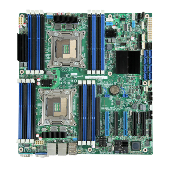
Page 20: Server Board Components
Server System Features Server Board Components ® This section helps you identify the components and connectors on the Intel Server Board S2600CP. Callout Description Callout Description Slot 1, PCI Express* Gen3 System Fan 4 connector RMM4 LITE Internal eUSB SSD... -
Page 21: Intel ® Light-Guided Diagnostics
Chassis Intrusion Figure 8. Server Board Connector and Component Locations ® Intel Light-Guided Diagnostics ® The figure in below shows the locations of Diagnostic LEDs on Intel Server Board S2600CP. ® ® Intel Server Board S2600CP Intel Server System P4000CP Family Service Guide... -
Page 22: Figure 9. Intel Light-Guided Diagnostic Leds - Server Board
DIMM Fault LEDs on the server board help identify failed and failing DIMM slots. The DIMM fault LEDs turn on (amber) if there is a DIMM fault. ® ® Intel Server Board S2600CP Intel Server System P4000CP Family Service Guide... -
Page 23: System Jumpers
Server System Features System Jumpers ® The figure below shows the locations of System Jumpers on Intel Server Board S2600CP. Jumper Name Pins System Results Pins 1-2 should be connected for normal system operation. (Default) BIOS Recovery The main system BIOS does not boot with pins 2-3 connected. The system only boots from EFI- bootable recovery media with a recovery BIOS image present. -
Page 24: Hot-Swap Sas/Sata Backplane
The following diagrams show the location for each connector found on the backplane. 8 x 3.5-inch Hard Drive Backplane SAS/SATA Hot-swap Connectors Figure 11. 8x3.5 backplane – Front View ® ® Intel Server Board S2600CP Intel Server System P4000CP Family Service Guide... -
Page 25: Figure 12. 8X3.5 Backplane - Rear View
C In Connector Figure 12. 8x3.5 backplane – Rear View 8 x 2.5-inch Hard Drive Backplane SAS/SATA Hot-swap Connectors Figure 13. 8 x 2.5 backplane - Front View ® ® Intel Server Board S2600CP Intel Server System P4000CP Family Service Guide... -
Page 26: Intel Raid Expander Cards (Upgrade Option)
Figure 14. 8 x 2.5 backplane - Rear View ® Intel RAID Expander Cards (Upgrade Option) Intel provides two types of internal RAID expander cards: 36 ports and 24 ports. Power Connector Mini-SAS Connector A Mini-SAS Connector B Mini-SAS Connector G (36 port sku only) -
Page 27: Advanced Management Options
It also provides Remote KVM Redirection and USB Media Redirection allowing USB devices attached to the remote system to be used on the managed server. ® For instructions on installing the Intel Remote Management Module 4, see “Installing and ®... -
Page 28: Hardware Installations And Upgrades
All references to left, right, front, top, and bottom assume the reader is facing the front of the chassis as it would be positioned for normal operation. ® ® Intel Server Board S2600CP Intel Server System P4000CP Family Service Guide... -
Page 29: Cable Routing Recommendations
Use the figures below to determine the correct cable routing. NOTE: ® To activate the port SATA/SAS 4-7 on the server board, a proper Intel RAID C600 Upgrade Key ® must be installed. For instructions, see Intel RAID C600 Upgrade Key Installation Guide. -
Page 30: Figure 17. Cable Routing For Intel
MiniSAS and SGPIO Cable PMBus Hot-swap Backplane I2C Cable System Fan 1 Cable System Fan 2 Cable ® Figure 17. Cable routing for Intel Server System P4308CP4MHEN ® ® Intel Server Board S2600CP Intel Server System P4000CP Family Service Guide... -
Page 31: Figure 18. Cable Connections For Intel Server System P4308Cp4Mhgc And P4208Cp4Mhgc
Hardware Installations and Upgrades ® Cable connections for Intel Server System P4308CP4MHGC and P4208CP4MHGC: ® Figure 18. Cable connections for Intel Server System P4308CP4MHGC and P4208CP4MHGC ® ® Intel Server Board S2600CP Intel Server System P4000CP Family Service Guide (Preliminary) -
Page 32: Figure 19. Cable Routing For Intel
Hot-swap Backplane I2C Cable System FAN 1 System FAN 2 System FAN 3 System FAN 4 System FAN5 ® Figure 19. Cable routing for Intel Server System P4308CP4MHGC and P4208CP4MHGC ® ® Intel Server Board S2600CP Intel Server System P4000CP Family Service Guide... -
Page 33: Removing And Installing The System Side Cover
4. Remove the screws (see letter "A"). 5. Slide the side cover back (see letter "B") and lift the cover outward to remove it. Figure 20. Removing the Side Cover ® ® Intel Server Board S2600CP Intel Server System P4000CP Family Service Guide (Preliminary) -
Page 34: Installing The System Side Cover
(see letter “A”) no more than 40 degrees outward. 5. At a 40-degree angle, push the bezel assembly away from the chassis (see letter “B”). ® ® Intel Server Board S2600CP Intel Server System P4000CP Family Service Guide... -
Page 35: Installing The Front Bezel
4. Latch the two plastic tabs (see letter “B”) on the left side of the bezel assembly to the chassis. Figure 23. Installing the Front Bezel ® ® Intel Server Board S2600CP Intel Server System P4000CP Family Service Guide (Preliminary) -
Page 36: Removing And/Or Installing Airduct
Remove the chassis cover. For instructions, see “Removing the Chassis Cover”. Install the airduct by matching the alignment tabs on airduct and the alignment holes on chassis bracket. ® ® Intel Server Board S2600CP Intel Server System P4000CP Family Service Guide... -
Page 37: Removing And Installing Processor
Similarly, loosen screws 3 and 4. Repeat steps A and B by giving each screw two rotations each time until all screws are loosened. 3. Lift the heatsink straight up (see letter “C”). ® ® Intel Server Board S2600CP Intel Server System P4000CP Family Service Guide (Preliminary) -
Page 38: Installing The Processor
2. Open the Load Plate. Press the locking lever slightly to raise the load plate (see letter “A”). Open the load plate all the way (see letter “B”). ® ® Intel Server Board S2600CP Intel Server System P4000CP Family Service Guide... -
Page 39: Figure 28. Installing Processor - Open The Load Plate
4. Remove the Cover. Press the cover to remove it. Save the protective cover. Figure 30. Installing Processor – Remove the Cover 5. Close the Load Plate. Carefully lower the load plate over the processor. ® ® Intel Server Board S2600CP Intel Server System P4000CP Family Service Guide (Preliminary) -
Page 40: Installing Processor Heatsink(S)
3 and 4 (see letter “C”). 5. Repeat these steps on each screw with two rotations each time until each screw is lightly tightened up to a maximum of 8 inch-lbs torque. ® ® Intel Server Board S2600CP Intel Server System P4000CP Family Service Guide... -
Page 41: Installing And Removing Memory
DIMM until the retaining clips snap into place (see letter “D”). Make sure the clips are firmly in place (see letter “E”). Figure 34. Installing Memory ® ® Intel Server Board S2600CP Intel Server System P4000CP Family Service Guide (Preliminary) -
Page 42: Removing Memory
3. Install the hard disk drive using the same four screws as shown. Make sure the connector end of the drive matches the backplane connector (see letter “D”). ® ® Intel Server Board S2600CP Intel Server System P4000CP Family Service Guide... -
Page 43: Figure 37. Installing Hard Disk Drive - Installing 3.5" Hdd
4. With the lever open, insert the hard disk drive assembly into the chassis (see letter “A”). Push in the lever to lock it into place (see letter “B”). Figure 39. Installing Hard Disk Drive – Inserting 3.5” HDD assembly ® ® Intel Server Board S2600CP Intel Server System P4000CP Family Service Guide (Preliminary) -
Page 44: Installing A Hard Disk Drive Into 2.5" Hard Drive Carrier
4. With the lever open, insert the hard disk drive assembly into the chassis (see letter “G”), then push in the lever to lock it into place (see letter “H”). ® ® Intel Server Board S2600CP Intel Server System P4000CP Family Service Guide... -
Page 45: Installing And Removing A Pci Add-In Card
5. Remove the PCI slot shield from the chassis rear end. See letter A. Figure 44. Remove PCI slot shield 6. Open the PCI card retainer. See letter B. ® ® Intel Server Board S2600CP Intel Server System P4000CP Family Service Guide (Preliminary) -
Page 46: Figure 45. Open Pci Card Retainer
7. Open the PCI card retention device. See letter C. Figure 46. Open PCI card retention device 8. Align the PCI card and insert into place. See letter D. Figure 47. Install PCI card ® ® Intel Server Board S2600CP Intel Server System P4000CP Family Service Guide... -
Page 47: Removing A Pci Add-In Card
4. Remove the airduct by gentlely lifting the airduct out of chassis. 5. Open the PCI card retainer. 6. Release PCI card retention device, remove screw if there is. ® ® Intel Server Board S2600CP Intel Server System P4000CP Family Service Guide (Preliminary) -
Page 48: Design A Gpgpu Card Extender
Users need to design a GPGPU card extender to make a non-full length GPGPU card to be full length, in order to take advandage of the GPGPU card bracket. Figure 51. Secure the GPGPU card with GPGPU bracket ® ® Intel Server Board S2600CP Intel Server System P4000CP Family Service Guide... -
Page 49: Installing And Removing An Optical Drive
To maintain proper system cooling, a filler panel must be installed if you do not install a device at this location. Installing an Optical Drive 1. Remove the O filler (see letter “A”). ® ® Intel Server Board S2600CP Intel Server System P4000CP Family Service Guide (Preliminary) -
Page 50: Removing An Optical Drive
2. Press the latching end of optical drive rails (see letter “A”) and pull the optical drive out (see letter “B”). 3. Remvoe the optical drive rail from the drive (see letter “C”). Figure 56. Remove an Optical Drive ® ® Intel Server Board S2600CP Intel Server System P4000CP Family Service Guide... -
Page 51: Installing And Removing The Intel
® Installing the Intel RAID C600 Upgrade Key ® Locate the white 4-pin key header. Carefully pickup the Intel RAID C600 Upgrade Key. Match the Key and connector orientation and press down to install. ® Figure 58. Installing the Intel RAID C600 Upgrade Key ®... -
Page 52: Installing And Removing The Intel
® Installing the Intel RMM4 Lite ® Locate the RMM4 Lite connector next to RISER SLOT_1, carefully pickup the Intel RMM4 Lite module, match the alignment pin of the module and the connector on server board, then press to install. -
Page 53: Removing The Intel Rmm4 Lite
® Installing the Intel RAID Smart Battery ® 1. Connect the cable between the BBU and the RAID card. For details, see Intel RAID Smart Battery User’s Guide. 2. Locate the mounting holes inside the chassis. 3. Align the tabs on the plastic battery holder with the mounting holes in the chassis and slide the plastic battery holder until the tabs engage with the mounting holes. -
Page 54: Removing The Intel Raid Smart Battery
Hardware Installations and Upgrades ® Figure 62. Installing the Intel RAID Smart Battery ® Removing the Intel RAID Smart Battery 1. Pull the tab until the tab is disengaged from the chassis cut. 2. Slide the battery from the server chassis side wall and move it out of the opening in the fan bulkhead. -
Page 55: Installing The Fixed Power Supply
4. Install the chassis cover. For instructions, see “Installing the Chassis Cover”. 5. Plug all peripheral devices and the AC power cable into the server. 6. Power up the server. ® ® Intel Server Board S2600CP Intel Server System P4000CP Family Service Guide (Preliminary) -
Page 56: Installing An Additional Hot-Swap Power Supply Module
2. Remove power cable from defective power supply. 3. Press up on green latch in the direction shown while pulling on handle to remove hot swap power supply from chassis. ® ® Intel Server Board S2600CP Intel Server System P4000CP Family Service Guide... -
Page 57: Replacing The Power Distribution Board
6. If present, press on green latch in the direction shown while pulling on handle to remove power supply from chassis. Repeat this step for the second hot-swap power supply if it is installed. ® ® Intel Server Board S2600CP Intel Server System P4000CP Family Service Guide (Preliminary) -
Page 58: Figure 70. Removing Hot-Swap Power Supply Module From Chassis
Figure 71. Loosing the Bracket with Power Distribution Board from Chassis 8. Push the bracket forward to release the latch which secure the bracket then pull out the bracket from the chassis (see letter “C”). ® ® Intel Server Board S2600CP Intel Server System P4000CP Family Service Guide... -
Page 59: Figure 72. Removing The Bracket With Power Distribution Board From Chassis
10. Slide the new power distribution board to the bracket (see letter “E”) and secure the new power distribution board to the bracket using the same screws (see letter “F”). ® ® Intel Server Board S2600CP Intel Server System P4000CP Family Service Guide (Preliminary) -
Page 60: Figure 74. Sliding The New Power Distribution Board In Bracket
Figure 75. Securing the New Power Distribution Board in Bracket 11. Slide the bracket with the new power distribution board all the way into the power supply cage (see letter “G”). ® ® Intel Server Board S2600CP Intel Server System P4000CP Family Service Guide... -
Page 61: Figure 76. Sliding The Bracket Into Power Supply Cage
(see letter “H”). And then secure the bracket with the screws (see letter “I” and “J”). Figure 77. Secruing the Bracket into Power Supply Cage 13. Reconnect the power cables as appropriate. ® ® Intel Server Board S2600CP Intel Server System P4000CP Family Service Guide (Preliminary) -
Page 62: Installing And Removing The Server Board
3. Lift the air duct side wall to remove from the server board. 4. Remove the nine screws from the server board (see letter “A”). 5. Lift the server board from the server system (see letter “B”). ® ® Intel Server Board S2600CP Intel Server System P4000CP Family Service Guide... -
Page 63: Installing The Server Board
2. Place the server board into the server system (see letter “A”). 3. Secure the server board with nine screws (see letter “B”). Figure 80. Installing the Server Board ® ® Intel Server Board S2600CP Intel Server System P4000CP Family Service Guide (Preliminary) -
Page 64: Replacing A Fixed Fan
2 bracket and the fan with white connector should be installed in fan 1 bracket. The fan numbering is inscribed on the chassis. ® This procedure applies only to the Intel Server Chassis P4000M family with fixed fan configuration. -
Page 65: Installing The Fixed Fan
Install the fixed fan in the corresponding fan bracket (see letter “B”). Figure 84. Installing the Fixed Fan 7. Connect fan power cable to the server/workstation board. See the Quick Start User’s Guide or Service Guide provided with your Intel server/workstation board for appropriate connection location. ®... -
Page 66: Replacing A Hot-Swap Fan
Hardware Installations and Upgrades Replacing a Hot-swap Fan NOTE ® This procedure applies only to the Intel Server Chassis P4000M family with hot-swap fan configuration. Removing the Hot-swap Fan 1. Observe the safety and ESD precautions at the beginning of this book. -
Page 67: Removing And Installing 8X3.5" Hot-Swap Hard Drive Cage Assembly
6. Use screwdriver to release the hot-swap hard drive cage (see letter “A”) from the chassis and remove the hot-swap hard drive cage (see letter “B”). Figure 87. Removing the 8x3.5” Hot-swap HDD Cage Assembly ® ® Intel Server Board S2600CP Intel Server System P4000CP Family Service Guide (Preliminary) -
Page 68: Installing 8X3.5" Hot-Swap Hard Drive Cage Assembly
RAID controller card. A. Connect an I2C cable (letter “A`”). B. Connect Mini SAS data cables (letter “B”). C. Connect power cable (letter “C”). ® ® Intel Server Board S2600CP Intel Server System P4000CP Family Service Guide... -
Page 69: Removing And Installing 8X2.5" Hot-Swap Hard Drive Cage Assembly
6. Use screwdriver to release the hot-swap hard drive cage (see letter “A”) from the chassis and remove the hot-swap hard drive cage (see letter “B”). ® ® Intel Server Board S2600CP Intel Server System P4000CP Family Service Guide (Preliminary) -
Page 70: Installing 8X2.5" Hot-Swap Hard Drive Cage Assembly
5. Install the 8x2.5” Hot-Swap Hard Drive Cage. A. Slide the 8x2.5” Hot-Swap Drive Cage into the slot (see letter “A”). B. Secure the Hard Drive Cage with the Screw (see letter “B”). ® ® Intel Server Board S2600CP Intel Server System P4000CP Family Service Guide... -
Page 71: Figure 91. Installing The 8X2.5" Hot-Swap Hard Drive Cage Assembly
9. Install the chassis cover. For instructions, see “Installing the Chassis Cover”. 10. Plug all peripheral devices and the AC power cable into the server. 11. Power up the server. ® ® Intel Server Board S2600CP Intel Server System P4000CP Family Service Guide (Preliminary) -
Page 72: Removing And Installing The Hot-Swap Hdd Emi Shiled
Hardware Installations and Upgrades Removing and Installing the Hot-swap HDD EMI Shiled NOTE ® This procedure applies only to the Intel Server Chassis P4000M family with 8x2.5” hot-swap hard disk drive cage configuration. Removing the Hot-swap HDD EMI Shiled 1. Observe the safety and ESD precautions at the beginning of this book. -
Page 73: Replacing The Backplane
C. Remove the screw as shown (see letter “A”); D. Slide the backplane (see letter “B”); E. Remove the backplane from the server chassis (see letter “C”). ® ® Intel Server Board S2600CP Intel Server System P4000CP Family Service Guide (Preliminary) -
Page 74: Figure 96. Removing 3.5" Hard Drive Backplane - Remove The Backplane
D. Slide the backplane board to release it (see letter “B”); E. Remove the backplane board from the four hooks and pull out of the hard drive cage (see letter “C”). ® ® Intel Server Board S2600CP Intel Server System P4000CP Family Service Guide... -
Page 75: Installing The Backplane
A. Align the backplane board with the hooks on the hard drive cage (see letter “A”); B. Slide the backplane into the drive cage (see letter “B”); C. Secure the backplane with screws (see letter “C”); ® ® Intel Server Board S2600CP Intel Server System P4000CP Family Service Guide (Preliminary) -
Page 76: Figure 99. Installing 3.5" Hard Drive Backplane - Install The Backplane
B. Slide the backplane board in the direction shown to lock it in place (see letter “B”); C. Secure the backplane with the screw as shown (see letter “C”); ® ® Intel Server Board S2600CP Intel Server System P4000CP Family Service Guide... -
Page 77: Removing And Installing The Top Cosmetic Cover
Observe the safety and ESD precautions at the beginning of this book. Power down the server and unplug all peripheral devices and the AC power cable. Remove the chassis cover. For instructions, see “Removing the Chassis Cover”. ® ® Intel Server Board S2600CP Intel Server System P4000CP Family Service Guide (Preliminary) -
Page 78: Installing The Top Cosmetic Cover
Figure 104. Installing the Top Cosmetci Cover Removing and Installing the Chassis Feet Removing the Chassis Feet 1. Observe the safety and ESD precautions at the beginning of this book. ® ® Intel Server Board S2600CP Intel Server System P4000CP Family Service Guide... -
Page 79: Installing The Chassis Feet (Pedestal Configuration Only)
Installing the Chassis Feet (Pedestal Configuration Only) NOTE ® Do not install feet on your Intel Server Chassis P4000M family if it is to be installed in a rack. Only install feet on a pedestal-configured chassis. 1. Observe the safety and ESD precautions at the beginning of this book. -
Page 80: Removing And Installing The Front Panel Tray
4. Remove the front bezel if it is installed. For instructions, see “Removing the Front Bezel”. 5. Remove the air duct if it is installed. 6. Disconnect the front panel cable, USB cable from the server board ® ® Intel Server Board S2600CP Intel Server System P4000CP Family Service Guide... -
Page 81: Figure 107. Disconnecting The Cables From The Server Board
Then disconnect the front panel cable and intrusion switch cable from the front panel board (see Letter “D”). ® ® Intel Server Board S2600CP Intel Server System P4000CP Family Service Guide (Preliminary) -
Page 82: Installing The Fron Panel Tray
6. Attach the front panel cable and the chassis intrusion cable (see Letter “A”) to the front panel board. Figure 110. Connecting the Cables to the Front Panel Board ® ® Intel Server Board S2600CP Intel Server System P4000CP Family Service Guide... -
Page 83: Replacing The Front Panel Board
3. Remove the chassis cover. For instructions, see “Removing the Chassis Cover”. 4. Remove the front bezel if it is installed. For instructions, see “Removing the Front Bezel”. ® ® Intel Server Board S2600CP Intel Server System P4000CP Family Service Guide (Preliminary) -
Page 84: Figure 113. Removing The Front Panel Board
10. Install the front bezel. For instructions, see “Removing and Installing the Front Bezel”. 11. Install the air duct based on board requirement. 14. Install the chassis cover. For instructions, see “Installing the Chassis Cover”. ® ® Intel Server Board S2600CP Intel Server System P4000CP Family Service Guide... -
Page 85: Installing Alternate Serial Port
5. Install the serial port on the rear panel of the chassis. And connect the cable to the Serial B Connector on your motherboard. Figure 117. Installing the Alternate Serial Port Knockout ® ® Intel Server Board S2600CP Intel Server System P4000CP Family Service Guide (Preliminary) -
Page 86: Installing And/Or Removing A Expander Card
1. Observe the safety and ESD precautions at the beginning of this book. 2. Power down the server and unplug all peripheral devices and the AC power cable. 3. Remove the chassis cover. For instructions, “Removing the Chassis Cover”. ® ® Intel Server Board S2600CP Intel Server System P4000CP Family Service Guide... -
Page 87: Figure 119. Removing The Expander Card
9. Install the fans. For instructions, see “Install the Fixed Fan” or “Install the Hot-swap Fans”. 10. Install the chassis cover. For instructions, see “Install the Chassis Cover”. ® ® Intel Server Board S2600CP Intel Server System P4000CP Family Service Guide (Preliminary) -
Page 88: Server Utilities
To enter the BIOS Setup using a keyboard (or emulated keyboard); press the <F2> function key ® during boot time when the OEM or Intel logo is displayed. The following message is displayed on the diagnostics screen and under the Quiet Boot logo screen: Press <F2>... -
Page 89: Setup Screen Menu Selection Bar
The text shown in the Option Values and Help Text entries in each Field Description are the actual text and values are displayed on the BIOS Setup screens. ® ® Intel Server Board S2600CP Intel Server System P4000CP Family Service Guide (Preliminary) -
Page 90: Map Of Screens And Functionality
Advanced Screen (Tab) Processor Configuration Memory Configuration Memory RAS and Performance Configuration Mass Storage Controller Configuration PCI Configuration Serial Port Configuration ® ® Intel Server Board S2600CP Intel Server System P4000CP Family Service Guide... - Page 91 Add EFI Boot Option Delete EFI Boot Option Boot Manager Screen (Tab) Error Manager Screen (Tab) [Non-BMC Only] View Event Log Screen Exit Screen (Tab) ® ® Intel Server Board S2600CP Intel Server System P4000CP Family Service Guide (Preliminary)
-
Page 92: Main Screen (Tab)
Comments: Information only. Displays password level that setup is running in: Administrator or User. With no passwords set, Administrator is the default mode. Back to [Main Screen] ® ® Intel Server Board S2600CP Intel Server System P4000CP Family Service Guide... - Page 93 BIOS ID String, with the timestamp segment dropped off. The segments displayed are: Platform: Identifies that this is the correct platform BIOS 86B: Identifies this BIOS as being an Intel Server BIOS Major Revision level of the BIOS Release Revision level for this BIOS zzzz: Release Number for this BIOS...
- Page 94 It may be edited to change the system date. When the System Date is reset by the “BIOS Defaults” jumper, BIOS Recovery Flash Update, or other method, the date will be the earliest date in the allowed range – Saturday 01/01/2005. Back to [Main Screen] ® ® Intel Server Board S2600CP Intel Server System P4000CP Family Service Guide...
- Page 95 BIOS Recovery Flash Update, or other method, the time will be the earliest time of day in the allowed range – 00:00:00 (although the time will be updated beginning from when it is reset early in POST). Back to [Main Screen] ® ® Intel Server Board S2600CP Intel Server System P4000CP Family Service Guide (Preliminary)
-
Page 96: Advanced Screen (Tab)
View/Configure memory information and settings. Comments: Selection only. Position to this line and press the <Enter> key to go to the Memory Configuration group of configuration settings. Back to [Advanced Screen] ® ® Intel Server Board S2600CP Intel Server System P4000CP Family Service Guide... - Page 97 Selection only. Position to this line and press the <Enter> key to go to the System Acoustic and Performance Configuration group of configuration settings. Back to [Advanced Screen] ® ® Intel Server Board S2600CP Intel Server System P4000CP Family Service Guide (Preliminary)
-
Page 98: Processor Configuration
To access this screen from the Main screen, select Advanced > Processor Configuration. To move to another screen, press the <Esc> key to return to the Advanced screen, then select the desired screen. ® ® Intel Server Board S2600CP Intel Server System P4000CP Family Service Guide... -
Page 99: Figure 122. Processor Configuration Screen
DCU Data Prefetcher Enabled/Disabled DCU Instruction Prefetcher Enabled/Disabled Direct Cache Access (DCA) Enabled/Disabled Enhanced Error Containment Mode Enabled/Disabled SMM Wait Timeout [0 – 3000ms, 3 is default] ® ® Intel Server Board S2600CP Intel Server System P4000CP Family Service Guide (Preliminary) - Page 100 Single socket boards have a single processor display, 2 sockets or 4 sockets boards have a display column for each socket, showing “N/A” for empty sockets where processors are not installed. Back to [Processor Configuration Screen] — [Advanced Screen] ® ® Intel Server Board S2600CP Intel Server System P4000CP Family Service Guide...
- Page 101 Single socket boards have a single processor display, 2 sockets or 4 sockets boards have a display line for each socket, showing “N/A” for empty sockets where processors are not installed. Back to [Processor Configuration Screen] — [Advanced Screen] ® ® Intel Server Board S2600CP Intel Server System P4000CP Family Service Guide (Preliminary)
- Page 102 Help Text: ® Allows for selecting the Intel QuickPath Interconnect Frequency. Recommended to ® leave in [Auto Max] so that BIOS can select the highest common Intel QuickPath Interconnect frequency. Comments: Lowering the QPI frequency may improve performance per watt for some processing loads and on certain benchmarks.
- Page 103 Comments: When Disabled, the processor setting reverts to running at Max TDP Core Frequency (rated frequency). ® This option is only visible if all processors installed in the system support Enhanced Intel ® ® SpeedStep Technology. In order for the Intel Turbo Boost option to be available, Enhanced ®...
- Page 104 Execute Disable Bit. The OS and applications installed must support this feature in order for it to be enabled. Back to [Processor Configuration Screen] — [Advanced Screen] ® ® Intel Server Board S2600CP Intel Server System P4000CP Family Service Guide...
- Page 105 Disabled Help Text: ® ® Enable/Disable Intel Virtualization Technology for Directed I/O (Intel VT-d). Report the I/O device assignment to VMM through DMAR ACPI Tables. Comments: This option is only visible if all processors installed in the system support ®...
- Page 106 Trusted Execution Technology. Takes effect after reboot. ® Comments: Intel TXT only appears when Intel Virtualization Technology is enabled. This option appears only on models equipped with a TPM. The TPM must be active in order to ® support Intel TXT.
- Page 107 Cache and Memory Channel use, but disabling it may improve performance for some processing loads and on certain benchmarks. Back to [Processor Configuration Screen] — [Advanced Screen] ® ® Intel Server Board S2600CP Intel Server System P4000CP Family Service Guide (Preliminary)
- Page 108 System performance is usually best with Direct Cache Access Enabled. In certain unusual cases, disabling this may give improved results. Back to [Processor Configuration Screen] — [Advanced Screen] ® ® Intel Server Board S2600CP Intel Server System P4000CP Family Service Guide...
-
Page 109: Memory Configuration
To access this screen from the Main screen, select Advanced > Memory Configuration. To move to another screen, press the <Esc> key to return to the Advanced screen, then select the desired screen. ® ® Intel Server Board S2600CP Intel Server System P4000CP Family Service Guide (Preliminary) -
Page 110: Figure 123. Memory Configuration Screen
Information only. Displays the amount of memory available in the system in the form of installed DDR3 DIMMs, in units of GB. Back to [Memory Configuration Screen] — [Advanced Screen] ® ® Intel Server Board S2600CP Intel Server System P4000CP Family Service Guide... - Page 111 The supported memory speeds are 800 MT/s, 1066 MT/s, 1333 MT/s, and 1600 MT/s. The actual memory speed capability depends on the memory configuration. Back to [Memory Configuration Screen] — [Advanced Screen] ® ® Intel Server Board S2600CP Intel Server System P4000CP Family Service Guide (Preliminary)
- Page 112 When enabled, Demand Scrub automatically corrects a Correctable ECC Error encountered during a fetch from memory by writing back the corrected data to memory. Back to [Memory Configuration Screen] — [Advanced Screen] ® ® Intel Server Board S2600CP Intel Server System P4000CP Family Service Guide...
- Page 113 When enabled, the system is configured to allow memory power management by the Node Manager (NM) and Management Engine (ME). Back to [Memory Configuration Screen] — [Advanced Screen] ® ® Intel Server Board S2600CP Intel Server System P4000CP Family Service Guide (Preliminary)
- Page 114 1 - 3 within the Channel. DIMM_A2 is the DIMM socket on Channel A, Slot 2. Not all boards have the same number of channels and slots – this is dependent on the board features. ® ® Intel Server Board S2600CP Intel Server System P4000CP Family Service Guide...
-
Page 115: Memory Ras And Performance Configuration
Performance Configuration. To move to another screen, press the <Esc> key to return to the Memory Configuration screen, if necessary press the <Esc> key again to return to the Advanced screen, then select the desired screen. ® ® Intel Server Board S2600CP Intel Server System P4000CP Family Service Guide (Preliminary) -
Page 116: Figure 124. Memory Ras And Performance Configuration Screen
(Mirroring Domain). Back to [Memory RAS and Performance Configuration Screen] — [Memory Configuration Screen] — [Advanced Screen] 2. Memory Rank Sparing Possible Option Values: Help Text: <None> ® ® Intel Server Board S2600CP Intel Server System P4000CP Family Service Guide... - Page 117 Memory Lockstep. For Memory Lockstep to be possible, DIMM configurations on all paired channels must be identical between the channel pair. Back to [Memory RAS and Performance Configuration Screen] — [Memory Configuration Screen] — [Advanced Screen] ® ® Intel Server Board S2600CP Intel Server System P4000CP Family Service Guide (Preliminary)
- Page 118 Back to [Memory RAS and Performance Configuration Screen] — [Memory Configuration Screen] — [Advanced Screen] ® ® Intel Server Board S2600CP Intel Server System P4000CP Family Service Guide...
-
Page 119: Mass Storage Controller Configuration
Storage Control Unit (SCU) with SATA or SAS drive support and RAID support. There are also informational displays of AHCI and SCU controller configuration, and SATA Drive Information when ® applicable. If the presence of an Intel Storage Module is detected, the type of Storage Module is displayed as information-only. - Page 120 SCU controller, and whether they are configured for SATA or SAS. This information is also displayed during POST in the POST Diagnostic Screen. ® Various SATA/SAS Capable Controller configurations require the installation of Intel RAID C600 Upgrade Keys:...
- Page 121 - Intel ESRT2 (Powered By LSI*): Supports RAID 0/1/10 and optional RAID 5 with ® Intel RAID C600 Upgrade Keys. Uses Intel ESRT2 drivers (based on LSI* MegaSR). ® - Intel RSTe: Provides pass-through drive support. Also provides host based RAID ®...
- Page 122 ® Intel RSTe provides pass-through drive support and provides host based RAID 0/1/10 support, and RAID 5 (in SATA mode only). Uses Intel RSTe drivers in Windows, and MDRAID stack in ® Linux. The Intel RSTe RAID stack is required if it is necessary to provide pass-through support for non-RAID drives, or if support is needed for more than 8 drives.
- Page 123 ® Comments: This option appears only when Intel RSTe has been selected as the operational mode on both the AHCI and SCU controllers. In that case there is a conflict and only one controller can be selected as having bootable drives attached.
-
Page 124: Pci Configuration
The PCI Configuration screen allows the user to configure the PCI memory space used for onboard and add-in adapters, configure video options, and configure onboard adapter options. It also includes a selection option to go to the NIC Configuration screen. ® ® Intel Server Board S2600CP Intel Server System P4000CP Family Service Guide... -
Page 125: Figure 126. Pci Configuration Screen
64-bit addressing is allocated to address space above 4GB, in order to allow larger allocations and avoid impacting address space below 4G. Back to [PCI Configuration Screen] — [Advanced Screen] ® ® Intel Server Board S2600CP Intel Server System P4000CP Family Service Guide (Preliminary) - Page 126 NOTE This option does not appear on some models. Back to [PCI Configuration Screen] — [Advanced Screen] ® ® Intel Server Board S2600CP Intel Server System P4000CP Family Service Guide...
-
Page 127: Nic Configuration
To move to another screen, press the <Esc> key to return to the PCI Configuration screen, if necessary press the <Esc> key again to return to the Advanced screen, then select the desired screen. ® ® Intel Server Board S2600CP Intel Server System P4000CP Family Service Guide (Preliminary) -
Page 128: Figure 127. Nic Configuration Screen
WOL only with an ACPI-capable Operating System which has the WOL function enabled. Back to [NIC Configuration Screen] — [PCI Configuration Screen] — [Advanced Screen] ® ® Intel Server Board S2600CP Intel Server System P4000CP Family Service Guide... - Page 129 Address display will not appear when this option is disabled. This option will not appear when NIC<n> is disabled. Back to [NIC Configuration Screen] — [PCI Configuration Screen] — [Advanced Screen] ® ® Intel Server Board S2600CP Intel Server System P4000CP Family Service Guide (Preliminary)
- Page 130 If both of the onboard NIC are enabled and the iSCSI Option ROM is disabled, the onboard NICs cannot be booted and cannot Wake-on-LAN. This option does not appear on some models. Back to [NIC Configuration Screen] — [PCI Configuration Screen] — [Advanced Screen] ® ® Intel Server Board S2600CP Intel Server System P4000CP Family Service Guide...
-
Page 131: Serial Port Configuration
To access this screen from the Main screen, select Advanced > Serial Port Configuration. To move to another screen, press the <Esc> key to return to the Advanced screen, then select the desired screen. ® ® Intel Server Board S2600CP Intel Server System P4000CP Family Service Guide (Preliminary) -
Page 132: Figure 128. Serial Port Configuration Screen
Select Serial port A base I/O address. Comments: Legacy I/O port address. Back to [Serial Port Configuration] 3. IRQ Option Values: Help Text: Select Serial port A interrupt request (IRQ) line. ® ® Intel Server Board S2600CP Intel Server System P4000CP Family Service Guide... -
Page 133: Usb Configuration
Each USB Mass Storage device may be set to allow the media emulation for which it is formatted, or an emulation may be specified. For USB Flash Memory devices in particular, there are some restrictions: ® ® Intel Server Board S2600CP Intel Server System P4000CP Family Service Guide (Preliminary) -
Page 134: Figure 129. Usb Configuration Screen
<Number of USB devices detected in system> Help Text: <None> Comments: Information only. Displays the total number of USB devices of all types which have been detected in POST. Back to [USB Configuration] ® ® Intel Server Board S2600CP Intel Server System P4000CP Family Service Guide... - Page 135 Exclude USB in Boot Table. [Enabled]- This will remove all USB Mass Storage devices as Boot options. [Disabled] - This will allow all USB Mass Storage devices as Boot options. ® ® Intel Server Board S2600CP Intel Server System P4000CP Family Service Guide (Preliminary)
-
Page 136: System Acoustic And Performance Configuration
To access this screen from the Main screen, select Advanced > System Acoustic and Performance Configuration. To move to another screen, press the <Esc> key to return to the Advanced screen, then select the desired screen. ® ® Intel Server Board S2600CP Intel Server System P4000CP Family Service Guide... -
Page 137: Figure 130. System Acoustic And Performance Configuration
DCLTT is the expected mode for a board in an Intel chassis with inlet and outlet air temperature sensors and TSOD. The firmware can update the offset registers for closed loop during runtime, as BIOS sends the dynamic CLTT offset temperature data. - Page 138 This is a percentage by which the calculated fan speed will be increased. The user can apply positive offsets that result in increasing the minimum fan speeds. Back to [System Acoustic and Performance Configuration] ® ® Intel Server Board S2600CP Intel Server System P4000CP Family Service Guide...
-
Page 139: Security Screen (Tab)
Trusted Platform Module (TPM) security settings on those boards that support TPM. ® Note that it is necessary to activate the TPM in order be able to enable Intel Trusted Execution Technology (TXT) on boards that support it. Changing the TPM state in Setup will require a Hard Reset ®... - Page 140 User password is used if Power On Password is enabled and to allow restricted access to BIOS Setup. Length is 1-14 characters. Case sensitive alphabetic, numeric and special characters !@#$%^&*()-_+=? are allowed. Note: Removing the administrator password also removes the user password. ® ® Intel Server Board S2600CP Intel Server System P4000CP Family Service Guide...
- Page 141 NMI Diagnostic Interrupt is not available. Comments: This option does not appear on all boards. Back to [Security Screen] ® ® Intel Server Board S2600CP Intel Server System P4000CP Family Service Guide (Preliminary)
- Page 142 Any Administrative Control operation selected will require the system to perform a Hard Reset in order to become effective. NOTE This option appears only on boards equipped with a TPM. Back to [Security Screen] ® ® Intel Server Board S2600CP Intel Server System P4000CP Family Service Guide...
-
Page 143: Server Management Screen (Tab)
To access this screen from the Main screen or other top-level “Tab” screen, press the right or left arrow keys to traverse the tabs at the top of the Setup screen until the Server Management screen is selected. ® ® Intel Server Board S2600CP Intel Server System P4000CP Family Service Guide (Preliminary) -
Page 144: Figure 132. Server Management Screen
“Catastrophic Error” CATERR# signal is held asserted, rather than just pulsed to generate an SMI. This indicates that the processor has encountered a fatal hardware error. Back to [Server Management Screen] ® ® Intel Server Board S2600CP Intel Server System P4000CP Family Service Guide... -
Page 145: Console Redirection
To access this screen from the Main screen, select Server Management > Console Redirection. To move to another screen, press the <Esc> key to return to the Server Management screen, then select the desired screen. ® ® Intel Server Board S2600CP Intel Server System P4000CP Family Service Guide (Preliminary) -
Page 146: System Information
To access this screen from the Main screen, select Server Management > System Information. To move to another screen, press the <Esc> key to return to the Server Management screen, then select the desired screen. ® ® Intel Server Board S2600CP Intel Server System P4000CP Family Service Guide... -
Page 147: Bmc Lan Configuration
To access this screen from the Main screen, select Server Management > System Information. To move to another screen, press the <Esc> key to return to the Server Management screen, then select the desired screen. ® ® Intel Server Board S2600CP Intel Server System P4000CP Family Service Guide (Preliminary) -
Page 148: Figure 135. Bmc Lan Configuration Screen
[0.0.0.0 IP display/edit] Subnet Mask [0.0.0.0 IP display/edit] Gateway IP [0.0.0.0 IP display/edit] Baseboard LAN IPV6 configuration IPV6 Enable/Disabled Intel (R) RMM4 IPV4 LAN configuration Intel (R) RMM4 <Present/Not Present> IP Source Static/Dynamic IP Address [0.0.0.0 IP display/edit] Subnet Mask [0.0.0.0 IP display/edit]... - Page 149 This specifies the IPv4 addressing Subnet Mask for the Baseboard LAN. ® There is a separate IPv4 Subnet Mask field for the Intel RMM4 LAN configuration. When IPv4 addressing is used, the initial value for this field is acquired from the BMC. The setting of IP Source determines whether this field is display-only (when Dynamic) or can be edited (when Static).
- Page 150 This specifies the IP Source for IPv6 addressing for the Baseboard LAN ® configuration. There is a separate IPv6 Source field for the Intel RMM4 LAN configuration. This option is only visible when the IPv6 option is set to Enabled.
- Page 151 Comments: This specifies the Gateway IPv6 Address for the Baseboard LAN. There ® is a separate Gateway IPv6 Address field for the Intel RMM4 LAN configuration. This option is only visible when the IPv6 option is set to Enabled. When IPv6 addressing is used, the initial value for this field is acquired from the BMC. The setting of IPv6 Source determines whether this field is display-only (when Dynamic or Auto) or can be edited (when Static).
- Page 152 IP address is acquired automatically (DHCP). ® Comments: This specifies the IP Source for IPv4 addressing for the Intel RMM4 DMN LAN connection. There is a separate IP Source field for the Baseboard LAN configuration. When IPv4 addressing is used, the initial value for this field is acquired from the BMC, and its ®...
- Page 153 View/Edit Subnet Mask. Press <Enter> to edit. ® Comments: This specifies the IPv4 addressing Subnet Mask for the Intel RMM4 DMN LAN. There is a separate IPv4 Subnet Mask field for the Baseboard LAN configuration. When IPv4 addressing is used, the initial value for this field is acquired from the BMC. The setting of IP Source determines whether this field is display-only (when Dynamic) or can be edited (when Static).
- Page 154 Hardware Installations and Upgrades ® Comments: This specifies the IP Source for IPv6 addressing for the Intel RMM4 DMN LAN configuration. There is a separate IPv6 Source field for the Baseboard LAN configuration. This option is only visible when the IPv6 option is set to Enabled.
- Page 155 Hardware Installations and Upgrades ® Comments: This specifies the IPv6 Prefix Length for the Intel RMM4 DMN LAN. There is a separate IPv6 Prefix Length field for the Baseboard LAN configuration. This option is only visible when the IPv6 option is set to Enabled.
- Page 156 Comments: User Name can only be edited for users other than “anonymous” and “root”. Those two User Names may not be changed. Back to [BMC LAN Configuration] ® ® Intel Server Board S2600CP Intel Server System P4000CP Family Service Guide...
-
Page 157: Boot Options Screen (Tab)
CDROM Drive, it will not be detected as such. It will be treated as a Hard Disk and will appear in the list of available Hard Drives. ® ® Intel Server Board S2600CP Intel Server System P4000CP Family Service Guide (Preliminary) -
Page 158: Figure 136. Boot Options Screen
After entering the desired timeout, press the <Enter> key to register that timeout value to the system. These settings are in seconds. The timeout value entered will take effect on the next boot. ® ® Intel Server Board S2600CP Intel Server System P4000CP Family Service Guide... - Page 159 This option appears when one or more bootable CDROM drives are available in the system. This includes USB CDROM devices, but not USB Keys formatted for CRDOM emulation, which are seen as Hard Disk drives. Back to [Boot Options Screen] ® ® Intel Server Board S2600CP Intel Server System P4000CP Family Service Guide (Preliminary)
- Page 160 Selection only. Position to this line and press the <Enter> key to go to the BEV Device Order Screen. This option appears when one or more bootable BEV Devices are available in the system. Back to [Boot Options Screen] ® ® Intel Server Board S2600CP Intel Server System P4000CP Family Service Guide...
- Page 161 If enabled, the BIOS uses the legacy video ROM instead of the EFI video ROM. Comments: This option appears only when EFI Optimized Boot is enabled. Back to [Boot Options Screen] ® ® Intel Server Board S2600CP Intel Server System P4000CP Family Service Guide (Preliminary)
- Page 162 When the option changes from “Enabled” to “Disabled”, this will disable SBO and the SBO template will be cleared. Otherwise it will retain the current Enabled/Disabled state. Back to [Boot Options Screen] ® ® Intel Server Board S2600CP Intel Server System P4000CP Family Service Guide...
-
Page 163: Cdrom Order
To access this screen from the Main screen, select Boot Options > CDROM Order. To move to another screen, press the <Esc> key to return to the Boot Options screen, then select the desired screen. ® ® Intel Server Board S2600CP Intel Server System P4000CP Family Service Guide (Preliminary) -
Page 164: Hard Disk Order
To access this screen from the Main screen, select Boot Options > Hard Disk Order. To move to another screen, press the <Esc> key to return to the Boot Options screen, then select the desired screen. ® ® Intel Server Board S2600CP Intel Server System P4000CP Family Service Guide... -
Page 165: Floppy Order
To access this screen from the Main screen, select Boot Options > Floppy Order. To move to another screen, press the <Esc> key to return to the Boot Options screen, then select the desired screen. ® ® Intel Server Board S2600CP Intel Server System P4000CP Family Service Guide (Preliminary) -
Page 166: Network Device Order
To access this screen from the Main screen, select Boot Options > Network Device Order. To move to another screen, press the <Esc> key to return to the Boot Options screen, then select the desired screen. ® ® Intel Server Board S2600CP Intel Server System P4000CP Family Service Guide... -
Page 167: Bev Device Order
To access this screen from the Main screen, select Boot Options > BEV Device Order. To move to another screen, press the <Esc> key to return to the Boot Options screen, then select the desired screen. ® ® Intel Server Board S2600CP Intel Server System P4000CP Family Service Guide (Preliminary) -
Page 168: Add Efi Boot Option
To access this screen from the Main screen, select Boot Options > Add EFI Boot Option. To move to another screen, press the <Esc> key to return to the Boot Options screen, then select the desired screen. ® ® Intel Server Board S2600CP Intel Server System P4000CP Family Service Guide... -
Page 169: Figure 142. Add Efi Boot Option Screen
This will be the Boot Path, residing on the filesystem chosen, which will entered into the Boot Order with the Label entered above. Back to [Add EFI Boot Option Screen] — [Boot Options Screen] ® ® Intel Server Board S2600CP Intel Server System P4000CP Family Service Guide (Preliminary) -
Page 170: Delete Efi Boot Option
Note that this list is not in order according to the system Boot Option order. The “Internal EFI Shell” will always be available, regardless of whether any other bootable devices are available. ® ® Intel Server Board S2600CP Intel Server System P4000CP Family Service Guide... -
Page 171: Error Manager Screen (Tab)
(noted in bold in the Setup screen images) are applied. If Load User Default Values is selected, the system is restored to previously saved user-defined default values. ® ® Intel Server Board S2600CP Intel Server System P4000CP Family Service Guide (Preliminary) -
Page 172: Figure 146. Exit Screen
Save Changes Discard Changes Load Default Values Save as User Default Values Load User Default Values *Certain brands and names may be claimed as the property of others. ® ® Intel Server Board S2600CP Intel Server System P4000CP Family Service Guide... -
Page 173: Appendix A: Technical Reference
19 A 30 A 16 A 30 A +12V1,2 29 A 36 A +12V3 (240VA limited) 18.5 A 20 A -12V No damage 5Vstby No damage ® ® Intel Server Board S2600CP Intel Server System P4000CP Family Service Guide (Preliminary) -
Page 174: 750-W Redundant Power Supply Input/Output Voltages
+/- 2 degrees C) Shock, operating Half sine, 2 g peak, 11 milliseconds Trapezoidal, 25 g, velocity change 136 inches/second ( ≧ 40 lbs to < 80 lbs) Shock, unpackaged ® ® Intel Server Board S2600CP Intel Server System P4000CP Family Service Guide... - Page 175 Non-palletized free fall in height 24 inches ( ≧ 40 lbs to < 80 lbs) Shock, packaged Vibration, unpackaged 5 Hz to 500 Hz, 2.20 g RMS random ® +/-15 KV except I/O port +/- 8 KV per Intel Environmental test specification System Cooling Requirement in 460 Watt Max – 1570 BTU/hour BTU/Hr 750 Watt Max –...
-
Page 176: Appendix B: Regulatory And Compliance Information
Appendix B: Regulatory and Compliance Information Please refer to the Server Products Regulatory and Safety document for the product regulatory compliance reference. The document can be downloaded from http://www.intel.com/support/motherboards/server/. ® ® Intel Server Board S2600CP Intel Server System P4000CP Family Service Guide... -
Page 177: Appendix C: Led Decoder
The diagnostic LED #7 is labeled as “MSB”, and the diagnostic LED #0 is labeled as “LSB”. System Status LED System Identification LED LSB 123456 MSB POST Code Diagnostic LEDs Figure 147. Diagnostic LED Placement Diagram ® ® Intel Server Board S2600CP Intel Server System P4000CP Family Service Guide (Preliminary) -
Page 178: Table 11. Post Progress Code Led Example
PEI Phase PEI Core CPU PEIM NB PEIM SB PEIM MRC Process Codes – MRC Progress Code Sequence is executed - See Table 63 PEI Phase continued… ® ® Intel Server Board S2600CP Intel Server System P4000CP Family Service Guide... - Page 179 DXE PCI Bus enumeration DXE PCI Bus resource requested DXE PCI Bus assign resource DXE CON_OUT connect DXE CON_IN connect DXE SIO Init DXE USB start ® ® Intel Server Board S2600CP Intel Server System P4000CP Family Service Guide (Preliminary)
- Page 180 DXE Configuration Reset INT19 S3 Resume S3 Resume PEIM (S3 started) S3 Resume PEIM (S3 boot script) S3 Resume PEIM (S3 Video Repost) S3 Resume PEIM (S3 OS wake) ® ® Intel Server Board S2600CP Intel Server System P4000CP Family Service Guide...
- Page 181 BIOS Recovery PEIM which detected forced Recovery condition PEIM which detected User Recovery condition Recovery PEIM (Recovery started) Recovery PEIM (Capsule found) Recovery PEIM (Capsule loaded) ® ® Intel Server Board S2600CP Intel Server System P4000CP Family Service Guide (Preliminary)
-
Page 182: Appendix D: Getting Help
A searchable knowledgebase to search for product information throughout the su.pport site. If you are still unable to obtain a solution to your issue, send an email to Intel’s technical support center using the online form available at http://www.intel.com/support/feedback.htm?group=server. -
Page 183: Appendix E: Intel Server Issue Report Form
Has the latest IMM BMC been tried? (Yes/No): Has the latest RMM Firmware been tried? (Yes/No): Has the latest FRU/SDR been tried? (Yes/No): Has the latest HSC been tried? (Yes/No): ® ® Intel Server Board S2600CP Intel Server System P4000CP Family Service Guide (Preliminary) - Page 184 Adapters, RAID Controllers, SCSI Controllers, and so on): Type Slot Manufacturer Model Firmware Other third part hardware (Example: Example: KVM, Chassis, and so on): Description/Use Manufacturer Model Firmware ® ® Intel Server Board S2600CP Intel Server System P4000CP Family Service Guide...
- Page 185 RAID volumes configuration (disks & RAID level): RAID volume use (Boot device/Data Volume): Is BBU (Battery Backup Unit) installed? (Yes/No): BBU part number: Detailed description of issue: ® ® Intel Server Board S2600CP Intel Server System P4000CP Family Service Guide (Preliminary)
- Page 186 ® Appendix E: Intel Server Issue Report Form Troubleshooting tried: Steps to replicate the issue: ® ® Intel Server Board S2600CP Intel Server System P4000CP Family Service Guide...
- Page 187 Server Issue Report Form Issue impact statements: Do you have any potential Intel system, or component purchases that this issue is holding up? If yes, please provide a brief description below. Do you have systems already purchased that are not being delivered to your customers because of this issue? If yes, please provide a brief description below.