Table of Contents
Advertisement
Quick Links
See also:
Manual
Advertisement
Table of Contents

Related Manuals for Intel S1400SP


Summary of Contents for Intel S1400SP
- Page 1 Intel Server Board S1400SP ® Technical Product Specification Intel order number G64248-003 Revision 2.1 May, 2014...
- Page 2 Revision History Intel® Server Board S1400SP TPS Revision History Date Revision Number Modifications September, 2012 Initial release. In Table 1, add a note that SAS Module and eUSB SSD can’t be December, 2013 supported at the same time. ®...
- Page 3 INFRINGEMENT OF ANY PATENT, COPYRIGHT OR OTHER INTELLECTUAL PROPERTY RIGHT. A "Mission Critical Application" is any application in which failure of the Intel Product could result, directly or indirectly, in personal injury or death. SHOULD YOU PURCHASE OR USE INTEL'S PRODUCTS FOR ANY SUCH MISSION...
-
Page 4: Table Of Contents
Server Board Use Disclaimer .................. 1 2. Overview ..........................2 ® 2.1 Intel Server Boards S1400SP Feature Set ............2 2.2 Server Board Layout ....................4 2.2.1 Server Board Connector and Component Layout ............ 5 ... - Page 5 Intel® Server Board S1400SP TPS Table of Contents 6.1.1 IPMI 2.0 Features ....................47 6.1.2 Non IPMI Features ....................48 6.1.3 New Manageability Features ................. 49 6.2 Basic and Advanced Features ................50 ...
- Page 6 Table of Contents Intel® Server Board S1400SP TPS 7. Advanced Management Feature Support (RMM4)............75 7.1 Keyboard, Video, Mouse (KVM) Redirection ............76 7.1.1 Remote Console ....................77 7.1.2 Performance ......................77 ...
- Page 7 Intel® Server Board S1400SP TPS Table of Contents 10.2 System Status LED ....................97 10.3 BMC Boot/Reset Status LED Indicators ..............99 10.4 Post Code Diagnostic LEDs .................. 99 10.5 5 Volt Stand-By Present LED ................100 ...
- Page 8 Server Board S1400SP – Mounting Hole Locations (2 of 2) ........ 7 ® Figure 6. Intel Server Boards S1400SP – Major Connector Pin-1 Locations (1 of 2) ....8 ® Figure 7. Intel Server Boards S1400SP – Major Connector Pin-1 Locations (2 of 2) ....9 ...
- Page 9 Intel® Server Board S1400SP TPS List of Tables List of Tables ® Table 1. Intel Server Board S1400SP Feature Set ..............2 Table 2. UDIMM Support Guidelines ..................18 Table 3. RDIMM Support Guidelines ..................18 ® Table 4. Intel Server Board S1400SP DIMM Nomenclature .............
- Page 10 List of Tables Intel® Server Board S1400SP TPS Table 40. SGPIO Header Pin-out ....................89 Table 41. VGA Connector Pin-out ....................89 Table 42. RJ-45 10/100/1000 NIC Connector Pin-out ..............90 Table 43. External USB Connector Pin-out ................90 ...
- Page 11 Intel® Server Board S1400SP TPS List of Tables <This page is intentionally left blank.> Revision 2.1 Intel order number G64248-003...
-
Page 13: Introduction
It is ® the responsibility of the system integrator who chooses not to use Intel developed server building blocks to consult vendor datasheets and operating parameters to determine the amount of airflow required for their specific application and environmental conditions. -
Page 14: Overview
Overview Intel® Server Board S1400SP TPS Overview ® The Intel Server Board S1400SP is monolithic printed circuit boards (PCBs) with features designed to support the 1U rack server markets. This server board is designed to support the ® ® ®... - Page 15 Intel® Server Board S1400SP TPS Overview Feature Description ® Dual SFP+ port 10GbE module based on Intel 82599 10 GbE controller – AXX10GBNIAIOM Single Port FDR 56GT/S speed InfiniBand* module with QSFP connector – AXX1FDRIBIOM Dual port FDR 56GT/S speed InfiniBand* module with QSFP connector –...
-
Page 16: Server Board Layout
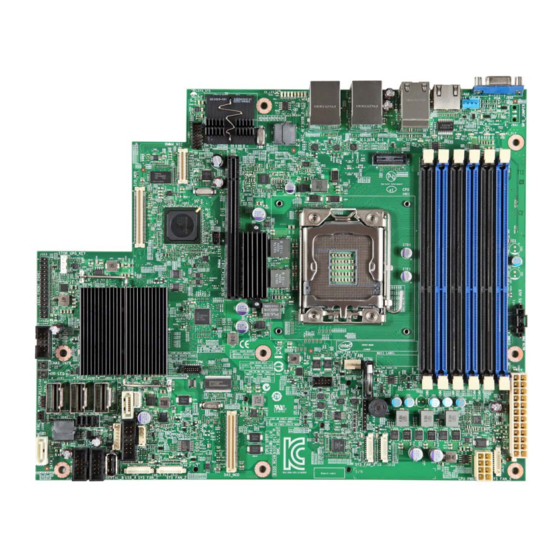
Overview Intel® Server Board S1400SP TPS Server Board Layout ® Figure 1. Intel Server Board S1400SP4 Layout Intel order number G64248-003 Revision 2.1... -
Page 17: Server Board Connector And Component Layout
Intel® Server Board S1400SP TPS Overview 2.2.1 Server Board Connector and Component Layout The following figures show the layout of the server board. ® Figure 2. Intel Server Board S1400SP Layout Figure 3. Jumper Block Identification Revision 2.1 Intel order number G64248-003... -
Page 18: Server Board Mechanical Drawings
Overview Intel® Server Board S1400SP TPS 2.2.2 Server Board Mechanical Drawings ® Figure 4. Intel Server Board S1400SP – Mounting Hole Locations (1 of 2) Intel order number G64248-003 Revision 2.1... -
Page 19: Figure 5. Intel Server Board S1400Sp - Mounting Hole Locations (2 Of 2)
Intel® Server Board S1400SP TPS Overview ® Figure 5. Intel Server Board S1400SP – Mounting Hole Locations (2 of 2) Revision 2.1 Intel order number G64248-003... -
Page 20: Figure 6. Intel Server Boards S1400Sp - Major Connector Pin-1 Locations (1 Of 2)
Overview Intel® Server Board S1400SP TPS ® Figure 6. Intel Server Boards S1400SP – Major Connector Pin-1 Locations (1 of 2) Intel order number G64248-003 Revision 2.1... -
Page 21: Figure 7. Intel Server Boards S1400Sp - Major Connector Pin-1 Locations (2 Of 2)
Intel® Server Board S1400SP TPS Overview ® Figure 7. Intel Server Boards S1400SP – Major Connector Pin-1 Locations (2 of 2) Revision 2.1 Intel order number G64248-003... -
Page 22: Figure 8. Intel Server Boards S1400Sp - Primary Side Keepout Zone
Overview Intel® Server Board S1400SP TPS ® Figure 8. Intel Server Boards S1400SP – Primary Side Keepout Zone Intel order number G64248-003 Revision 2.1... -
Page 23: Figure 9. Intel Server Boards S1400Sp - Primary Side Card Side Keepout Zone
Intel® Server Board S1400SP TPS Overview ® Figure 9. Intel Server Boards S1400SP – Primary Side Card Side Keepout Zone ® Figure 10. Intel Server Boards S1400SP – Primary Side Air Duct Keepout Zone Revision 2.1 Intel order number G64248-003... -
Page 24: Server Board Rear I/O Layout
Overview Intel® Server Board S1400SP TPS ® Figure 11. Intel Server Boards S1400SP – Second Side Keepout Zone 2.2.3 Server Board Rear I/O Layout The following drawings show the layout of the rear I/O components for the server board. ®... -
Page 25: Figure 13. Intel Server Boards S1400Sp4 Rear I/O Layout
Intel® Server Board S1400SP TPS Overview ® Figure 13. Intel Server Boards S1400SP4 Rear I/O Layout Revision 2.1 Intel order number G64248-003... -
Page 26: Functional Architecture
The architecture and design of the Intel Server Board S1400SP is based on the Intel C600 ® ® chipset family. The chipset is designed for systems based on the Intel Xeon processor in an ® ® FC-LGA 1356 Socket B2 package with Intel QuickPath Interconnect (Intel QPI). -
Page 27: Processor Socket Assembly
Intel® Server Board S1400SP TPS Functional Architecture ® ® ® Note: Previous generation Intel Xeon processors are not supported on the Intel server board described in this document. ® Visit the Intel website for a complete list of supported processors. 3.1.1... -
Page 28: Intel Quickpath Interconnect
Functional Architecture Intel® Server Board S1400SP TPS The following sections will provide an overview of the key processor features and functions that help to define the performance and architecture of the server board. Processor Feature Details: ® ® Up to 8 execution cores (Intel... -
Page 29: Integrated Memory Controller (Imc) And Memory Subsystem
Intel® Server Board S1400SP TPS Functional Architecture links to complete the connection between two components. This supports traffic in both directions simultaneously. To facilitate flexibility and longevity, the interconnect is defined as having five layers: Physical, Link, Routing, Transport, and Protocol. -
Page 30: Table 2. Udimm Support Guidelines
1333 1333 Notes: ® Supported DRAM Densities are 1Gb, 2Gb and 4Gb. Only 2Gb and 4Gb are validated by Intel Command Address Timing is 1N for 1DPC and 2N for 2DPC. Supported and Validated Supported but not Validated Table 3. RDIMM Support Guidelines... -
Page 31: Figure 16. Intel Server Board S1400Sp Dimm Slot Layout
Intel® Server Board S1400SP TPS Functional Architecture Notes: ® Supported DRAM Densities are 1Gb, 2Gb and 4Gb. Only 2Gb and 4Gb are validated by Intel Command Address Timing is 1N. Supported and Validated Supported but not Validated 3.2.2.2 Memory Slot Identification and Population Rules Note: Although mixed DIMM configurations may be functional, Intel only performs platform validation on systems that are configured with identical DIMMs installed. - Page 32 Mixing of Registered and Unbuffered DIMMs is not allowed per platform. ® Mixing of DDR3 voltages is not validated within a socket or across sockets by Intel . If 1.35V (DDR3L) and 1.50V (DDR3) DIMMs are mixed, the DIMMs will run at 1.50V.
- Page 33 Intel® Server Board S1400SP TPS Functional Architecture Note: Some server operating systems do not display the total physical memory installed. What is displayed is the amount of physical memory minus the approximate memory space used by system BIOS components. These BIOS components include, but are not limited to: 1.
- Page 34 Functional Architecture Intel® Server Board S1400SP TPS Rank Sparing Mode enhances the system’s RAS capability by “swapping out” failing ranks of DIMMs. Rank Sparing is strictly channel and rank oriented. Each memory channel is a Sparing Domain. For Rank Sparing to be available as a RAS option, there must be 2 or more single rank or dual rank DIMMs, or at least one quad rank DIMM installed on each memory channel.
- Page 35 Intel® Server Board S1400SP TPS Functional Architecture When Mirroring Mode is operational, the system treats Correctable Errors the same way as it would in Independent channel mode. There is a correctable error threshold. Correctable error counts accumulate by rank, and the first event is logged.
- Page 36 Functional Architecture Intel® Server Board S1400SP TPS 3.2.2.4.5 Single Device Data Correction (SDDC) SDDC – Single Device Data Correction is a technique by which data can be replaced by the IMC from an entire x4 DRAM device which is failing, using a combination of CRC plus parity.
-
Page 37: Processor Integrated I/O Module (Iio)
Intel® Server Board S1400SP TPS Functional Architecture 3.2.2.4.7 Demand Scrubbing for ECC Memory Demand scrubbing is the ability to write corrected data back to the memory once a correctable error is detected on a read transaction. This allows for correction of data in memory at detect, and decrease the chances of a second error on the same address accumulating to cause a multi-bit error (MBE) condition. -
Page 38: Figure 17. Functional Block Diagram Of Processor Iio Sub-System
IIO module. These include the Riser Card Slots, Network Interface, and ® connectors for the optional I/O modules and SAS Module. Features and functions of the Intel C600 Series chipset will be described in its own dedicated section. -
Page 39: Figure 18. Pci Express* Lane Mapping
Intel® Server Board S1400SP TPS Functional Architecture PCIe Port0/DMI2 B0,D0,F0 PCIe Port 1a PCIe Port 1b B0,D0,F1 ROC module conn PCIe Port 2a PCIe Port 2b CPU0 PCIe Port 2c PCIe Port 2d B0,D3,F0 PCIe Port 3a B0,D3,F1 IO module conn PCIe Port 3b PCIe Port 3c B0,D3,F1 Slot6 x16conn PCIe Port 3d Figure 18. PCI Express* Lane Mapping 3.2.3.2 Riser Card Support The server board includes one riser card slot labeled SLOT_6 (PCIe_x16). See the Technical ®... -
Page 40: Intel ® C600-A Chipset Functional Overview
® On the Intel Server Board S1400SP, two for S1400SP2 and four for S1400SP4 external 10/100/1000 Mb RJ45 Ethernet ports are provided. Each Ethernet port drives two LEDs located on each network interface connector. The LED at the right of the connector is the link/activity LED and indicates network connection when on, and transmit/receive activity when blinking. -
Page 41: Low Pin Count (Lpc) Interface
Intel® Server Board S1400SP TPS Functional Architecture Figure 20. Functional Block Diagram – Chipset Supported Features and Functions ® On the Intel Server Boards S1400SP, the chipset provides support for the following on-board functions: PCI Express* root ports ... -
Page 42: On-Board Serial Attached Scsi (Sas)/Serial Ata (Sata) Support And Options
The server board is capable of supporting additional chipset embedded SAS and RAID options ® from the SCU controller when configured with one of several available Intel RAID C600 Upgrade Keys. Upgrade keys install onto a 4-pin connector on the server board labeled STOR_UPG_KEY. - Page 43 ® or Intel ESRT2 8 ports SAS R0,1,10,5 or Intel ESRT2 SATA R0,1,10,5 Additional information for the on-board RAID features and functionality can be found in the Intel ® ® RAID Software Users Guide (Intel Document Number D29305). The system includes support for two embedded software RAID options: ®...
-
Page 44: Manageability
Functional Architecture Intel® Server Board S1400SP TPS ® o 4 and 8 Port SAS RAID 5 support provided with appropriate Intel RAID C600 Upgrade Key. Maximum drive support = Eight (with or without SAS expander option installed). Open Source Compliance = Binary Driver (includes Partial Source files) or Open Source ... -
Page 45: Integrated Baseboard Management Controller (Bmc) Overview
Intel® Server Board S1400SP TPS Functional Architecture ECC Error Reporting. When detecting an ECC error, the host controller has the ability to send one of several messages to the chipset. The host controller can instruct the chipset to generate SMI #, NMI, SERR#, or TCO interrupt. -
Page 46: Super I/O Controller
Functional Architecture Intel® Server Board S1400SP TPS Figure 23. Integrated BMC Hardware 3.4.1 Super I/O Controller The integrated super I/O controller provides support for the following features as implemented on the server board: Two Fully Functional Serial Ports, compatible with the 16C550 ... -
Page 47: Graphics Controller And Video Support
Intel® Server Board S1400SP TPS Functional Architecture 3.4.1.2 Wake-up Control The super I/O contains functionality that allows various events to power on and power off the system. 3.4.2 Graphics Controller and Video Support The integrated graphics controller provides support for the following features as implemented on... -
Page 48: Baseboard Management Controller
Functional Architecture Intel® Server Board S1400SP TPS Table 9. Video mode On-board Video Enabled Disabled Dual Monitor Video Enabled Shaded if on-board video is set to "Disabled" Disabled 3.4.3 Baseboard Management Controller The server board utilizes the following features of the embedded baseboard management controller. - Page 49 Intel® Server Board S1400SP TPS Functional Architecture Hardware Based Video Compression and Redirection Logic Supports both text and Graphics redirection Hardware assisted Video redirection using the Frame Processing Engine Direct interface to the Integrated Graphics Controller registers and Frame buffer ...
-
Page 50: System Security
System Security Intel® Server Board S1400SP TPS System Security BIOS Password Protection The BIOS uses passwords to prevent unauthorized tampering with the server setup. Passwords can restrict entry to the BIOS Setup, restrict use of the Boot Popup menu, and suppress automatic USB device reordering. -
Page 51: Trusted Platform Module (Tpm) Support
Intel® Server Board S1400SP TPS System Security In addition to restricting access to most Setup fields to viewing only when a User password is entered, defining a User password imposes restrictions on booting the system. In order to simply boot in the defined boot order, no password is required. However, the F6 Boot popup prompts for a password, and can only be used with the Administrator password. -
Page 52: Physical Presence
System Security Intel® Server Board S1400SP TPS Produces EFI and legacy interfaces to a TPM-enabled operating system for using TPM. Produces ACPI TPM device and methods to allow a TPM-enabled operating system to send TPM administrative command requests to the BIOS. -
Page 53: Figure 24. Setup Utility - Tpm Configuration Screen
4.2.3.1 Security Screen ® To enter the BIOS Setup, press the F2 function key during boot time when the OEM or Intel logo displays. The following message displays on the diagnostics screen and under the Quiet Boot logo screen: Press <F2> to enter setup When the Setup is entered, the Main screen displays. -
Page 54: Txt)
® attacks, Intel Trusted Execution Technology integrates new security features and capabilities ® into the processor, chipset and other platform components. When used in conjunction with Intel ® Virtualization Technology, Intel Trusted Execution Technology provides hardware-rooted trust for your virtual applications. - Page 55 Technology compatible measured launched environment (MLE). The MLE could consist of a ® virtual machine monitor, an OS or an application. In addition, Intel Trusted Execution Technology requires the system to include a TPM v1.2, as defined by the Trusted Computing Group TPM PC Client Specification, Revision 1.2.
-
Page 56: Technology Support
® attacks. Intel Trusted Execution Technology integrates new security features and capabilities ® into the processor, chipset and other platform components. When used in conjunction with Intel ® ® Virtualization Technology and Intel VT for Directed IO, with an active TPM, Intel Trusted Execution Technology provides hardware-rooted trust for your virtual applications. -
Page 57: Intel Intelligent Power Node Manager
Intel® Server Board S1400SP TPS Technology Support For more information on the DMAR table and the DRHD entry format, refer to the Intel ® Virtualization Technology for Directed I/O Architecture Specification. For more general ® information about VT-x, VT-d, and VT-c, a good reference is Enabling Intel Virtualization Technology Features and Benefits White Paper. -
Page 58: Hardware Requirements
PMBus*-compliant power supplies provide the capability to monitoring input power consumption, which is necessary to support NM. ® Below are the some of the applications of Intel Intelligent Power Node Manager technology. Platform Power Monitoring and Limiting: The ME/NM monitors platform power ... -
Page 59: Platform Management Functional Overview
This chapter provides a high level overview of the platform management features and functionality implemented on the server board. For more in depth and design level Platform Management information, please reference the BMC Core Firmware External Product ® Specification (EPS) and BIOS Core External Product Specification (EPS) for Intel Server ® ®... -
Page 60: Non Ipmi Features
Platform Management Functional Overview Intel® Server Board S1400SP TPS BMC self test: The BMC performs initialization and run-time self-tests and makes results available to external entities. See also the Intelligent Platform Management Interface Specification Second Generation v2.0. 6.1.2 Non IPMI Features... -
Page 61: New Manageability Features
Intel® Server Board S1400SP TPS Platform Management Functional Overview ® Intel Light-Guided Diagnostics Address Resolution Protocol (ARP): The BMC sends and responds to ARPs (supported on embedded NICs). Dynamic Host Configuration Protocol (DHCP): The BMC performs DHCP (supported on ... -
Page 62: Basic And Advanced Features
Platform Management Functional Overview Intel® Server Board S1400SP TPS Enhancements to fan speed control. DCMI 1.1 compliance (product-specific). Support for embedded web server UI in Basic Manageability feature set. Enhancements to embedded web server o Human-readable SEL... -
Page 63: Integrated Bmc Hardware: Emulex* Pilot Iii
Intel® Server Board S1400SP TPS Platform Management Functional Overview Feature Basic Advanced Acoustic Management Diagnostic Beep Code Support Power State Retention ARP/DHCP Support PECI Thermal Management Support E-mail Alerting Embedded Web Server SSH Support Integrated KVM Integrated Remote Media Redirection Lightweight Directory Access Protocol (LDAP) ®... -
Page 64: Advanced Configuration And Power Interface (Acpi)
Platform Management Functional Overview Intel® Server Board S1400SP TPS Port 80h snooping capability Secondary Service Processor (SSP), which provides the HW capability of offloading time critical processing tasks from the main ARM core. Emulex* Pilot III contains an integrated SIO, KVMS subsystem and graphics controller with the... -
Page 65: Bmc Watchdog
Intel® Server Board S1400SP TPS Platform Management Functional Overview External Signal Name or Source Capabilities Internal Subsystem Power state retention Implemented by means of BMC Turns power on when AC power returns internal logic Chipset Sleep S4/S5 signal (same as... -
Page 66: Sensor Monitoring
Platform Management Functional Overview Intel® Server Board S1400SP TPS FRB2 refers to the FRB algorithm that detects system failures during POST. The BIOS uses the BMC watchdog timer to back up its operation during POST. The BIOS configures the watchdog timer to indicate that the BIOS is using the timer for the FRB2 phase of the boot operation. -
Page 67: System Event Log (Sel)
6.11.1 Thermal and Acoustic Management The S1400SP offers multiple thermal and acoustic management features to maintain comprehensive thermal protection as well as intelligent fan speed control. The features can be adjusted in BIOS interface with path BIOS > Advanced > System Acoustic and Performance Configuration. -
Page 68: Setting Throttling Mode
Platform Management Functional Overview Intel® Server Board S1400SP TPS This capability requires the BMC to access temperature sensors on the individual memory DIMMs. Additionally, closed-loop thermal throttling is only supported with buffered DIMMs. 6.11.2 Setting Throttling Mode Select the most appropriate memory thermal throttling mechanism for memory sub-system from [Auto], [DCLTT], [SCLTT] and [SOLTT]. -
Page 69: Fan Profiles
® 2. Refer to the Intel ® Server System TPS for the board in Intel chassis thermal and acoustic management. 3. Refer to Fan Control Whitepaper for the board in 3rd party chassis fan speed control customization. -
Page 70: Figure 25. Fan Speed Control Process
Integrated BMC Temperature Sensor 3, 8 Global Aggregate Thermal Margin Sensors Note: ® 1. For fan speed control in Intel chassis 2. For fan speed control in third party chassis 3. Temperature margin from throttling threshold 4. Absolute temperature 5. PECI value 6. -
Page 71: Memory Thermal Throttling
Intel® Server Board S1400SP TPS Platform Management Functional Overview 6.11.9 Memory Thermal Throttling The server board provides support for system thermal management through open loop throttling (OLTT) and closed loop throttling (CLTT) of system memory. Normal system operation uses closed-loop thermal throttling (CLTT) and DIMM temperature monitoring as major factors in overall thermal and acoustics management. -
Page 72: User Model
Platform Management Functional Overview Intel® Server Board S1400SP TPS Table 16. Messaging Interfaces Channel ID Interface Supports Sessions Primary IPMB LAN 1 LAN 2 LAN 3 ® (Provided by the Intel Dedicated Server Management NIC) Reserved Secondary IPMB 8– 0Dh Reserved –... - Page 73 Intel® Server Board S1400SP TPS Platform Management Functional Overview See the Intelligent Platform Management Interface Specification Second Generation v2.0 for details about the IPMI-over-LAN protocol. Run-time determination of LAN channel capabilities can be determined by both standard IPMI defined mechanisms.
- Page 74 Platform Management Functional Overview Intel® Server Board S1400SP TPS 6.12.3.2.3 Concurrent Server Management Use of Multiple Ethernet Controllers The BMC FW supports concurrent OOB LAN management sessions for the following combination: 2 on-board NIC ports 1 on-board NIC and the optional dedicated RMM4 add-in management NIC.
- Page 75 Intel® Server Board S1400SP TPS Platform Management Functional Overview BMC LAN 3 (Dedicated NIC) ----- 1000Mb 6.12.3.3 IPV6 Support In addition to IPv4, the server board has support for IPv6 for manageability channels. Configuration of IPv6 is provided by extensions to the IPMI Set and Get LAN Configuration Parameters commands as well as through a Web Console IPv6 configuration web page.
- Page 76 Platform Management Functional Overview Intel® Server Board S1400SP TPS The LAN Failover feature applies only to BMC LAN traffic. It bonds all available Ethernet devices but only one is active at a time. When enabled, If the active connection’s leash is lost, one of the secondary connections is automatically configured so that it has the same IP address.
- Page 77 Intel® Server Board S1400SP TPS Platform Management Functional Overview When changing from DHCP to Static configuration, the initial values of these three parameters will be equivalent to the existing DHCP-set parameters. Additionally, the BMC observes the following network safety precautions: 1.
-
Page 78: Address Resolution Protocol (Arp)
Platform Management Functional Overview Intel® Server Board S1400SP TPS such circumstances has no effect, and the BMC returns error code 0xD5, “Cannot Execute command. Command, or request parameter(s) are not supported in present state.” 6.12.3.6 DHCP BMC Hostname The BMC allows setting a DHCP Hostname using the Set/Get LAN Configuration Parameters command. -
Page 79: Secure Shell (Ssh)
Intel® Server Board S1400SP TPS Platform Management Functional Overview members of the VLAN will be isolated from any other network traffic. Please note that VLAN does not change the behavior of the host network setting, it only affects the BMC LAN communication. -
Page 80: Platform Event Filter (Pef)
Platform Management Functional Overview Intel® Server Board S1400SP TPS Activating SOL: This command is not accepted by the BMC. It is sent by the BMC when SOL is activated to notify a remote client of the switch to SOL. -
Page 81: Alert Policy Table
Intel® Server Board S1400SP TPS Platform Management Functional Overview the traps is provided with the BMC firmware to facilitate interpretation of the traps by external software. The format of the MIB file is covered under RFC 2578. 6.12.11 Alert Policy Table Associated with each PEF entry is an alert policy that determines which IPMI channel the alert is to be sent. -
Page 82: Embedded Web Server
Platform Management Functional Overview Intel® Server Board S1400SP TPS The embedded web server is supported over any system NIC port that is enabled for server management capabilities. 6.12.13 Embedded Web Server BMC Base manageability provides an embedded web server and an OEM-customizable web GUI which exposes the manageability features of the BMC base feature set. -
Page 83: Virtual Front Panel
Embedded Platform Debug feature - Allow the user to initiate a “diagnostic dump” to a ® file that can be sent to Intel for debug purposes. Virtual Front Panel. The Virtual Front Panel provides the same functionality as the local ... -
Page 84: Embedded Platform Debug
The files are compressed, encrypted, and password protected. The file is not meant to be ® viewable by the end user but rather to provide additional debugging capability to an Intel support engineer. A list of data that may be captured using this feature includes but is not limited to: ... -
Page 85: Table 18. Diagnostic Data
The platform debug feature provides a means to capture this ® data for each installed power supply. The data can be analyzed by Intel failure analysis and possibly provided to the power supply vendor as well. The BMC gets this data from the power supplies from PMBus* manufacturer-specific commands. -
Page 86: Data Center Management Interface (Dcmi)
Platform Management Functional Overview Intel® Server Board S1400SP TPS Category Data Human-readable sensor listing External BIOS Data BIOS configuration settings POST codes for the two most recent boots System Data SMBIOS table for the current boot 256 bytes of PCI config data for each PCI device Memory Map (EFI and Legacy) for current boot Table 19. -
Page 87: Advanced Management Feature Support (Rmm4)
Advanced Management Feature Support (RMM4) The integrated baseboard management controller has support for advanced management ® features which are enabled when an optional Intel Remote Management Module 4 (RMM4) is installed. RMM4 is comprised of two boards – RMM4 lite and the optional Dedicated Server Management NIC (DMN). -
Page 88: Keyboard, Video, Mouse (Kvm) Redirection
Advanced Management Feature Support (RMM4) Intel® Server Board S1400SP TPS ® Figure 27. Intel RMM4 Dedicated Management NIC Installation Table 21. Enabling Advanced Management Features Manageability Hardware Benefits ® Intel Integrated BMC Comprehensive IPMI based base manageability features. ® Intel Remote Management Module 4 –... -
Page 89: Remote Console
Intel® Server Board S1400SP TPS Advanced Management Feature Support (RMM4) KVM redirection console support the following keyboard layouts: English, Dutch, French, German, Italian, Russian, and Spanish. KVM redirection includes a “soft keyboard” function. The “soft keyboard” is used to simulate an entire keyboard that is connected to the remote system. -
Page 90: Security
Advanced Management Feature Support (RMM4) Intel® Server Board S1400SP TPS For the best possible KVM performance, a 2Mb/sec link or higher is recommended. The redirection of KVM over IP is performed in parallel with the local KVM without affecting the local KVM operation. -
Page 91: Availability
Intel® Server Board S1400SP TPS Advanced Management Feature Support (RMM4) The media redirection feature supports multiple encryption algorithms, including RC4 and AES. The actual algorithm that is used is negotiated with the client based on the client’s capabilities. ... -
Page 92: On-Board Connector/Header Overview
On-board Connector/Header Overview Intel® Server Board S1400SP TPS On-board Connector/Header Overview The following section provides detailed information regarding all connectors, headers, and jumpers on the server boards. Board Connector Information The following table lists all connector types available on the board and the corresponding preference designators printed on the silkscreen. -
Page 93: Power Connectors
Intel® Server Board S1400SP TPS On-board Connector/Header Overview Connector Quantity Reference Designators Connector Type Pin Count HDD LED J1G2 Header SATA_0: J2H3 SATA Connector SATA_1: J1J1 SCU_0: J1H1 Mini-SAS Connector SCU_1: J1H2 Mini-SATA J2H1 Connector HSBP_I2C J2H2 Header J2H8 Header... -
Page 94: Front Panel Headers And Connectors
8.3.1 Front Panel Support ® The server board provides a 30-pin front panel connector (J1C3) for use with Intel and third- party chassis. The 30-pin connector consists of a 24-pin SSI compatible front panel connector and a 4-pin connector to support optional NIC 3/4 LEDs. The 24-pin SSI front panel connector provides various front panel features including: ... -
Page 95: Table 27. Power/Sleep Led Functional States
Intel® Server Board S1400SP TPS On-board Connector/Header Overview Signal Description Pin# Pin# Signal Description P3V3 FP_LED_STATUS_GREEN_R_N LED_HDD_ACTIVITY_R_N FP_LED_STATUS_AMBER_R_N FP_PWR_BTN_N LED _NIC_LINK0_ACT_FP_N GROUND LED _NIC_LINK0_LNKUP_FP_N FP_RST_BTN_R_N SMB_SENSOR_3V3STBY_DATA_R0 GROUND SMB_SENSOR_3V3STBY_CLK FP_ID_BTN_R_N FP_CHASSIS_INTRUSION PU_FM_SIO_TEMP_SENSOR LED_NIC_LINK1_ACT_FP_N FP_NMI_BTN_R_N LED_NIC_LINK1_LNKUP_FP_N LED_NIC_LINK2_ACT_FP_N LED_NIC_LINK3_ACT_FP_N LED_NIC_LINK2_LNKUP_FP_N LED_NIC_LINK3_LNKUP_FP_N 8.3.1.1 Power/Sleep Button and LED Support Pressing the Power button will toggle the system power on and off. -
Page 96: Front Panel Usb Connector
On-board Connector/Header Overview Intel® Server Board S1400SP TPS The following actions cause the BMC to generate an NMI pulse: Receiving a Chassis Control command to pulse the diagnostic interrupt. This command does not cause an event to be logged in the SEL. -
Page 97: Intel ® Local Control Panel Connector
Intel® Server Board S1400SP TPS On-board Connector/Header Overview Table 29. Front Panel USB Connector Pin-out Signal Description Pin# Pin# Signal Description P5V_USB_FP P5V_USB_FP USB2_P11_F_DN USB2_P13_F_DN USB2_P11_F_DP USB2_P13_F_DP GROUND GROUND TP_USB2_FP_10 8.3.3 Intel Local Control Panel Connector ® The server board includes a 7-pin connector that is used when the system is configured with the ®... -
Page 98: Fan Connectors
On-board Connector/Header Overview Intel® Server Board S1400SP TPS transfer rates of up to 3Gb/s. The connector labeled “SCU_1” is only enabled when an optional ® 8-port SAS or SATA Intel RAID C600 Upgrade Key is installed. See Table 7 for a complete list of supported storage upgrade keys. -
Page 99: Serial Port Connector
Intel® Server Board S1400SP TPS On-board Connector/Header Overview Table 33. SSI 4-pin Fan Header Pin-out Signal Name Type Description Ground Ground is the power supply ground Power Power supply 12 V Fan Tach FAN_TACH signal is connected to the BMC to monitor the fan speed... -
Page 100: System Management Headers
Intel Remote Management Module 4 or Intel Remote Management Module 4 Lite. This server board does not support third-party management cards. ® Note: This connector is not compatible with the previous generation Intel Remote Management ® Modules (Intel RMM/RMM2/RMM3). -
Page 101: Hsbp Header
Intel® Server Board S1400SP TPS On-board Connector/Header Overview Signal Name Signal Name P3V3 RST_IBMC_NIC_N CLK_33M_TPM_CONN LPC_LAD<3> LPC_LAD<2> 8.7.3 HSBP Header Table 39. HSBP_ I C Header Pin-out Signal Name SMB_HSBP_3V3STBY_DATA SMB_HSBP_3V3STBY_CLK 8.7.4 SGPIO Header Table 40. SGPIO Header Pin-out Signal Name... -
Page 102: Usb Connector
On-board Connector/Header Overview Intel® Server Board S1400SP TPS Table 42. RJ-45 10/100/1000 NIC Connector Pin-out Signal Name P1V8_NIC NIC_A_MDI3P NIC_A_MDI3N NIC_A_MDI2P NIC_A_MDI2N NIC_A_MDI1P NIC_A_MDI1N NIC_A_MDI0P NIC_A_MDI0N NIC_LINKA_1000_N (LED NIC_LINKA_100_N (LED) NIC_ACT_LED_N NIC_LINK_LED_N 8.8.3 USB Connector The following table details the pin-out of the external USB connectors found on the back edge of the server boards. -
Page 103: Other Connectors And Headers
Intel® Server Board S1400SP TPS On-board Connector/Header Overview Table 45. Internal Type-A USB Connector Pin-out Signal Description Pin# P5V_USB_INT USB2_P2_F_DN USB2_P2_F_DP GROUND Other Connectors and Headers The server board includes a 2-pin chassis intrusion header which can be used when the chassis is configured with a chassis intrusion switch. -
Page 104: Jumper Blocks
Jumper Blocks Intel® Server Board S1400SP TPS Jumper Blocks The server board has several 3-pin jumper blocks that can be used to configure, protect, or recover specific features of the server boards. The following symbol identifies Pin 1 on each jumper block on the silkscreen: ▼... -
Page 105: Bios Recovery Jumper
BIOS from one version to another. The following steps demonstrate the BIOS recovery process: ® 1. After downloading the latest System Update Package (SUP) from the Intel website, copy the following files to the root directory of a USB media device: IPMI.EFI... -
Page 106: Password Clear Jumper Block
Jumper Blocks Intel® Server Board S1400SP TPS Note: System Update and Recovery files are included in the System Update Packages (SUP) ® posted to Intel ’s website. 1. Turn off the system and remove power cords. 2. Move the ME FRC UPD Jumper from the default (pins 1 and 2) operating position to the Force Update position (pins 2 and 3). -
Page 107: Bmc Force Update Jumper Block
Intel® Server Board S1400SP TPS Jumper Blocks Note: BIOS Error Manager should report a 5220 error code (BIOS Settings reset to default settings) BMC Force Update Jumper Block The BMC Force Update jumper is used to put the BMC in Boot Recovery mode for a low-level update. -
Page 108: Intel Light Guided Diagnostics
Intel® Light Guided Diagnostics Intel® Server Board S1400SP TPS 10. Intel Light Guided Diagnostics ® The server board includes several on-board LED indicators to aid troubleshooting various board level faults. The following diagram shows the location for each. Figure 29. On-Board Diagnostic LED Placement Intel order number G64248-003 Revision 2.1... -
Page 109: 10.1 System Id Led
Intel® Server Board S1400SP TPS Intel® Light Guided Diagnostics Figure 30. Memory Slot Fault LED Locations 10.1 System ID LED The server board includes a blue system ID LED which is used to visually identify a specific server installed among many other similar servers. There are two options available for illuminating the System ID LED: 1. -
Page 110: Table 49. System Status Led State Definitions
Intel® Light Guided Diagnostics Intel® Server Board S1400SP TPS Table 49. System Status LED State Definitions Color State Criticality Description Green Solid on Indicates that the System Status is ‗Healthy‘. The system is not exhibiting any errors. AC power is present and BMC has booted and manageability functionality is up and running. -
Page 111: 10.3 Bmc Boot/Reset Status Led Indicators
Intel® Server Board S1400SP TPS Intel® Light Guided Diagnostics Amber Solid on Critical, non- Fatal alarm – system has failed or shutdown: recoverable 1. CPU CATERR signal asserted 2. MSID mismatch detected (CATERR also asserts for this case). 3. CPU 1 is missing 4. -
Page 112: 10.5 5 Volt Stand-By Present Led
Intel® Light Guided Diagnostics Intel® Server Board S1400SP TPS condition during the POST process. The diagnostic LEDs can be used to identify the last POST process to be executed. See Appendix D for a complete description of how these LEDs are read, and for a list of all supported POST codes. -
Page 113: 11. Environmental Limits Specification
Intel Corporation cannot be held responsible if components fail or the server board does not operate correctly when used outside any of its published operating or non-operating limits. -
Page 114: 11.2 Mtbf
Intel Corporation cannot be held responsible, if components fail or the server board does not operate correctly when used outside any of their published operating or non-operating limits. -
Page 115: 12. Server Board Power Distribution
Intel® Server Board S1400SP TPS Server Board Power Distribution 12. Server Board Power Distribution ® This section provides power supply design guidelines for a system using the Intel Server Board S1400SP. The following diagram shows the power distribution implemented on this server board. -
Page 116: 12.2 Power Supply Output Requirements
Server Board Power Distribution Intel® Server Board S1400SP TPS ® ® Table 53. Intel Xeon Processor TDP Guidelines TDP Power Max Tcase Icc Max 95 W 78°C 130 A 75°C 80W (1 71°C socket) 70°C 110A 67°C 65°C 12.2 Power Supply Output Requirements This section is for reference purposes only. -
Page 117: Capacitive Loading
Intel® Server Board S1400SP TPS Server Board Power Distribution 50Hz and 5kHz at duty cycles ranging from 10%-90%. The load transient repetition rate is only a test specification. The step load may occur anywhere within the MIN load to the MAX load conditions. -
Page 118: Soft Starting
Server Board Power Distribution Intel® Server Board S1400SP TPS The measurement shall be made across a 100Ω resistor between each of DC outputs, including ground at the DC power connector and chassis ground (power subsystem enclosure). The test set-up shall use a FET probe such as Tektronix* model P6046 or equivalent. -
Page 119: Figure 32. Output Voltage Timing
Intel® Server Board S1400SP TPS Server Board Power Distribution Vout Vout vout_off vout rise vout_on Figure 32. Output Voltage Timing Table 60. Turn On/Off Timing Item Description UNITS Delay from AC being applied to 5VSB being within regulation. 1500 sb_on_delay Delay from AC being applied to all output voltages being within regulation. -
Page 120: Residual Voltage Immunity In Stand-By Mode
Server Board Power Distribution Intel® Server Board S1400SP TPS AC Input vout_holdup Vout pwok_low AC_on_delay pwok_off sb_on_delay pwok_on pwok_off sb_on_delay pwok_on PWOK pson_pwok pwok_holdup 5VSB sb_vout 5VSB holdup pson_on_delay PSON AC turn on/off cycle PSON turn on/off cycle Figure 33. Turn On/Off Timing (Power Supply Signals) 12.2.14... -
Page 121: Appendix A: Integration And Usage Tips
Mixing of RDIMMs and UDIMMs is not supported. ® ® The Intel RMM4/RMM4 Lite connectors are not compatible with the previous Intel Remote Management Modules Clear CMOS with the AC power cord plugged in. Removing AC power before performing ... -
Page 122: Appendix B: Integrated Bmc Sensor Tables
Appendix B: Integrated BMC Sensor Tables Intel® Server Board S1400SP TPS Appendix B: Integrated BMC Sensor Tables This appendix lists the sensor identification numbers and information about the sensor type, name, supported thresholds, assertion and de-assertion information, and a brief description of the sensor purpose. - Page 123 Intel® Server Board S1400SP TPS Appendix B: Integrated BMC Sensor Tables Rearm Sensors The rearm is a request for the event status of a sensor to be rechecked and updated upon a transition between good and bad states. You can rearm the sensors manually or automatically.
-
Page 124: Table 61. Integrated Bmc Core Sensors
Appendix B: Integrated BMC Sensor Tables Intel® Server Board S1400SP TPS Table 61. Integrated BMC Core Sensors Full Sensor Name Sensor # Platform Sensor Type Event/Reading Event Offset Triggers Contrib. To Assert/De- Readable Event Rearm Standby (Sensor name in Applicability... - Page 125 Intel® Server Board S1400SP TPS Appendix B: Integrated BMC Sensor Tables Full Sensor Name Sensor # Platform Sensor Type Event/Reading Event Offset Triggers Contrib. To Assert/De- Readable Event Rearm Standby (Sensor name in Applicability Type System assert Value/ Data SDR)
- Page 126 Appendix B: Integrated BMC Sensor Tables Intel® Server Board S1400SP TPS Full Sensor Name Sensor # Platform Sensor Type Event/Reading Event Offset Triggers Contrib. To Assert/De- Readable Event Rearm Standby (Sensor name in Applicability Type System assert Value/ Data SDR)
- Page 127 Intel® Server Board S1400SP TPS Appendix B: Integrated BMC Sensor Tables Full Sensor Name Sensor # Platform Sensor Type Event/Reading Event Offset Triggers Contrib. To Assert/De- Readable Event Rearm Standby (Sensor name in Applicability Type System assert Value/ Data SDR)
- Page 128 Appendix B: Integrated BMC Sensor Tables Intel® Server Board S1400SP TPS Full Sensor Name Sensor # Platform Sensor Type Event/Reading Event Offset Triggers Contrib. To Assert/De- Readable Event Rearm Standby (Sensor name in Applicability Type System assert Value/ Data SDR)
- Page 129 Intel® Server Board S1400SP TPS Appendix B: Integrated BMC Sensor Tables Full Sensor Name Sensor # Platform Sensor Type Event/Reading Event Offset Triggers Contrib. To Assert/De- Readable Event Rearm Standby (Sensor name in Applicability Type System assert Value/ Data SDR)
- Page 130 Appendix B: Integrated BMC Sensor Tables Intel® Server Board S1400SP TPS Full Sensor Name Sensor # Platform Sensor Type Event/Reading Event Offset Triggers Contrib. To Assert/De- Readable Event Rearm Standby (Sensor name in Applicability Type System assert Value/ Data SDR)
- Page 131 Intel® Server Board S1400SP TPS Appendix B: Integrated BMC Sensor Tables Full Sensor Name Sensor # Platform Sensor Type Event/Reading Event Offset Triggers Contrib. To Assert/De- Readable Event Rearm Standby (Sensor name in Applicability Type System assert Value/ Data SDR)
- Page 132 Appendix B: Integrated BMC Sensor Tables Intel® Server Board S1400SP TPS Full Sensor Name Sensor # Platform Sensor Type Event/Reading Event Offset Triggers Contrib. To Assert/De- Readable Event Rearm Standby (Sensor name in Applicability Type System assert Value/ Data SDR)
- Page 133 Intel® Server Board S1400SP TPS Appendix B: Integrated BMC Sensor Tables Full Sensor Name Sensor # Platform Sensor Type Event/Reading Event Offset Triggers Contrib. To Assert/De- Readable Event Rearm Standby (Sensor name in Applicability Type System assert Value/ Data SDR)
- Page 134 Appendix B: Integrated BMC Sensor Tables Intel® Server Board S1400SP TPS Full Sensor Name Sensor # Platform Sensor Type Event/Reading Event Offset Triggers Contrib. To Assert/De- Readable Event Rearm Standby (Sensor name in Applicability Type System assert Value/ Data SDR)
- Page 135 Intel® Server Board S1400SP TPS Appendix B: Integrated BMC Sensor Tables Full Sensor Name Sensor # Platform Sensor Type Event/Reading Event Offset Triggers Contrib. To Assert/De- Readable Event Rearm Standby (Sensor name in Applicability Type System assert Value/ Data SDR)
- Page 136 Appendix B: Integrated BMC Sensor Tables Intel® Server Board S1400SP TPS Full Sensor Name Sensor # Platform Sensor Type Event/Reading Event Offset Triggers Contrib. To Assert/De- Readable Event Rearm Standby (Sensor name in Applicability Type System assert Value/ Data SDR)
- Page 137 Intel® Server Board S1400SP TPS Appendix B: Integrated BMC Sensor Tables Full Sensor Name Sensor # Platform Sensor Type Event/Reading Event Offset Triggers Contrib. To Assert/De- Readable Event Rearm Standby (Sensor name in Applicability Type System assert Value/ Data SDR)
- Page 138 Appendix B: Integrated BMC Sensor Tables Intel® Server Board S1400SP TPS Full Sensor Name Sensor # Platform Sensor Type Event/Reading Event Offset Triggers Contrib. To Assert/De- Readable Event Rearm Standby (Sensor name in Applicability Type System assert Value/ Data SDR)
- Page 139 Intel® Server Board S1400SP TPS Appendix B: Integrated BMC Sensor Tables Full Sensor Name Sensor # Platform Sensor Type Event/Reading Event Offset Triggers Contrib. To Assert/De- Readable Event Rearm Standby (Sensor name in Applicability Type System assert Value/ Data SDR)
- Page 140 Appendix B: Integrated BMC Sensor Tables Intel® Server Board S1400SP TPS Full Sensor Name Sensor # Platform Sensor Type Event/Reading Event Offset Triggers Contrib. To Assert/De- Readable Event Rearm Standby (Sensor name in Applicability Type System assert Value/ Data SDR)
- Page 141 Intel® Server Board S1400SP TPS Appendix B: Integrated BMC Sensor Tables Full Sensor Name Sensor # Platform Sensor Type Event/Reading Event Offset Triggers Contrib. To Assert/De- Readable Event Rearm Standby (Sensor name in Applicability Type System assert Value/ Data SDR)
- Page 142 Appendix B: Integrated BMC Sensor Tables Intel® Server Board S1400SP TPS Full Sensor Name Sensor # Platform Sensor Type Event/Reading Event Offset Triggers Contrib. To Assert/De- Readable Event Rearm Standby (Sensor name in Applicability Type System assert Value/ Data SDR)
- Page 143 Intel® Server Board S1400SP TPS Appendix B: Integrated BMC Sensor Tables Full Sensor Name Sensor # Platform Sensor Type Event/Reading Event Offset Triggers Contrib. To Assert/De- Readable Event Rearm Standby (Sensor name in Applicability Type System assert Value/ Data SDR)
- Page 144 Appendix B: Integrated BMC Sensor Tables Intel® Server Board S1400SP TPS Full Sensor Name Sensor # Platform Sensor Type Event/Reading Event Offset Triggers Contrib. To Assert/De- Readable Event Rearm Standby (Sensor name in Applicability Type System assert Value/ Data SDR)
- Page 145 Intel® Server Board S1400SP TPS Appendix B: Integrated BMC Sensor Tables Full Sensor Name Sensor # Platform Sensor Type Event/Reading Event Offset Triggers Contrib. To Assert/De- Readable Event Rearm Standby (Sensor name in Applicability Type System assert Value/ Data SDR)
-
Page 146: Appendix C: Post Code Diagnostic Led Decoder
Appendix C: POST Code Diagnostic LED Decoder Intel® Server Board S1400SP TPS Appendix C: POST Code Diagnostic LED Decoder As an aid to assist in trouble shooting a system hang that occurs during a system’s Power-On Self Test (POST) process, the server board includes a bank of eight POST Code Diagnostic LEDs on the back edge of the server board. -
Page 147: Table 62. Post Progress Code Led Example
Intel® Server Board S1400SP TPS Appendix C: POST Code Diagnostic LED Decoder Table 62. POST Progress Code LED Example Upper Nibble AMBER LEDs Lower Nibble GREEN LEDs LEDs LED #7 LED #6 LED #5 LED #4 LED #3 LED #2... - Page 148 Appendix C: POST Code Diagnostic LED Decoder Intel® Server Board S1400SP TPS Diagnostic LED Decoder 1 = LED On, 0 = LED Off Checkpoint Upper Nibble Lower Nibble 4h 2h 1h 8h 4h 2h LED # #7 #6 #5 #4 #3 #2 #1 #0...
-
Page 149: Table 64. Mrc Progress Codes
Intel® Server Board S1400SP TPS Appendix C: POST Code Diagnostic LED Decoder POST Memory Initialization MRC Diagnostic Codes There are two types of POST Diagnostic Codes displayed by the MRC during memory initialization; Progress Codes and Fatal Error Codes. The MRC Progress Codes are displayed to the Diagnostic LEDs that show the execution point in the MRC operational path at each step. -
Page 150: Table 65. Post Progress Led Codes
Appendix C: POST Code Diagnostic LED Decoder Intel® Server Board S1400SP TPS Table 65. POST Progress LED Codes Diagnostic LED Decoder 1 = LED On, 0 = LED Off Checkpoint Upper Nibble Lower Nibble Description #7 #6 #5 #4 #3 #2 #1 #0... -
Page 151: Appendix D: Post Code Errors
® Note: The POST error codes in the following table are common to all current generation Intel server platforms. Features present on a given server board/system will determine which of the listed error codes are supported. -
Page 152: Table 66. Post Error Codes And Messages
Processor core/thread count mismatch detected Fatal 0192 Processor cache size mismatch detected Fatal 0194 Processor family mismatch detected Fatal 0195 Processor Intel(R) QPI link frequencies unable to synchronize Fatal 0196 Processor model mismatch detected Fatal 0197 Processor frequencies unable to synchronize Fatal 5220... - Page 153 Intel® Server Board S1400SP TPS Appendix D: POST Code Errors Error Code Error Message Response 852D DIMM_E2 failed test/initialization Major 852E DIMM_E3 failed test/initialization Major 852F DIMM_F1 failed test/initialization Major 8530 DIMM_F2 failed test/initialization Major 8531 DIMM_F3 failed test/initialization Major...
- Page 154 Appendix D: POST Code Errors Intel® Server Board S1400SP TPS Error Code Error Message Response 8563 DIMM_B1 encountered a Serial Presence Detection (SPD) failure Major 8564 DIMM_B2 encountered a Serial Presence Detection (SPD) failure Major 8565 DIMM_B3 encountered a Serial Presence Detection (SPD) failure...
-
Page 155: Table 67. Post Error Beep Codes
Intel® Server Board S1400SP TPS Appendix D: POST Code Errors Error Code Error Message Response 85DB DIMM_O2 disabled Major 85DC DIMM_O3 disabled Major 85DD DIMM_P1 disabled Major 85DE DIMM_P2 disabled Major 85DF DIMM_P3 disabled Major 85E0 DIMM_K3 encountered a Serial Presence Detection (SPD) failure... -
Page 156: Table 68. Integrated Bmc Beep Codes
® not sounded continuously. Codes that are common across all Intel server boards and systems that use same generation chipset are listed in the following table. Each digit in the code is represented by a sequence of beeps whose count is equal to the digit. -
Page 157: Appendix E: Supported Intel Server Chassis
Server Chassis ® ® The Intel Server System R1000SP product family is comprised of several available 1U rack ® mount server systems that are all integrated with an Intel Server Board S1400SP. Server System Integrated Server Board ® ® Intel... - Page 158 ® Quad port 1 GbE based on Intel Ethernet Controller I350 – AXX4P1GBPWLIOM ® Dual RJ-45 port 10GBase-T I/O Module based on Intel Ethernet Controller x540 – I/O Module AXX10GBTWLIOM Accessory Options ®...
-
Page 159: Glossary
Intel® Server Board S1400SP TPS Glossary Glossary This appendix contains important terms used in the preceding chapters. For ease of use, numeric entries are listed first (for example, “82460GX”) with alpha entries following (for example, “AGP 4x”). Acronyms are then entered in their respective place, with non-acronyms following. - Page 160 Glossary Intel® Server Board S1400SP TPS Term Definition Inter-integrated circuit bus ® Intel architecture Input buffer I/O controller hub IERR Internal error INIT Initialization signal IPMB Intelligent Platform Management Bus IPMI Intelligent Platform Management Interface In-target probe Keyboard controller style...
- Page 161 Intel® Server Board S1400SP TPS Glossary Term Definition Read-only memory Real-time clock System Control Interrupt. A system interrupt used by hardware to notify the operating system of ACPI events. Sensor data record SDRAM Synchronous dynamic random access memory System event log...
-
Page 162: Reference Documents
Advanced Configuration and Power Interface Specification, Revision 3.0, http://www.acpi.info/. Intelligent Platform Management Bus Communications Protocol Specification, Version 1.0. 1998. Intel Corporation, Hewlett-Packard* Company, NEC* Corporation, Dell* Computer Corporation. Intelligent Platform Management Interface Specification, Version 2.0. 2004. Intel Corporation, Hewlett-Packard* Company, NEC* Corporation, Dell* Computer Corporation.