
Related Manuals for HYOSUNG GT 650 EFI


Summary of Contents for HYOSUNG GT 650 EFI
- Page 1 WARNING This owner’s manual contains important safety information. Please read it carefully.
- Page 2 This manual should be considered a permanent part of the motorcycle and should remain with the motorcycle when resold or otherwise transferred to a new owner or operator. The manual contains important safety informa- tion and instructions which should be read carefully before operating the motorcycle.
- Page 3 (Standard type)
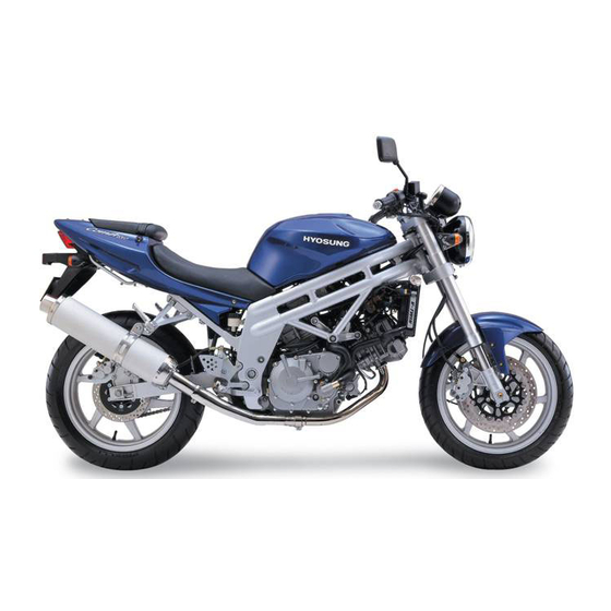
- Page 4 (Sports type)
- Page 5 Motorcycling Hyosung reserves the right to make is one of the most exhilarating sports and changes at any time. insure you to enjoy riding and you should...
- Page 6 Information following these signal words mance from your new motorcycle. should be carefully reviewed. Hyosung parts are manufactured of high quality materials, and manufactured parts WARNING are finished to close tolerances. Proper break-in operation allows the machined sur-...
- Page 7 WARNING Noise Control System (muffler assembly) TAMPERING WITH NOISE CONTROL SYSTEM PROHIBITED Owners are warned that the law may prohibit : (a) The removal or rendering inoperative by any person other than for the purpose of maintenance, repair or replacement, of any device or ele- ment of design incorporated into any new vehicle for the purpose of noise control prior to its any sale or delivery to the ultimate purchaser or while it is in use ;...
- Page 8 ● ● Observe periodic maintenance riders. Keep the owner’s manual in requirements your authorized the owner’s manual storage compart- HYOSUNG dealer is trained and ment located under the seat. equipped to perform this service. ● ● Before the rider’s first use of the ●...
- Page 9 WARNING WARNING Keep both hands on the handgrips at all are equipped with the side stand ignition interlock system. times when riding. Removing your If the transmission is in neutral or side hands from the handgrips reduces your stand up, you can only start the engine ability to control the motorcycle, and pulling the clutch lever.
- Page 10 ◉ ◉ FAMILIARIZE YOURSELF WITH WARNING THE MOTORCYCLE Do not operate the ignition switch in the WARNING “OFF” or “LOCK” position or the engine stop switch in the “ ” position Your riding skill and mechanical knowl- while driving at one’s pleasure. edge from the foundation for safe riding practices.
- Page 11 2. Inspect for proper ground clearance can lead to unsafe operating conditions. It and bank angle. An improperly mount- is not possible for Hyosung to test each accessory on the market or combinations ed load could critically reduce these two safety factors. Also determine that of all the available accessories, however, the “load”...
- Page 12 This limits the freedom of movement of the rider and may limit his or her control ability. 6. Additional electrical accessories may damage the existing electrical system. Severe overloads may damage the wiring harness or create a dangerous situation due to the loss of electrical power during the operation of the motorcycle.
- Page 13 TABLE OF CONTENTS 1. SERIAL NUMBER LOCATION ∙∙∙∙∙∙∙∙∙∙∙∙∙∙∙∙ 2. FUEL, ENGINE OIL AND COOLANT RECOMMENDATION ∙∙ FUEL ENGINE OIL ENGINE COOLANT SOLUTION 3. NAMES OF EACH PARTS [ ∙∙∙∙∙∙∙∙∙∙ 4. NAMES OF EACH PARTS [ ∙ (Standard type) 5. NAMES OF EACH PARTS [ ∙∙...
- Page 14 RIDING ON HILLS STOPPING AND PARKING 10. BREAK-IN ∙∙∙∙∙∙∙∙∙∙∙∙∙∙∙∙∙∙∙∙∙∙∙∙∙∙ 11. INSPECTION BEFORE RIDING ∙∙∙∙∙∙∙∙∙∙∙∙∙∙∙ 12. PERIODIC MAINTENANCE ∙∙∙∙∙∙∙∙∙∙∙∙∙∙∙∙∙ 13. INSPECTION AND MAINTENANCE ∙∙∙∙∙∙∙∙∙∙∙∙∙ TOOL FUEL HOSE ENGINE OIL GASOLINE ENGINE COOLANT RADIATOR RADIATOR HOSE RUBBER CAP OF CABLES EXHAUST PIPE AND MUFFLER FRONT FORK REAR SHOCK ABSORBER BATTERY...
- Page 15 Please write down the numbers in the box SERIAL NUMBER LOCATION provided below for your future reference. The frame and/or engine serial numbers Frame number : are used to register the motorcycle. They are also to assist your dealer in terms of ordering parts or referring to special ser- Engine number : vice information.
- Page 16 FUEL, ENGINE OIL AND ENGINE OIL COOLANT RECOMMENDATION ◉ ◉ ENGINE OIL SPECIFICATION Classification F U E L Grade Remarks system Over SG Use unleaded gasoline with an octane rating of 91 or higher. 10W/40 Unleaded gasoline can extend spark plug life and exhaust components life.
- Page 17 ◉ ◉ ENGINE COOLANT ENGINE COOLANT SOLUTION The engine coolant performs as rust inhibitor and water pump lubricant as well Use an engine coolant that is compatible as anti-freeze. with aluminum radiator, mixed with distilled Therefore the engine coolant should be water only at a 50 : 50 mixture ratio for used at all times even though the atmos- engine coolant solution.
- Page 18 NAMES OF EACH PARTS [ ① ⑥ Clutch lever Front brake lever ② Left handle switches ⑦ Throttle grip ③ ⑧ Instrument panel Ignition switch ④ ⑨ Front brake fluid reservoir Fuel tank cap ⑤ Right handle switches...
- Page 19 ⑩ � Spark pulg (Front) Brake / Tail lamp ⑪ � Head lamp License plate lamp ⑫ � Front turn signal lamp Passenger footrests ⑬ � Ignition coil (Front) Footrests ⑭ Ignition coil (Rear) � Gearshift lever ⑮ Fuses � Side stand �...
- Page 20 � Muffler Radiator � Rear seat & Trunk Cooling fan and motor � Front seat Engine oil filter � Tools Water pump � Battery Engine oil level lens � ECU (Engine Control Unit) Engine oil filler cap Spark pulg (Rear) Rear brake pedal Air cleaner Rear brake lamp switch...
- Page 21 NAMES OF EACH PARTS [ (Standard type) (Standard type) ① ⑥ Clutch lever Front brake lever ② ⑦ Left handle switches Throttle grip ③ ⑧ Instrument panel Ignition switch ④ Front brake fluid reservoir ⑨ Fuel tank cap ⑤ Right handle switches...
- Page 22 (Standard type) ⑩ � Spark pulg (Front) Brake / Tail lamp ⑪ Front turn signal lamp � License plate lamp ⑫ � Head lamp Passenger footrests ⑬ � Ignition coil (Front) Footrests ⑭ � Ignition coil (Rear) Gearshift lever ⑮ �...
- Page 23 (Standard type) � Muffler Side cowling inner � Rear carrier Radiator � Rear seat & Trunk Cooling fan and motor � Front seat Engine oil filter � Tools Water pump � Battery Engine oil level lens ECU (Engine Control Unit) Engine oil filler cap Spark pulg (Rear) Rear brake pedal...
- Page 24 NAMES OF EACH PARTS [ (Sports type) (Sports type) ① ⑥ Clutch lever Front brake lever ② ⑦ Left handle switches Throttle grip ③ ⑧ Instrument panel Ignition switch ④ Front brake fluid reservoir ⑨ Fuel tank cap ⑤ Right handle switches...
- Page 25 (Sports type) ⑩ � Spark pulg (Front) Brake / Tail lamp ⑪ Front turn signal lamp � License plate lamp ⑫ � Head lamp Passenger footrests ⑬ � Ignition coil (Front) Footrests ⑭ � Ignition coil (Rear) Gearshift lever ⑮ �...
- Page 26 (Sports type) � Muffler Side cowling inner � Rear carrier Radiator � Rear seat & Trunk Cooling fan and motor � Front seat Engine oil filter � Tools Water pump � Battery Engine oil level lens ECU (Engine Control Unit) Engine oil filler cap Spark pulg (Rear) Rear brake pedal...
- Page 27 NAMES OF EACH PARTS [ ① ⑥ Clutch lever Front brake lever ② ⑦ Left handle switches Throttle grip ③ ⑧ Instrument panel Ignition switch ④ Front brake fluid reservoir ⑨ Fuel tank cap ⑤ Right handle switches...
- Page 28 ⑩ � Spark pulg (Front) Brake / Tail lamp ⑪ Front turn signal lamp � License plate lamp ⑫ � Head lamp Passenger footrests ⑬ � Ignition coil (Front) Footrests ⑭ � Ignition coil (Rear) Gearshift lever ⑮ � Fuses Side stand �...
- Page 29 � Muffler Side cowling inner � Rear carrier Radiator � Rear seat & Trunk Cooling fan and motor � Front seat Engine oil filter � Tools Water pump � Battery Engine oil level lens ECU (Engine Control Unit) Engine oil filler cap Spark pulg (Rear) Rear brake pedal Air cleaner...
- Page 30 ◉ ◉ “LOCK” POSITION CONTROLS To lock the steering, turn the handlebar all the way to the left. Push down the key to the “OFF” position IGNITION SWITCH and turn it to the “LOCK” position after come up again and remove the key. All electrical circuits are disconnected.
- Page 31 INSTRUMENT PANEL ③ ③ HIGH BEAM INDICATOR LAMP The high beam indicator lamp will come on when the head lamp high beam is � � � � � � turned on. � ④ ④ NEUTRAL INDICATOR LAMP � The neutral indicator lamp will come on �...
- Page 32 ⑥ FUEL METER ⑦ ⑦ ODOMETER / TRIP METER The display in it has three functions, odometer and two trip meters. The display changes odometer or trip meter, as indicated before turning the igni- tion switch off. ’s the speedometer are LCD(Liquid Crystal Display) type, it indicates the remaining fuel amount in the fuel tank.
- Page 33 ⑧ ⑧ CLOCK The clock indicates 12-hour mode. Follow the procedure below to adjust the clock. 1. Push the switch ⑨ (in the normal mode) for 2 seconds until the hour and To reset the trip meter to zero, push the minutes display blink.
- Page 34 ⑨ ⑨ ⑪ ⑪ SELECT SWITCH SPEEDOMETER Use this switch to adjust the following : In the normal mode ● Push it for Adjustment To adjust the light of 0.6 ~ 1 speedometer display seconds (100% → 75% → 50% → 25% → 100%) Normal mode 2 seconds →...
- Page 35 Whenever the “FI” check lamp is lit and the display panel indicates “FI” have your authorized Hyosung dealer or a � qualified mechanic inspect the fuel � injection system as soon as possible.
- Page 36 WARNING RIGHT HANDLE SWITCH Set the dimmer switch “ ” when other vehicle is running in front or against. � � ④ ④ TURN SIGNAL SWITCH Using when left, right turn or change direction. ◉ “ � ” Position : Flash the left turn sig- �...
- Page 37 CAUTION WARNING Apply the brake lightly and with great Do not engage the starting motor for care on slippery surfaces to avoid skid- more than five seconds at a time as it ding. may overheat the wiring harness and starting motor. If the engine does not start after several attempts, check the fuel supply and igin- ③...
- Page 38 REAR BRAKE PEDAL GEARSHIFT LEVER Depressing the rear brake pedal will apply the rear brake. The brake lamp will be illuminated when the rear brake is operated. WARNING Apply the brake lightly and with great care on slippery surfaces to avoid skid- ding.
- Page 39 Reduce the motorcycle speed before FOOTRESTS down-shifting. When down-shifting, the engine speed ◉ ◉ FOOTREST POSITION ADJUST- should be increased before the clutch is MENT (FOR 『 『 』 』 engaged. & 『 『 』 』 ) This will prevent unnecessary wear on the drive train components and the rear tire.
- Page 40 『 』&『 』 are delivered from the factory on position �. � WARNING When adjusting the footrest position, the 6mm hexagon bolts be torqued to � [Optional parts] the proper specification. If they are not, the footrest can come off unexpectedly.
- Page 41 Neutral Clutch Side Engine SEAT LOCK switch lever stand start ● ● △ Possible ● ● △ Possible ● △ △ Impossible △ ● △ Impossible △ ● △ Impossible N O T E The rear seat lock is located under the left ●...
- Page 42 TRUNK REAR SHOCK ABSORBER A small and light article such as mainte- nance manual or Owner’s manual can be placed under the rear seat. To adjust the spring pre-load, turn the adjuster counter-clockwise to the desired position with the clamp wrench. Position 1 provides the softest spring pre- load and position 5 provides the stiffest.
- Page 43 The rebound and compression damping FRONT FORK force can be individually adjusted by turn- ing the respective adjusters. The rebound damping force adjuster ① is located at the The standard settings of front forks are top of the front fork. The compression selected to meet various riding conditions damping force adjuster ②...
- Page 44 SUPPLY OF GASOLINE, WARNING ENGINE OIL AND COOLANT Gasoline is extremely flammable and toxic. Always observe the following pre- cautions when refueling your GASOLINE ● ● Never permit motorcycle refueling by anyone other than an adult. ● ● Refuel in a well ventilated area. ●...
-
Page 45: Engine Oil Level Check
CAUTION ENGINE OIL “Fuel, Engine oil and Coolant” use cer- Long engine life depends much on the tainly to recommend at the front part. selection of quality oil and the periodic changing of the oil. Daily oil level checks and periodic changes are two of the most important CAUTION maintenances to be performed. - Page 46 CAUTION CAUTION In case of the engine oil pouring exces- Necessarily, confirm and clean the oil sively, the engine output being made � � strainer when replace the Engine oil insufficient. (specially, when first replacement). Be careful not to pour the engine oil excessively.
-
Page 47: Oil Filter Installation
● ● Wear a long-sleeve shirt and water- proof gloves. ● ● Wash with soap if oil or solvent con- tact your skin. 6. Replace the engine oil filter ⑦ HYOSUNG with a new OUTSIDE one. 16510HN910 7. Before replacing the engine oil filter cap ⑥ , be sure to check that the engine oil filter spring ④... -
Page 48: Engine Coolant
9. Replace the drain plug and tighten it ENGINE COOLANT securely. This time, insert the gasket nec- essarily. Pour fresh oil through the filler hole. Approximately 3,200 ㎖ ◉ ◉ COOLANT LEVEL of oil will be required. CAUTION Approximately 3,000 ㎖ ㎖ of oil must be required when changing oil only without replacing the oil filter. - Page 49 ◉ ◉ SIDE COWLING INNER WARNING (FOR 『 『 』 』 Engine coolant is harmful or fatal if & 『 『 』 』 ) swallowed or inhaled. 『 』& 『 』 Do not drink anti-freeze or coolant have the “side cowling inner ① ” at the right- solution.
-
Page 50: Starting The Engine
WARNING RIDING TIPS Running the engine indoors or in a garage can be hazardous. STARTING THE ENGINE Exhaust gas contains carbon monoxide, a gas that is colorless and odorless and can cause death or severe injury. Before attempting to Only run the engine outdoors where start the engine make there is a fresh air. - Page 51 WARNING ② the LCD display panel indicates “FI” letters, contact an authorized Hyosung Removing your hands from the handle- dealer. bars or feet from the footrests during operation can be hazardous. If you remove even one hand or foot from the motorcycle, you can reduce your ability to control the motorcycle.
- Page 52 Pull the clutch lever in and pause USING THE TRANSMISSION momentarily. Engage first gear by depress- ing the gearshift lever downward. Turn the throttle grip toward you and at The transmission is provided to keep the the same time release the clutch lever gen- engine operating smoothly in its normal tly and smoothly.
- Page 53 RIDING ON HILLS STOPPING AND PARKING When climbing steep hills, the motorcycle 1. Turn the throttle grip away from you to may begin to slow down and show lack of close the throttle completely. power. At this point you should shift to a 2.
- Page 54 The opening explains how important can lead to a collision. As vehicle proper break-in is to achieve maximum life speeds increase, stopping distance and performance from your new Hyosung. increases progressively. The following guidelines explain proper break-in procedures. Be sure you have a safe stopping dis- tance between you and the vehicle in front of you.
- Page 55 ★ ★ BREAKING IN THE NEW TIRES Timely performance of the 1,000 km (600 miles) service will ensure optimum New tires need proper break-in to assure service life and performance from the maximum p e r f o r m a n c e , just as the engine does.
- Page 56 WHAT TO INSPECTION BEFORE CHECK FOR : CHECK RIDING Smoothness ● ● Steering No restriction of movement ● ● Before riding the motorcycle, be sure to No play or looseness ● ● check the following item. Correct play in the throt- ●...
- Page 57 For maximum safety we suggest that you Using poor quality replacement parts have these items inspected and serviced by can cause your motorcycle to wear your authorized Hyosung dealer or a quali- more quickly and may shorten its useful fied service mechanic. life.
- Page 58 ① ⑥ Clutch lever holder and clutch cable Speedometer gear box ② ⑦ Footrests pivot Front brake lever holder ③ ⑧ Passenger footrests pivot Throttle cable ④ ⑨ Drive chain Rear brake pedal pivot ⑤ Side stand pivot and spring hook - Motor oil - Grease...
- Page 59 ─ Inspect ─ Rear shock absorber ★ ─ Chassis nuts and bolts ★ Tighten Tighten ─ Lubricate Lubricate General lubrication N O T E ★ ★ = Ask your Hyosung dealer or qualified mechanic to do the maintenance items marked.
- Page 60 INSPECTION AND � MAINTENANCE TOOL � To assist you in the performance of peri- � odic maintenance, a tool kit is supplied and is located under the front seat. The tool kit � consists of the following items. � N A M E �...
- Page 61 GASOLINE REAR SHOCK ABSORBER Check if there is leakage from fuel tank, Inspect the rear shock absorber for oil fuel pump, hose, fuel injection system. leakage and spring condition. ENGINE COOLANT BATTERY Check if there is leakage from the radiator, ◉...
-
Page 62: Air Cleaner
◉ ◉ CLEAN OF BATTERY TERMINAL AIR CLEANER Clean the battery terminal when it is dusty or rusted. 1. Set the ignition switch “OFF” position. If the air cleaner element has become 2. Disassemble the front seat, disassem- clogged with dust, intake resistance will ble the ( ) positive battery wire after the increase with a resultant decrease in power... - Page 63 CAUTION � Before and during the cleaning opera- tion, inspect the element for tears. A torn element must be replaced. Be sure position the element snugly and correctly, so that no incoming air will bypass it. Remember, rapid wear of piston rings �...
-
Page 64: Spark Plug
Hyosung dealer before selecting an alternate plug or heat range. The selection of an improper spark plug can lead to... - Page 65 Inadequate throttle cable play can cause ’s idling speed adjusted engine speed to rise suddenly when you by your authorized Hyosung dealer. turn the throttle grip. This can lead to loss of rider control. CAUTION Adjust the throttle cable play so that...
- Page 66 ① The clutch lever play CLUTCH CABLE ADJUSTMENT ② The lock nut ③ The clutch lever adjuster At each maintenance interval, adjust the ④ The rubber boot clutch cable play by means of clutch cable ⑤ The cable adjuster adjuster. ⑥...
-
Page 67: Drive Chain
Check the chain every 1,000 km. WARNING If you find any of these problems with your sprocket, consult your Hyosung dealer. Riding with the chain in poor condition or improperly adjusted can lead to an accident. CAUTION... - Page 68 WARNING Be careful not to touch the muffler when it is hot : a hot muffler can burn you. 20 ~ 30 mm (0.79 ~ 1.18 in) ◉ ◉ DRIVE CHAIN CLEANING AND OILING This drive chain has special “X-O rings”. Clean and oil the chain periodically, as fol- 1.
- Page 69 “X-O rings” in your chain. The brakes should be inspected at period- ic inspection by your authorized Hyosung Use Hyosung chain lube or an equiva- dealer. lent that is specifically intended for use with “X-O rings” chains.
- Page 70 CAUTION These motorcycles use glycol-based brake fluid. Do not use or mix different types of brake fluid, otherwise serious damage will result in the brake system. Use DOT4 brake fluid. Do not spill any brake fluid on painted [Front Brake] or plastic surfaces as it will damage the surface severely.
- Page 71 CAUTION The front and rear brake system be replaced the brake hose or the brake fluid according to periodic inspection chart by your authorized Hyosung deal- er for safety as in times of operating at high pressure. [Front Brake] WARNING...
- Page 72 ◉ ◉ BRAKE DISK INSPECTION. ◉ ◉ FRONT BRAKE LAMP SWITCH Check the brake disk for damage or cracks. The front brake lamp switch is located beneath the front brake lever. Loosen the switch fitting screws and adjust the timing by ◉...
-
Page 73: Tire
NORMAL RIDING TIRE TIRE PRESSURE (COLD INFLATION) SOLO RIDING DUAL RIDING 2.25 kg/ ㎠ 2.25 kg/ ㎠ Inspect the tire pressure and the tire FRONT 221 kpa 221 kpa thread depth periodically. 33.0 psi 33.0 psi Inspect frequently the tire pressure for the safety and the tire life. - Page 74 7. To reinstall the wheel assembly, may cause trouble. reverse the sequence as described. It is highly recommended to use the standard tire supplied by Hyosung. REAR TIRE REPLACEMENT ● ● ◉ ◉ REAR AXLE NUT 1. Place the motorcycle on the jack or Inspect the rear axle shaft and jointing nut block.
- Page 75 2. Loosen the rear axle ① . 3. Carefully position a jack or block under engine and raise until the rear wheel is slightly off the ground. WARNING A hot muffler can burn you. The muffler will be hot enough to burn yor for some time after stopping the engine.
- Page 76 We suggest that you have 『 』 and bottom) and the head lamp assem- & 『 』 ’s head lamp bulb replaced bly. by your authorized Hyosung dealer or a quali- fied service machanic. � � 3. Disconnect the head lamp coupler. ③...
- Page 77 ◉ ◉ TURN SIGNAL LAMP 2. Turn the socket to the counter-clockwise 1. Remove the lens by removing the and pull it out at the lamp housing. screw. 3. Push the bulb, turn it to the counter- 2. Push the bulb, turn it to the counter- clockwise, and pull it out.
- Page 78 Keep the spark plug away from 15A fuse. the spark plug hole during this test. Installing a fuse of incorrect rating may seriously damage the electrical system. You should consult your Hyosung deal- er or a qualified service mechanic imme- diately.
- Page 79 CAUTION CAUTION When occur any trouble, the best way is High pressure washers can damage to consult your Hyosung dealer for your motorcycle (especially the radiator repairs. pin). High pressure washers such as those found at coin-operated car washes have enough pressure to damage the parts of your motorcycle.
- Page 80 ◉ ◉ WASHING YOUR motorcycle ◉ ◉ INSPECTION AFTER CLEANING With some care, your motorcycle can be Remove the rags or wrapping from the washed in a similar manner to washing an exhaust pipe. For extended life of your automobile. motorcycle, lubricate according to “GENERAL LUBRICATION ”...
- Page 81 L A B E L � � � � NOTE : ” = means the invisable parts. “...
- Page 82 � �...
- Page 83 � �...
- Page 84 SPECIFICATIONS ◉ ◉ DIMENSIONS AND DRY MASS (Standard type) (Sports type) Overall length 2,060 mm (81.1 in) ← ← ← Overall width 740 mm (29.1 in) ← ← 655 mm (25.8 in) Overall height 1,110 mm (43.7 in) ← ← 1,125 mm (44.3 in) Wheelbase 1,435 mm (56.5 in)
- Page 85 ◉ ◉ CHASSIS (Standard type) (Sports type) Front suspension Telescopic type ← ← ← Rear suspension Swingarm type ← ← ← Caster 25.5。 ← ← ← Trail 85 mm (3.35 in) ← ← 74 mm (2.91 in) Steering angle 30。 (right & left) ←...
- Page 86 MEMO 85 85...
- Page 87 MEMO...
- Page 88 MEMO...
- Page 89 Prepared by 1st Ed. JUL. 2008. Printed in KOREA...
- Page 90 Part No. 99011HN9110FI JUL. 2008. 1st Ed. Printed in KOREA...