
Related Manuals for AMX 10.4 TOUCH PANELS (G3 FIRMWARE)


Summary of Contents for AMX 10.4 TOUCH PANELS (G3 FIRMWARE)
- Page 1 instruction manual 10.4" Touch Panels (Firmware version G3) Tou c h Pa n els an d A cc e ss o r ie s...
- Page 2 RMA number. AMX Corporation is not liable for any damages caused by its products or for the failure of its products to perform. This includes any lost profits, lost savings, incidental damages, or consequential damages. AMX Corporation is not liable for any claim made by a third party or by an AMX Dealer for a third party.
-
Page 3: Table Of Contents
Table of Contents Table of Contents Product Information ....................1 Specifications ........................1 Cleaning the Touch Overlay....................2 Installation .........................3 Mounting the Touch Panel ....................3 Decor style panels with low-profile Backboxes ................ 3 Installing touch panels and a CB-TP3 Backbox (plasterboard)..........6 Installing rack-mount panels (AXM-CA10/PB) ................. - Page 4 Table of Contents Programming ......................25 Serial Commands......................25 System Send_Commands ....................28 Video Send_Commands ....................33 VGA Send_Commands....................35 Programming Numbers ....................37 Shorthand Send_Commands..................38 Color Send_Commands....................43 Variable Text Send_Commands ..................45 Shorthand Variable Text Commands ................47 Button String Commands ....................
-
Page 5: Product Information
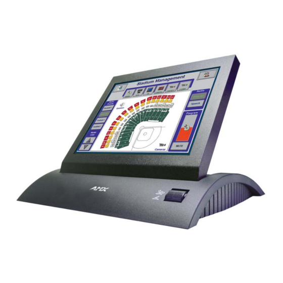
Product Information Product Information The AMX™ CA10, CV10 and CG10 touch panels contain a 10.4", 256-color active matrix liquid crystal display (LCD). The self-contained enclosures use a microprocessor to control a wide range of multimedia equipment. The TPDesign3 touch panel design program makes it possible to create custom pages with buttons, icons, sliders, bargraphs, time displays, logos, and drawings. -
Page 6: Cleaning The Touch Overlay
Product Information Specifications (Cont.) Power 12 VDC @ 1 A Memory Standard: 5 MB (4 MB flash) Weight: Decor • 6.0 lbs. (2.7 kg) Rack-mount • 6.0 lbs. (2.7 kg) TiltScreen • 4.6 lbs. (2.1 kg) VGA Input Resolutions: (The frame frequency [FF] calculations are based on monitor type and VGA settings.) 640 x 400 (DOS) FF: 70 Hz... -
Page 7: Installation
Installation Installation Mounting the Touch Panel The following paragraphs describe mounting the Decor and rack-mount touch panels. TiltScreen touch panels can be placed on any flat surface. Decor style panels with low-profile Backboxes 1. Cut out the surface using the dimensions shown in FIG. 1. FIG. - Page 8 Installation 5. Disconnect the AXlink connector from the Central Controller, RS-232 connector, and the optional graphic/video wiring from the external RS-232 device connected to the source equipment. 6. Thread the incoming AXlink, RS-232, and optional graphic/video wiring through the low- profile Backbox.
- Page 9 Installation FIG. 3 Decor style (AXD) and CB-TP3 cutout dimensions (solid surfaces) Carefully insert a flat-blade screwdriver into the release slot on the touch panel’s bezel and remove the engraved overlay. 3. Lay the touch panel facedown on a soft cloth and remove the screws from the low-profile Backbox;...
-
Page 10: Installing Touch Panels And A Cb-Tp3 Backbox (Plasterboard)
Installation 9. Fasten the CB-TP3 to the solid surface using the supplied mounting screws. The touch panel must be installed with the release slot at the bottom. 10. Connect the AXlink, RS-232, and optional graphic/video wiring to the touch panel. 11. - Page 11 Installation FIG. 5 Decor style (AXD) and CB-TP3 cutout dimensions for plasterboard 5. Remove the CB-TP3 and drill four #6-32 insert holes. Then, place a threaded insert (or screw anchor) into each hole. 6. Disconnect the AXlink connector from the Central Controller, RS-232 connector, and the optional graphic/video wiring from the source equipment.
-
Page 12: Installing Rack-Mount Panels (Axm-Ca10/Pb)
Installation 14. Remove the backing from the adhesive tape strips; press the engraved overlay onto the faceplate. Once attached to the faceplate, the security screws cannot be replaced without removing the overlay. 15. Reconnect the AXlink wiring to the Central Controller, RS-232 wiring to the mouse (if used), and optional graphic/video wiring to the source equipment. -
Page 13: Using The Psn Connector For Power
Installation The maximum wiring lengths for using AXlink power are based on a minimum of 13.5 VDC available at the Central Controller's power supply. Refer to the Specifications section on page 1 for more information on power requirements. Wiring Guidelines Maximum Wiring Length Wire Size Color Active... -
Page 14: Using Axlink For Data With A +12 Vdc Power Supply
Installation To the touch panel To the external Central Controller AXlinx/PWR connector Top view Top view FIG. 7 AXlink wiring diagram If you are using power from AXlink, disconnect the wiring from the Central Controller before wiring the touch panel. Using AXlink for data with a +12 VDC power supply To use the AXlink 4-pin connector for data communication with the Central Controller and power transfer from a power supply, the incoming PWR and GND cable from the power supply must be... -
Page 15: Using The (Db9) Rs-232 Connector For Mouse Control Or Data
Installation Never connect both power wires from the power supply and Central Controller to the PWR terminal on the touch panel AXlink connector. Only the power supply’s PWR wire should be connected to the touch panel AXlink connector. If both sources are used to provide power to the touch panel, an electrical hazard is created and the threat of both equipment damage and injury is likely. -
Page 16: Using The Vga In Hd-15 (Male) High-Density Connector
Installation Using the VGA IN HD-15 (male) high-density connector Connect the VGA source equipment’s HD-15 (female) connector to the VGA IN HD-15 (male) high-density connector on the rear panel of the touch panel. The table below lists the VGA IN HD-15 connector pinouts. - Page 17 Installation 10.4" Touch Panels...
- Page 18 Installation 10.4" Touch Panels...
-
Page 19: Designing Touch Panel Pages
Designing Touch Panel Pages Designing Touch Panel Pages There are two ways to approach creating touch panel pages: TPDesign3 - Refer to the TPDesign3 Touch Panel Program (Version 3. 16 or higher) Instruction Manual for more information. On-board editor This section describes the basics of using the on-board editor to create pages and buttons. For more information, refer to the G3 Firmware Design and Reference instruction manual. -
Page 20: Activating Edit Mode
Designing Touch Panel Pages General Button Categories (Cont.) Status buttons Status buttons always have a dark fill with light letters and have no functionality except to display information. Operation bars Operation bars appear in the place of the Editor bar, after selecting a button or page edit operation. - Page 21 Designing Touch Panel Pages FIG. 11 Setup page 4. Press to enable Edit mode. The button is highlighted in the Protected Setup EDITOR EDITOR page when enabled, as shown in FIG. 12. FIG. 12 Protected Setup page with the active EDITOR button 5.
-
Page 22: Setting The Device Base
Designing Touch Panel Pages Setting the Device Base Press the option, in the Protected Setup page (FIG. 12), to assign a base (starting) DEVICE BASE device address to the touch panel. 1. Enter the base address for the touch panel. The base address range is from 1 - 255. Standard device addresses begin at 128. -
Page 23: Resizing A Button
Designing Touch Panel Pages A Video signal can only be displayed within a Video WIndow Button. From the Edit bar, go to Button > Add. Touch the screen to size the button. Open Button > Properties and select Video Window from the Button Type section. Refer to the G3 Firmware instruction manual for more detailed information. -
Page 24: Setting The Variable Text Code
Designing Touch Panel Pages If DEVICE USED is set to 4 and Base Device Number is 128, the Controller recognizes bus devices 128 - 131. The panel will not allow you to enter a device number greater than the DEVICE USED without first displaying a decision box asking if you accept the new selection or not. -
Page 25: Setting The Button Colors For Channel-Off Conditions
Designing Touch Panel Pages Setting the button colors for channel-off conditions 1. Press any button to open the Button Properties page. 2. Press under in the Button Properties page. The color palette appears. BORDER CHANNEL OFF Select a color to set as the border. 3. -
Page 26: Creating A Bargraph And Joystick
Designing Touch Panel Pages 6. In the What To Send area, select one or more of the available options (All Bitmaps, All Icons, All Fonts). 7. Select the mode of communication with the touch panel (RS-232 and AXlink). Confirm that the correct panel is selected by verifying the ID values with the Base Address assigned to the touch panel in the Protected Setup page. - Page 27 Designing Touch Panel Pages 4. Press to open a keypad and set the level number assigned to the device. 5. Enter a number 1 – 8. Each device can have from 1 – 8 levels except joysticks, where the range is 1 –...
- Page 28 Designing Touch Panel Pages 10.4" Touch Panels...
-
Page 29: Programming
Programming Programming You can program the touch panel to perform a wide variety of operations using AXCESS Send_Commands and variable text commands. Use the commands described in this section to program the touch panel. Refer to the AXCESS Programming Language instruction manual for complete information. - Page 30 Programming Serial Commands (Cont.) ECHO ON Syntax: Turns On charac- "ECHO ON" ter echo. Example: ECHO ON The character echo is sent back to the computer. ECHO OFF Syntax: Turns Off charac- "ECHO OFF" ter echo. Example: ECHO OFF The character echo is not sent back to the computer. GET CAL Syntax: Gets the calibra-...
- Page 31 Programming Serial Commands (Cont.) SET CAL Syntax: Sets the calibra- “SET CAL <X Multiplier> <X Offset> <Y Multiplier> <Y tion variables. Offset>" Example: SET CAL 2F 3A 2B 62 Sets the calibration values on the touch panel. SETUP Syntax: Puts the touch "SETUP"...
-
Page 32: System Send_Commands
Programming System Send_Commands System Send_Commands are stored in the Controller and direct the touch panel to perform various operations. System Send_Commands Translates the ¦ and translates it as a carriage return to the next line. Sends data out Syntax: the serial port with "’$SP "<data>"’"... - Page 33 Programming System Send_Commands (Cont.) BAUD The baud rate can also be set in the Protected Setup page’s BAUD level indicator. Sets the program Syntax: port baud rate. "’BAUD <baud rate>’" Variable: baud rate = 38400, 19200, 9600, 4800, 2400, 1200, 600, and 300 Example: SEND_COMMAND TP,"’BAUD 38400’"...
- Page 34 Programming System Send_Commands (Cont.) DBEEP This command only works if the Double Beep value in the Protected Setup page is set to Gives a double beep output. Syntax: "’DBEEP’" Example: SEND_COMMAND TP,"’DBEEP’" Double beeps the panel. ILEV Syntax: Inverts the joystick "’ILEV <joystick axis to invert>’"...
- Page 35 Programming System Send_Commands (Cont.) PPOF Syntax: Closes a specific "’PPOF-<page name>’" popup page. Variable: page name = 1 - 50 ASCII characters Example: SEND_COMMAND TP,"’PPOF-Popup Page 1’" Closes Popup Page 1. PPON Syntax: Opens a specific "’PPON-<page name>’" popup page. Variable: page name = 1 - 50 ASCII characters Example:...
- Page 36 TPAGEON Syntax: Activates page "’TPAGEON’" tracking. Example: SEND_COMMAND TP,’TPAGEON’ DEFINE_DEVICE TP1 = 128 (*AMX Touch Panel*) TP2 = 129 (*AMX Touch Panel*) DEFINE_VARIABLE TP1_BUFFER[100] (*Buffer for TP1*) TP2_BUFFER[100] (*Buffer for TP2*) TRASH[50] (*For Parsing Above*) DEFINE_START CREATE_BUFFER TP1,TP1_BUFFER CREATE_BUFFER TP2,TP2_BUFFER...
-
Page 37: Video Send_Commands
Programming System Send_Commands (Cont.) TPAGEOFF Syntax: Deactivates page "’TPAGEOFF’" tracking. Example: SEND_COMMAND TP,"’TPAGEOFF’" Deactivates the page tracking option. WAKE Syntax: Deactivates "’WAKE’" screen-saver Example: mode and resets SEND_COMMAND TP,"’WAKE’" the sleep timer. Deactivates the touch panel screen-saver mode and resets the sleep timer. XMRT Syntax: Sets the new net-... - Page 38 Programming Video Send_Commands (Cont.) @VBW Syntax: Sets the video to "’@VBW <ASCII setting for Black/White input>’" black/white or Variables: color. Black/White input setting = 0: Color 1: Black and White Example: SEND_COMMAND TP,"’@VBW 1’" Sets the video output to black and white. @VCT Syntax: Sets the video...
-
Page 39: Vga Send_Commands
Programming Video Send_Commands (Cont.) @VSD Resets the following video attributes to their default settings: Resets video Brightness, Contrast, Saturation, Hue, Interlace default settings. Syntax: "’@VSD’" Example: SEND_COMMAND TP,"’@VSD’" Resets the video defaults. @VST Syntax: Sets the video "’@VST <ASCII setting for Saturation>’" saturation. - Page 40 Programming VGA Send_Commands (Cont.) VGGC Syntax: Sets the green "’VGGC-<ASCII setting for green intensity>’" VGA signal inten- Variable: sity (brightness). ASCII green intensity setting = 0 - 67 Example: SEND_COMMAND TP,"’VGGC-0’" Sets the green VGA signal intensity to 0 (minimum). VGHP Syntax: Moves the VGA...
-
Page 41: Programming Numbers
Programming VGA Send_Commands (Cont.) VGVP Syntax: Moves the VGA "’VGVP-<ASCII setting for vertical position>’" display vertically Variable: up or down. ASCII vertical position setting = 0 - 15 Examples: SEND_COMMAND TP,"’VGVP-10’" Centers the VGA display vertically. Programming Numbers The following information provides the programming numbers for colors, fonts, and borders Colors can be used to set the colors on buttons, sliders, gauges, and pages. -
Page 42: Shorthand Send_Commands
Programming Border styles can be used to program borders on buttons, sliders, and gauges. Border Styles and Programming Numbers Border styles Border styles No border Double shadow No border special 3-dimensional rectangle 1 Single line 3-dimensional rectangle 2 Double line 3-dimensional round 1 Triple line 3-dimensional round 2... - Page 43 Programming Shorthand Send_Commands (Cont.) @CFF This only works if the specified background color is not the same as the current color. Sets the OFF Syntax: feedback fill color "’@CFF’,<variable text address>,<color_number>" to the specified Variables: color. variable text address = 1 - 255 color number = See the Colors and Programming Numbers table on page 37.
- Page 44 Programming Shorthand Send_Commands (Cont.) @CTN This only works if the specified background color is not the same as the current color. Sets the ON feed- Syntax: back text color to "’@CTN’,<variable text address>,<color_number>" the specified Variables: color. variable text address = 1 – 255 color number = See the Colors and Programming Numbers table on page 37.
- Page 45 Programming Shorthand Send_Commands (Cont.) @PPF If a page name is empty, the current page is used. If a pop-up page is part of a group, the whole group is deactivated. Deactivates a popup page on a Syntax: touch panel page. "’@PPF-<popup page name>;<page name>’"...
- Page 46 Programming Shorthand Send_Commands (Cont.) @PWD Syntax: Sets the password "’@PWD-<page flip password>’" for the Page Flip Variable: on the touch page flip password = 0 - 9999 panel. Example: SEND_COMMAND TP,"’@PWD-1988’" Sets the page flip password to 1988. @RDW Syntax: Redraws the cur- "’@RDW’"...
-
Page 47: Color Send_Commands
Programming Color Send_Commands Use the color Send_Commands to set the colors for text, buttons, and pages. Use the same command for setting gray scale values only change the color number value to reflect the gray scale (72-86) value. Color Send_Commands CALL You must use the variable text assignments to change button colors (see the Colors and Programming Numbers table on page 37). - Page 48 Programming Color Send_Commands (Cont.) CFOFF Syntax: Sets the OFF "’CFOFF<variable text address>-<color_number>’" feedback fill color Variables: to the specified variable text address = 1 - 255 color. color number = See the Colors and Programming Numbers table on page 37. Example: SEND_COMMAND TP,"’CFOFF1-72’"...
-
Page 49: Variable Text Send_Commands
Programming Variable Text Send_Commands Use variable text Send_Commands to set the borders, fonts, and text. Variable Text Send_Commands Syntax: "’!B’,<variable text address>,<ON/OFF>" Sets a specific button to On or Variables: Off. variable text address = 1 - 255 ON = 0 OFF = 1 Example: SEND_COMMAND TP,"’!B’,128,1"... - Page 50 Programming Variable Text Send_Commands (Cont.) FONT Syntax: "’FONT<variable text address>-<font size>’" Changes the font size (or style) of Variables: the text in a spe- variable text address = 1 - 255 cific button. font size = See the Font Styles and Programming Numbers table on page 37. Example: SEND_COMMAND TP,"’FONT1-6’"...
-
Page 51: Shorthand Variable Text Commands
Programming Shorthand Variable Text Commands The table below lists the shorthand variable text commands you can use with the touch panel. The shorthand command data is one-byte, non-ASCII format except for pages, passwords, text, and bitmap names. Shorthand Variable Text Commands @BMF This command allows you to program up to 12 attributes on one command line. - Page 52 Programming Shorthand Variable Text Commands (Cont.) @BOR Syntax: Sets the border "’@BOR’,<variable text address>,<border style>" style on a button. Variables: variable text address = 1 - 255 border style = See the Border Styles and Programming Numbers table on page 38. Example: SEND_COMMAND TP,"’@BOR’,65,11"...
- Page 53 Programming Shorthand Variable Text Commands (Cont.) @JUS Syntax: Sets the text "’@JUS’,<variable text address>,<text alignment>" alignment on a Variables: button. variable text address = 1 - 255 text alignment = 1 - 9 as shown in the following alignment chart Example: SEND_COMMAND TP,"’@JUS’,9,5"...
-
Page 54: Button String Commands
Programming Button String Commands The table below lists string commands you can assign to buttons by using the touch panel editor. Select the PROPERTIES option in the Edit bar, press the target button, and enter the string command with the Touch Panel keyboard. The string command is sent to the control system when you press the button. - Page 55 Programming Button String Commands (Cont.) Syntax: Sends data out "$SP"<data>"" through the serial Variables: port of the source data = Serial string command panel to a destina- tion panel. Examples: $SP "CALIBRATE" Sends the Calibrate command to another panel through the Serial Port. $SP "$SC 1,"’@TXT’,1,’TEST’""...
- Page 56 Programming 10.4" Touch Panels...
-
Page 57: Upgrading The Firmware
The NetLinx Studio application can perform firmware upgrades for both Axcess and NetLinx devices using the options in the NetLinx Studio Firmware sub-menu. BEFORE beginning, download the correct TSK files from the AMX.com website. Refer to the NXC-ME260 Instruction manual for detailed setup information. - Page 58 FIG. 16 Sample NetLinx Project Navigator window 9. Right-click on the touch panel and select Properties to confirm the on-board firmware. Download the latest firmware file from AMX.COM > Tech Center > Downloadable FIles > Firmware Files > AXT-CA10, AXT-CV10, AXT-CG10. Then Download the TSK file to your computer.
-
Page 59: Upgrading The Firmware Through An Ip Address
Upgrading the Firmware Selected Firmware file Device number listing of detected Axcess devices Device, Port and system number of panel. Query Online Devices allows the user to refresh the list of detected Axcess devices FIG. 17 Select New 10.4 Firmware File for download page 17. - Page 60 FIG. 19 Sample NetLinx Project Navigator window 10. Right-click on the touch panel and select Properties to confirm the on-board firmware. Download the latest firmware file from AMX.COM > Tech Center > Downloadable FIles > Firmware Files > AXT-CA10, AXT-CV10, AXT-CG10. Then Download the TSK file to your computer.
-
Page 61: Upgrading The Firmware Using Softrom
RAM to flash memory, the unit will not operate at all when power returns. If you have not already installed the SoftROM program, do so by logging into the AMX.com site and going to Dealers > Tech Center > Downloadable Files > Firmware Files. Scroll-down the list of products to find the AXT-CA10, AXT-CV10, AXT-CG10 firmware TSK files. -
Page 62: Configuration
Upgrading the Firmware Configuration To configure the communication setting for the SoftROM program: 1. Press F1 to open the Configuration screen. 2. Using the up/down arrow keys, select the communications port you are using to interface with the controller and press ENTER. 3. -
Page 63: Changing The Lcd Viewing Angle
Changing the LCD Viewing Angle Changing the LCD Viewing Angle You can reset the viewing angle on the Decor-style wall mount and Rack-mount touch panels to accommodate the various installation locations and viewing angles. The two most frequent locations are on a wall or podium. In the first location (wall), a user is looking at the screen from a 12 o’clock position (looking down on it). - Page 64 Changing the LCD Viewing Angle Jumper 6 3 2 1 FIG. 20 Open circuit card and JP6 jumper location Bezel mounting screws Rotate bezel 180 degrees Bezel/faceplate Release slot FIG. 21 Bezel mounting screws and release slot locations 17. Place the engraved overlay back onto the touch panels’ bezel/faceplate. 10.4"...
-
Page 65: Replacing The Batteries
Replacing the Batteries Replacing the Batteries There are two lithium batteries on the touch panel card, with a life of approximately 2.5 years. They protect stored commands and pages against a power outage. The batteries are not used when DC power is supplied to the touch panel. - Page 66 ATLANTA • BOSTON • CHICAGO • CLEVELAND • DALLAS • DENVER • INDIANAPOLIS • LOS ANGELES • MINNEAPOLIS • PHILADELPHIA • PHOENIX • PORTLAND • SPOKANE • TAMPA 3000 RESEARCH DRIVE, RICHARDSON, TX 75082 USA • 800.222.0193 • 469.624.8000 • 469-624-7153 fax • 800.932.6993 technical support • www.amx.com...