Table of Contents
Advertisement
Advertisement
Table of Contents

Related Manuals for AMX MXTD-1000


Summary of Contents for AMX MXTD-1000
- Page 1 I n s t r u c t i o n M a n u a l Modero X-Series Touch Panels MXT/D-1000 - 10.1" Modero X Series Touch Panels MXT/D-700 - 7" Modero X Series Touch Panels MXD-430 - 4.3" Modero X Series Touch Panels L a s t R e v is e d : 8 / 2 0 / 2 0 1 4 M o d e r o X S e r i e s T o u c h P a n e l s...
- Page 2 AMX is not responsible for products returned without a valid RMA number. AMX is not liable for any damages caused by its products or for the failure of its products to perform. This includes any lost profits, lost savings, incidental damages, or consequential damages.
-
Page 3: Table Of Contents
Table of Contents Table of Contents Modero X Series Touch Panels (10.1", 7"& 4.3") ..........1 Overview ........................1 Sleep Button ......................2 Settings Page......................2 Accessing the Settings Page ................... 2 Using the Settings Pages....................2 Bluetooth Support ....................2 NFC Support...................... - Page 4 Removing an MXD-430 from Its Backbox..............51 Upgrading Firmware ..................53 Overview ........................ 53 Downloading Firmware Updates From www.amx.com ........... 53 Upgrading Firmware via USB Flash Drive ............... 53 Load the Firmware on a USB Flash Drive ..............53 Transfer the Firmware File From the Flash Drive to the Touch Panel......54 Upgrading from Previous Firmware ................
-
Page 5: Modero X Series Touch Panels (10.1", 7"& 4.3")
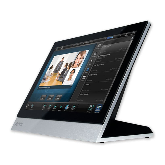
Modero X Series Touch Panels (10.1", 7"& 4.3") Modero X Series Touch Panels (10.1", 7"& 4.3") Overview This new generation of G4 touch panels is built for usability offering edge-to-edge capacitive touch glass with multi- touch capabilities. It features advanced technology empowering users to operate AV equipment seamlessly, while providing the ultimate in audio and video quality. -
Page 6: Sleep Button
If the device has gone into its Sleep Mode, a touch of the touchscreen or of the Sleep button will reactivate it. Settings Page Unlike previous AMX touch panels, Modero X Series touch panels no longer have separate Setup and Protected Setup pages. All touch panel settings and functionality are now controlled through one Settings page. The Connection &... -
Page 7: Nfc Support
Modero X Series Touch Panels (10.1", 7"& 4.3") NFC Support X Series touch panels support Near Field Communications™ (NFC) Technology. NFC technology facilitates making transactions, exchanging digital content, and connecting electronic devices with a touch. NFC transmissions are short- range (from a touch to a few centimeters), working with existing contact-less card technologies and containing built-in capabilities to support secure applications. -
Page 8: Starting Picture View
Modero X Series Touch Panels (10.1", 7"& 4.3") Starting Picture View Connect a USB drive to the device. Picture View will automatically recognize all available images on the drive and start displaying them on the touchscreen. When the images begin to display, touch any place on the touchscreen to open the configuration popup menu (FIG. -
Page 9: Picture View Send Command (^Pic)
FIG. 6 shows an AMX device installed in a wall with a filled volume (such as with insulation or concrete), as well as with a closed volume (such as between studs in an otherwise finished wall). The diagram shows how heat generated by the device or other devices may have no way to escape, and may build up to levels that may affect device operation. -
Page 10: Installation Recommendations
Modero X Series Touch Panels (10.1", 7"& 4.3") FIG. 7 Heat convection in rack-mounted devices Installation Recommendations During any installation, a lack of ventilation may produce conditions that may adversely affect the device’s operation. In these circumstances, special care must be made to make sure that temperatures within enclosed areas do not exceed the device’s maximum rated temperature. -
Page 11: Mxt/D-1000 - 10.1" X Series Panels
• Shutdown: 1 W • Start-Up Inrush Current: Not applicable due to PoE standard EXTERNAL POWER Optimal performance requires use of one of the following AMX PoE power supplies (not SUPPLY REQUIRED included): • PS-POE-AF-TC, PoE Injector, 802.3AF Compliant (FG423-83) •... - Page 12 • Audio Output: USB Audio out USB port (head/hand set support) • File Formats: WAV, MP3 (as part of touch panel file only - no USB storage) • Intercom: Full Duplex VoIP, SIP v2.0 (supported with AMX-CSG) MXD/T-1000, MXD/T-700 and MXD-430 Modero X Series® Touch Panels...
-
Page 13: Touch Panel Aspect Ratio
AMX G4: G4 enhanced feature set supporting multi-touch and gestures, scrolling, transitions - See TPD4 Operations Guide for more information EMBEDDED APPLICATIONS • Remote Management: VNC Server, G4 Web Control, AMX Resource Management Suite • Video Conferencing: Panel-to-panel and video chat •... -
Page 14: Mxt-1000 Installation
MXT/D-1000 - 10.1" X Series Panels MXT-1000 Installation Detailed specifications drawings for the MXT-1000 are available to download from www.amx.com. Top View Front View Side View Rear View FIG. 9 MXT-1000 Connector Locations USB peripherals (mouse, keyboard, etc.) may be connected to either of the two USB ports on the rear of the device (FIG. -
Page 15: Power Via Poe
MXT/D-1000 - 10.1" X Series Panels Power via PoE Power for the MXT-1000 is supplied via PoE (Power Over Ethernet ), utilizing an AMX-certified, capacitive touch- compliant PoE injector such as the PS-POE-AT High Power PoE Injector (FG423-81) or other approved AMX PoE power source. -
Page 16: Mxd-1000 (Wall-Mount - Landscape/Portrait)
• Shutdown: 1 W • Start-Up Inrush Current: Not applicable due to PoE standard EXTERNAL POWER Optimal performance requires use of one of the following AMX PoE power supplies (not SUPPLY REQUIRED included): • PS-POE-AF-TC, PoE Injector, 802.3AF Compliant (FG423-83) •... - Page 17 MXT/D-1000 - 10.1" X Series Panels MXD-1000 Specifications (Cont.) TOUCH SCREEN DISPLAY • Display Type: TFT Active Matrix Color LCD with In-plane Switching Technology (IPS) • Display Size (WH) Landscape: 9.9" x 6.7" (252 mm x 170 mm), 12.0" (304 mm) diagonal Portrait: 6.7"...
- Page 18 AMX G4: G4 enhanced feature set supporting multi-touch and gestures, scrolling, transitions - See TPD4 Operations Guide for more information EMBEDDED APPLICATIONS • Remote Management: VNC Server, G4 Web Control, AMX Resource Management Suite • Video Conferencing: Panel-to-panel and video chat •...
-
Page 19: Touch Panel Aspect Ratio
MXT/D-1000 - 10.1" X Series Panels MXD-1000 Specifications (Cont.) ENVIRONMENTAL • Temperature (Operating): 32° F to 104° F (0° C to 40° C) • Temperature (Storage): 4° F to 140° F (-20° C to 60° C) • Humidity (Operating): 20% to 85% RH •... -
Page 20: Mxd-1000 Installation
MXD-1000 Installation Detailed specifications drawings for the MXD-1000 are available to download from www.amx.com. Refer to A Note About Wall and Rack Installation on page 5 for important notes on thermal concerns with Rack and Wall installations. The MXD-1000 may be installed directly into a solid surface environment, using either solid surface screws or the included locking tabs for different mounting options. - Page 21 MXT/D-1000 - 10.1" X Series Panels Backbox knockouts (X4) Locking tabs (X4) Backbox FIG. 14 MXD-1000 (Landscape) Note: Dimensions in parenthesis are in millimeters FIG. 15 MXD-1000 In order to ensure a stable installation of the MXD-1000, the thickness of the wall material must be a minimum of .50 inches (1.27cm) and a maximum of .875 inches (2.22cm).
-
Page 22: Installing The Backbox
MXT/D-1000 - 10.1" X Series Panels Installing the Backbox Note: Dimensions in parenthesis are in millimeters FIG. 16 MXD-1000 Installation Dimensions (front view) Note: Dimensions in parenthesis are in millimeters FIG. 17 MXD-1000 Installation Dimensions (side view) For best results, use the included Installation Template (68-5968-03) to ensure proper placement. Using the Installation Template to select the final placement of the Backbox is highly recommended. - Page 23 MXT/D-1000 - 10.1" X Series Panels 9 7/8" (25.08cm) 8 3/4" (22.23cm) 6 3/4" (17.15cm) 5 1/2" (13.97 m) FIG. 18 10" Installation Template Prepare the area by removing any screws or nails from the drywall before beginning the cutout process. After ensuring proper placement, cut out the mounting surface for the Backbox, using the included Installation Template as a guide.
- Page 24 MXT/D-1000 - 10.1" X Series Panels 4X Installation Clamp for Wall Thickness .31 [12.0] to .98 [.25.0] 4X Knock-Outs Remove for Cable Routing as Needed #4 Screws FIG. 19 MXD-1000 Backbox Installation (Landscape) MXD/T-1000, MXD/T-700 and MXD-430 Modero X Series® Touch Panels...
- Page 25 MXT/D-1000 - 10.1" X Series Panels 4X Installation Clamp for Wall Thickness .31 [12.0] to .98 [.25.0] 4X Knock-Outs Remove for Cable Routing as Needed #4 Screws FIG. 20 MXD-1000 Backbox Installation (Portrait) Remove the Backbox knockouts (FIG. 19) and thread the incoming wiring through the knockout holes. To facilitate installation, thread the Ethernet cable through a bottom knockout (Landscape) or a right-side knockout (Portrait), and the Micro-USB or USB cables through a top knockout (Landscape) or left knockout (Portrait) Thread the incoming Ethernet, USB, and Micro-USB wiring (if USB or Micro-USB access is desired) from the...
- Page 26 MXT/D-1000 - 10.1" X Series Panels The Backbox is clear to allow visual confirmation that the tabs have been extended and are gripping the wall, as well as in assisting with removal if necessary. For additional strength, #4 mounting screws (not included) may be secured through circular holes located at the left and right sides of the MXD-1000 (FIG.
- Page 27 MXT/D-1000 - 10.1" X Series Panels MXD-1000 (Landscape) Latch Hook Latch Hook Mounting Surface Backbox Snaps FIG. 22 Installing the MXD-1000 (Landscape) If a gap is observed between the panel and the Backbox, or feel any binding while locking down the panel, stop immediately and verify that no cables or other items are in the way.
-
Page 28: Removing The Mxd-1000
MXT/D-1000 - 10.1" X Series Panels Removing the MXD-1000 The MXD-1000 is held in place via latch hooks and clips in the Backbox. In certain circumstances, such as firmware updates or other maintenance that requires accessing the device’s USB or Micro-USB ports, the device may need to be removed from the Backbox. - Page 29 Be careful not to pull on the cables or connectors. To reattach the panel to its Backbox, repeat the installation procedure. For further information, refer to the video available at www.amx.com (go to Newsroom > Videos > Touch Panels). MXD/T-1000, MXD/T-700 and MXD-430 Modero X Series® Touch Panels...
- Page 30 MXT/D-1000 - 10.1" X Series Panels MXD/T-1000, MXD/T-700 and MXD-430 Modero X Series® Touch Panels...
-
Page 31: Mxt/D-700 - 7" X Series Panels
• Shutdown: 1 W • Start-Up Inrush Current: Not applicable due to PoE standard EXTERNAL POWER Optimal performance requires use of one of the following AMX PoE power supplies (not SUPPLY REQUIRED included): • PS-POE-AF-TC, PoE Injector, 802.3AF Compliant (FG423-83) •... - Page 32 • Intercom: Full Duplex VoIP, SIP v2.0 (supported with AMX-CSG) GRAPHICS ENGINE AMX G4: G4 enhanced feature set supporting multi-touch and gestures, scrolling, transitions - See TPD4 Operations Guide for more information MXD/T-1000, MXD/T-700 and MXD-430 Modero X Series® Touch Panels...
-
Page 33: Touch Panel Aspect Ratio
MXT/D-700 - 7" X Series Panels MXT-700 Specifications (Cont.) EMBEDDED APPLICATIONS • Remote Management: VNC Server, G4 Web Control, AMX Resource Management Suite • Video Conferencing: Panel-to-panel and video chat (the MXT-700 receives video and returns audio) • Audio Conferencing: Audio (Full Duplex Intercom) FRONT PANEL •... -
Page 34: Mxt-700 Installation
MXT/D-700 - 7" X Series Panels MXT-700 Installation Detailed specifications drawings for the MXT-700 are available to download from www.amx.com. Top View Front View Side View Rear View FIG. 26 MXT-700 Connector Locations USB peripherals (mouse, keyboard, etc.) may be connected to either of the two USB ports on the rear of the device (FIG. -
Page 35: Power Via Poe
MXT/D-700 - 7" X Series Panels Power via PoE Power for the MXT-700 is supplied via PoE (Power Over Ethernet ), utilizing an AMX-certified, capacitive touch- compliant PoE injector such as the PS-POE-AT High Power PoE Injector (FG423-81) or other approved AMX PoE power source. -
Page 36: Mxd-700 (Wall-Mount - Landscape/Portrait)
• Shutdown: 1 W • Start-Up Inrush Current: Not applicable due to PoE standard EXTERNAL POWER Optimal performance requires use of one of the following AMX PoE power supplies (not SUPPLY REQUIRED included): • PS-POE-AF-TC, PoE Injector, 802.3AF Compliant (FG423-83) •... - Page 37 MXT/D-700 - 7" X Series Panels MXD-700 Specifications (Cont.) TOUCH SCREEN DISPLAY • Display Type: TFT Active Matrix Color LCD with Fringe Field Switching (FFS) - Wide Viewing Angle Technology • Display Size (WH) Landscape: 7.3" x 4.8" (186 mm x 122 mm), 8.8" (222 mm) diagonal Portrait: 4.8"...
- Page 38 AMX G4: G4 enhanced feature set supporting multi-touch and gestures, scrolling, transitions - See TPD4 Operations Guide for more information EMBEDDED APPLICATIONS • Remote Management: VNC Server, G4 Web Control, AMX Resource Management Suite • Video Conferencing: Panel-to-panel and video chat (the MXD-700 receives video and returns audio) •...
-
Page 39: Touch Panel Aspect Ratio
(not included). Power Via PoE Power for the MXD-700 is supplied via PoE (Power Over Ethernet), utilizing an AMX-certified, capacitive touch- compliant PoE injector or other approved AMX PoE power source. The incoming Ethernet cable connects to the RJ45 port on the MXD-700 (see FIG. 30). - Page 40 MXT/D-700 - 7" X Series Panels Backbox knockouts (X4) Locking tabs (X2) Backbox FIG. 31 MXD-700 (Landscape) Note: Dimensions in parenthesis are in millimeters FIG. 32 MXD-700 MXD/T-1000, MXD/T-700 and MXD-430 Modero X Series® Touch Panels...
-
Page 41: Installing The Backbox
MXT/D-700 - 7" X Series Panels In order to ensure a stable installation of the MXD-700, the thickness of the wall material must be a minimum of .50 inches (1.27cm) and a maximum of .875 inches (2.22cm). The mounting surface should also be smooth and flat. Installing the Backbox For best results, use the included Installation Template (68-5968-04) to ensure proper placement. - Page 42 MXT/D-700 - 7" X Series Panels Using the Installation Template to select the final placement of the Backbox is highly recommended. The outside edges of the template are the same dimensions as the touch panel, which allows you to troubleshoot possible conflicts with wall edges, doors, and other potential obstacles.
- Page 43 MXT/D-700 - 7" X Series Panels 4X Knock-Outs Remove for Cable Routing as Needed 2X Installation Clamp for Wall Thickness .37 [12.03] to .98 [.25.0] #4 Screws FIG. 36 MXD-700 Backbox Installation (Portrait) Leave enough slack in the wiring to accommodate any re-positioning of the panel. Remove the Backbox knockouts and thread the incoming wiring through the knockout holes.To facilitate installation, thread the Ethernet cable through a bottom knockout (Landscape) or a right-side knockout (Portrait), and the USB cable through a top knockout (Landscape) or left knockout (Portrait)
- Page 44 MXT/D-700 - 7" X Series Panels Insert each connector into its corresponding location along the back of the device. To reach the RJ45 connector, gently pull it from beneath the electronics cover. Attach the Ethernet cable and gently push the connection back under the cover. To facilitate connection of the RJ45 connector to the Ethernet cable, press the RJ45’s cable into the RJ45 cable clip to hold it in a stable position.
-
Page 45: Removing The Mxd-700
MXT/D-700 - 7" X Series Panels Removing the MXD-700 The MXD-700 is held in place to the Backbox via latch hooks and clips on the Backbox, securing it to the mounting surface. In certain circumstances, such as firmware updates or other maintenance that requires accessing the device’s USB port, the device may need to be removed from the Backbox. - Page 46 Backbox. Be careful not to pull on the cables or connectors. To reattach the panel to its Backbox, repeat the installation procedure. For further information, refer to the video available at www.amx.com (go to Newsroom > Videos > Touch Panels).
-
Page 47: Mxd-430 4.3" X Series Wall/Flush Mount Touch Panel
• Shutdown: 1.9 W • Start-Up Inrush Current: Not applicable due to PoE standard EXTERNAL POWER Optimal performance requires use of one of the following AMX PoE power supplies (not SUPPLY REQUIRED included): • PS-POE-AF-TC, PoE Injector, 802.3AF Compliant (FG423-83) •... - Page 48 • Audio Output: USB Audio out USB port (head/hand set support) • File Formats: WAV, MP3 (as part of touch panel file only - no USB storage) • Intercom: Full Duplex VoIP, SIP v2.0 (supported with AMX-CSG) MXD/T-1000, MXD/T-700 and MXD-430 Modero X Series® Touch Panels...
- Page 49 AMX G4: G4 enhanced feature set supporting multi-touch and gestures, scrolling, transitions - See TPD4 Operations Guide for more information EMBEDDED APPLICATIONS • Remote Management: VNC Server, G4 Web Control, AMX Resource Management Suite • Video Conferencing: Panel-to-panel and video chat (the MXD-430 receives video and returns audio) •...
-
Page 50: Mxd-430 Installation
Power for the MXD-430 is supplied via Power Over Ethernet (PoE), utilizing an AMX-certified, capacitive touch- compliant PoE injector or other approved AMX PoE power source. The incoming PoE Ethernet cable should be connected to the RJ45 port on the MXD-430 (FIG. 40). -
Page 51: Installing The Mxd-430 Into A Wall
MXD-430 4.3” X Series Wall/Flush Mount Touch Panel Installing the MXD-430 into a Wall The MXD-430 comes with a clear plastic backbox (designed to attach the panel to most standard wall materials. This backbox has two locking tabs (one on each side) to help lock the backbox to the wall. These locking tabs are only extended AFTER the backbox is inserted into the wall. - Page 52 MXD-430 4.3” X Series Wall/Flush Mount Touch Panel Using the included template to select the final placement of the Backbox is highly recommended. The outside edges of the template are the same dimensions as the touch panel, which allows you to troubleshoot possible conflicts with wall edges, doors, and other potential obstacles.
- Page 53 MXD-430 4.3” X Series Wall/Flush Mount Touch Panel Apply enough pressure to the screw head to keep the box flush with the wall: this ensures that the locking tabs will tighten up against the inside of the wall. The Backbox is clear to allow visual confirmation that the tabs have been extended and are gripping the wall, as well as in assisting with removal if necessary.
- Page 54 MXD-430 4.3” X Series Wall/Flush Mount Touch Panel Snap Backbox Mounting Surface Latch Hooks FIG. 46 Installing the MXD-430 If you see a gap between the panel and the Backbox or feel any binding while locking down the panel, stop immediately and verify that no cables or other items are in the way.
-
Page 55: Uninstalling The Mxd-430
MXD-430 4.3” X Series Wall/Flush Mount Touch Panel Uninstalling the MXD-430 The MXD-430 is held in place to the Backbox via latch hooks and a clip on the Backbox (FIG. 46), securing it to the mounting surface. In certain circumstances, such as firmware updates or other maintenance that requires accessing the device’s USB port, the device may need to be removed from the Backbox. - Page 56 MXD-430 4.3” X Series Wall/Flush Mount Touch Panel With a stout, strong point (a push pin or straightened paper-clip, for example), carefully press straight into the access holes in the center of the molding (FIG. 48) until the snap is disconnected. Grasp the top of the panel and pull gently outward until the side of the panel is free of the snap.
-
Page 57: Upgrading Firmware
FIG. 49: FIG. 49 www.amx.xom - X Series Touch Panel Product Page - Firmware File link Note that for X Series touch panels, the firmware .KIT file is bundled in a ZIP file that typically also includes a Readme.TXT file (which provides details on this version of firmware), and a Programming Instructions.TXT file... -
Page 58: Transfer The Firmware File From The Flash Drive To The Touch Panel
Upgrading Firmware Directory Names for Firmware Files - by Touch Panel Type Directory Name Panel Type(s) "MXT-1000" MXT-1000 (FG5968-03) MXT-1000-NC (FG5968-24) "MXD-1000" MXD-1000-P (FG5968-07) MXD-1000-P-NC (FG5968-25) MXD-1000-L (FG5968-13) MXD-1000-L-NC (FG5968-26) "MXT-700" MXT-700 (FG5968-04) MXT-700-NC (FG5968-27) "MXD-700" MXD-700-P (FG5968-08) MXD-700-P-NC (FG5968-28) MXD-700-L (FG5968-14) MXD-700-L-NC (FG5968-29) "MXD-430"... -
Page 59: Upgrading From Previous Firmware
X Series panels use Kit files for firmware upgrades. A Kit file (*.kit) is a package of several files, all of which are required to upgrade the firmware, and are available online via www.amx.com (refer to the device page for firmware updates). -
Page 60: Transferring The Kit File Via Netlinx Studio
Upgrading Firmware Transferring the KIT File via NetLinx Studio In Netlinx Studio, right-click in the Online Tree tab of the Workspace window and select Refresh System Online Tree to refresh the device listing. The touch panel should be indicated in the device list. Right-click on the target panel and select Firmware Transfer to open the Send to NetLinx Device dialog. -
Page 61: Appendix: Troubleshooting
Appendix: Troubleshooting Appendix: Troubleshooting Overview This section describes the solutions to possible hardware/firmware issues that could arise during the common operation of a Modero X Series touch panel. Panel Doesn’t Respond to Touches Symptom: The device either does not respond to touches on the touch screen or does not register the touch as being in the correct area of the screen. - Page 62 It’s Your World - Take Control™ 3000 RESEARCH DRIVE, RICHARDSON, TX 75082 USA • 800.222.0193 • 469.624.8000 • 469-624-7153 fax • 800.932.6993 technical support • www.amx.com...