AMX MXT-701 Operation/Reference Manual
7" modero x series g5 touch panel
Hide thumbs
Also See for MXT-701:
- Quick start manual (2 pages) ,
- Installation & hardware reference manual (54 pages)

Related Manuals for AMX MXT-701


Summary of Contents for AMX MXT-701
- Page 1 Operation/Reference Guide MXT/D-701 7" Modero X Series® G5 Tabletop Touch Panel 7" Modero X Series® G5 Wall/Flush Mount Touch Panel Touch Panels I n i t i a l R e l e a s e : 3 / 1 8 / 2 0 1 4...
- Page 2 AMX is not responsible for products returned without a valid RMA number. AMX is not liable for any damages caused by its products or for the failure of its products to perform. This includes any lost profits, lost savings, incidental damages, or consequential damages.
-
Page 3: Table Of Contents
Connector Locations......................4 A Note On The Touch Panel Aspect Ratio............... 4 Memory ........................... 4 Basic Operation ....................... 4 Powering on the MXT-701 ....................5 Microphone ........................5 Audio/Video Capabilities....................5 MXD-701........................5 A Note On The Touch Panel Aspect Ratio............... 8 Memory ........................... - Page 4 Table of Contents Upgrading Firmware ..................23 Overview ........................ 23 Upgrading Firmware via USB Flash Drive ............... 23 Load the Firmware on a USB Flash Drive ..............23 Transfer the Firmware File From the Flash Drive to the Touch Panel......23 Removing All Data From The Touch Panel ..............
-
Page 5: Modero X Series G5 Touch Panels
Modero X Series® G5 Touch Panels ® Modero X Series G5 Touch Panels Overview The most elegant interface designed specifically for dedicated room control has been significantly enhanced to include a new G5 Graphic Engine to provide even faster and smoother animations and transitions, and we quadrupled the processing power with a new Quad Core Processor. -
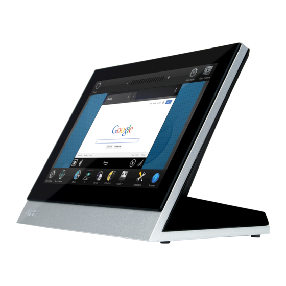
Page 6: Mxt-701
FIG. 1 MXT-701 touch panel The MXT-701 features a 7.3" x 4.8" (186 mm x 122 mm), 8.8" (222 mm) diagonal display, with a viewable area of 6.05" x 3.54" (154 mm x 90 mm), 7.0" (178 mm) diagonal. The device communicates via Ethernet (10/100 port, RJ-45 connector, supported IP and IP-based protocols: UDP, TCP, ICMP, ICSP, IGMP, DHCP, SSH, DNS, RFB for VNC, and HTTP) and USB (2 USB host 2.0, Type A ports). - Page 7 Modero X Series® G5 Touch Panels MXT-701 Specifications Power Requirements: PoE (Power over Ethernet), 802.3af, class 3 Power Consumption: • Full-On: 11.5 W maximum • Standby: 5.8 W • Shutdown: 1 W Front Panel Components: NFC Transceiver: Antenna and transceiver for Near Field Communications device detection and interaction.
-
Page 8: Connector Locations
16:9 if needed. This may lead to some letter boxing around the video in some cases. Memory The MXT-701 comes with 2GB of SDRAM and 16GB of Flash memory, neither of which can be upgraded. A maximum of 12GB is available to the user for projects. -
Page 9: Powering On The Mxt-701
Modero X Series® G5 Touch Panels The MXT-701 is operated using its integral touchscreen, as well as the Sleep/Settings button on the top of the device (FIG. 1). If the device has gone into its Sleep Mode, a touch of the touchscreen or of the Sleep/Settings button will reactivate it. - Page 10 Modero X Series® G5 Touch Panels Sleep/Settings Button NFC Sensor FIG. 5 MXD-701 (Portrait Wall Mount) MXD-701 Specifications Power Requirements: PoE (Power over Ethernet), 802.3af, class 3 Power Consumption: • Full-On: 11.5 W maximum • Standby: 5.8 W • Shutdown: 1 W Front Panel Components: NFC Transceiver: Antenna and transceiver for Near Field Communications device detection and interaction.
- Page 11 • MXA-CLK Modero X Series Cleaning Kit (FG5968-16) • MXD-701 Installation Template (68-5968-04) • MXD-701 Back Box (68-5968-04) Other AMX Equipment: • PS-POE-AF-TC, POE Injector, 802.3af Compliant (FG423-83) • CB-MXP7, Rough-In Box and Cover Plate for Modero X Series Touch Panel, 7"...
-
Page 12: A Note On The Touch Panel Aspect Ratio
Modero X Series® G5 Touch Panels - Feature will be supported in a future firmware update Port RJ45 Cable Clip RJ45 Port FIG. 6 Rear of the MXD-701 (Landscape) A Note On The Touch Panel Aspect Ratio While the touch panel's screen’s physical dimensions fall between 16:9 and 16:10, any incoming video stream can be scaled to 16:9 if needed. -
Page 13: Mxd/T-701 Features
Configuration The MXT-701 and MXD-701 are equipped with a Settings app that allows you to set and configure various features on the panels. For more information on connecting and configuring the touch panels to a network, please refer to the Modero X Series G5 Programming Guide, available at www.amx.com. - Page 14 Modero X Series® G5 Touch Panels MXD/T-701 7" Modero X Series® G5 Touch Panels...
-
Page 15: Installation
Power for the MXT-701 is supplied via Power Over Ethernet (PoE), utilizing an AMX-certified, capacitive touch- compliant PoE injector or other approved AMX PoE power source. The incoming Ethernet cable should be connected to the RJ45 port on the cable attached to the device (FIG. 8). - Page 16 FIG. 9 Bottom of the MXT-701 To disconnect and reconnect the MXT-701’s Ethernet cable to allow use of a hole smaller than 1.00” in diameter: On a soft surface, turn the MXT-701 face-down to access the bottom of the device.
-
Page 17: A Note About Wall And Rack Installation
FIG. 10 shows an AMX device installed in a wall with a filled volume (such as with insulation or concrete), as well as with a closed volume (such as between studs in an otherwise finished wall). The diagram shows how heat generated by the device or other devices may have no way to escape, and may build up to levels that may affect device operation. -
Page 18: Installation Recommendations
Power for the MXD-701 is supplied via Power Over Ethernet (PoE), utilizing an AMX-certified, capacitive touch- compliant PoE injector or other approved AMX PoE power source. The incoming Ethernet cable should be connected to the RJ45 port on the MXD-701 (FIG. 13 and FIG. 14). -
Page 19: Installing The Mxd-701 Into A Wall
Installation RJ45 Cable Clip RJ45 Port FIG. 14 Rear of the MXD-701 (with RJ45 connection extended) Installing the MXD-701 into a wall The MXD-701 comes with a clear plastic backbox (designed to attach the panel to most standard wall materials. This backbox has two locking tabs (one on top and one on bottom) to help lock the backbox to the wall. - Page 20 Installation The maximum recommended torque to screw in the locking tabs on the plastic back box is 5 IN-LB [56 N-CM]. Applying excessive torque while tightening the tab screws, such as with powered screwdrivers, can strip out the locking tabs or damage the plastic back box.
- Page 21 Installation Thread the incoming Ethernet from their terminal locations through the surface opening (FIG. 17). Leave enough slack in the wiring to accommodate any re-positioning of the panel. Mounting Surface Locking Back Box #4 Screws Knockouts FIG. 17 MXD-701 Back Box Installation (Landscape) Remove the back box knockouts (FIG.
- Page 22 Installation Test the incoming wiring by attaching the panel connections to their terminal locations and applying power. Verify that the panel is receiving power and functioning properly to prevent repetition of the installation. Do not disconnect the connectors from the touch panel. The unit must be installed with the attached connectors before being inserted into the mounting surface.
-
Page 23: Uninstalling The Mxd-701
Installation Uninstalling the MXD-701 The MXD-701 is held in place to the back box via latch hooks and clips on the back box (FIG. 19), securing it to the mounting surface. In certain circumstances, such as firmware updates or other maintenance that requires accessing the device’s USB port, the device may need to be removed from the back box. - Page 24 Installation MXD/T-701 7" Modero X Series® G5 Touch Panels...
-
Page 25: Configuration And Programming
Configuration and Programming Configuration and Programming Programming the MXT-701 and MXD-701 require the use of the latest versions of NetLinx Studio and TPDesign 5, both available at www.amx.com. Modero X Series G5 Programming Guide Information on the Settings app, panel configuration, and programming is included in the Modero X Series G5 Programming Guide, available at www.amx.com. - Page 26 Configuration and Programming MXD/T-701 7" Modero X Series® G5 Touch Panels...
-
Page 27: Upgrading Firmware
Overview The latest firmware (*.kit) file for each panel is available to download from www.amx.com. To download firmware files, go to the catalog page for your panel type, and click the link under "Firmware Files" on the right side of the catalog page. -
Page 28: Removing All Data From The Touch Panel
Upgrading Firmware Removing All Data From The Touch Panel To reset the touch panel to its factory defaults and remove all data stored in the device: From the Reset & Update menu, select Factory Data Reset to open the Factory Data Reset window (FIG. 22). FIG. -
Page 29: Resetting To Factory-Installed Firmware
Upgrading Firmware Resetting to Factory-Installed Firmware In certain circumstances, it may be necessary to uninstall the current firmware on a touch panel and return the panel to its original factory default firmware. To reset the touch panel to its original factory firmware: From the Reset and Update menu, select Update Firmware to open the Firmware Update window (FIG. -
Page 30: Installing New Firmware From An External Usb Stick
To install new firmware to the touch panel from an external disk via the Settings app: Download the latest Modero X Series G5 touch panel firmware from www.amx.com and save it to a USB stick or other external drive with USB capability. -
Page 31: Installing Touch Panel Pages From An External Disk
Upgrading Firmware Installing Touch Panel Pages From An External Disk TPDesign5 page files may be loaded onto a touch panel, both via TPDesign5 and through files saved to a USB-enabled external drive.To load TPD5 pages via USB: Download the panel pages and save them to a USB stick or other external drive with USB capability. Insert the USB stick into an available USB port. - Page 32 Upgrading Firmware When NetLinx Studio detects that the file is a G5 *.kit file, it will automatically attempt to send the file via HTTP (using the stand-alone web server that is started by NetLinx Studio). The steps for initiating a firmware transfer to a G5 touch panel are essentially the same as for any other NetLinx device.
- Page 33 Upgrading Firmware FIG. 32 NetLinx Studio v3.4 or higher - HTTP Server Error dialog In this case, there are two options for proceeding with the firmware transfer: Select Transfer the KIT File via the NetLinx Master Controller (legacy KIT file transfer method)... to proceed using the standard (non-HTTP) method used for other NetLinx Devices (via the master controller) when OK is clicked.
- Page 34 Upgrading Firmware MXD/T-701 7" Modero X Series® G5 Touch Panels...
-
Page 35: Appendix: Troubleshooting
Appendix: Troubleshooting Appendix: Troubleshooting Overview This section describes the solutions to possible hardware/firmware issues that could arise during the common operation of a Modero X Series G5 touch panel. Panel Doesn’t Respond To Touches Symptom: The device either does not respond to touches on the touch screen or does not register the touch as being in the correct area of the screen. - Page 36 It’s Your World - Take Control™ 3000 RESEARCH DRIVE, RICHARDSON, TX 75082 USA • 800.222.0193 • 469.624.8000 • 469-624-7153 fax • 800.932.6993 technical support • www.amx.com...