AMX MXT-700 Operation/Reference Manual
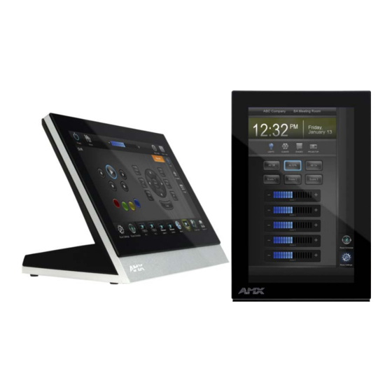
7" modero x series tabletop touch panel 7" modero x series wall/flush mount touch panel
Hide thumbs
Also See for MXT-700:
- Instruction manual (62 pages) ,
- Installation manual (2 pages) ,
- Quick start manual (2 pages)

Related Manuals for AMX MXT-700


Summary of Contents for AMX MXT-700
- Page 1 Operation/Reference Guide MXT/D-700 7" Modero X Series® Tabletop Touch Panel 7" Modero X Series® Wall/Flush Mount Touch Panel Touch Panels L a s t U p d a t e d : 1 0 / 9 / 2 0 1 3...
- Page 2 AMX is not responsible for products returned without a valid RMA number. AMX is not liable for any damages caused by its products or for the failure of its products to perform. This includes any lost profits, lost savings, incidental damages, or consequential damages.
- Page 3 LICENSE GRANT. AMX grants to Licensee the non-exclusive right to use the AMX Software in the manner described in this License. The AMX Software is licensed, not sold. This license does not grant Licensee the right to create derivative works of the AMX Software.
-
Page 5: Table Of Contents
Modero X Series Customer Benefits ................. 1 MXT-700 ........................2 Connector Locations......................4 Memory ........................... 4 Basic Operation ....................... 4 Powering on the MXT-700 ....................4 Microphone ........................5 Audio/Video Capabilities....................5 MXT-700-NC ......................5 MXD-700........................5 Memory ........................... 8 Basic Operation ....................... - Page 6 Table of Contents Uninstalling the MXD-700..................21 Configuration and Programming ..............23 Modero X Series Programming Guide ..............23 Upgrading Firmware ..................25 Overview ........................ 25 Upgrading Firmware via USB Flash Drive ............... 25 Load the Firmware on a USB Flash Drive ..............25 Transfer the Firmware File From the Flash Drive to the Touch Panel......
-
Page 7: Modero X Series Touch Panels
Modero X Series® Touch Panels ® Modero X Series Touch Panels Overview See more and do more with the most elegant interface designed specifically for dedicated room control. The Modero X ® Series Touch Panels provide several industry firsts, including a beautiful, panoramic capacitive multi-touch screen that provides users access to multiple applications with minimal navigation. - Page 8 FIG. 1 MXT-700 touch panel The MXT-700 features a 7.3" x 4.8" (186 mm x 122 mm), 8.8" (222 mm) diagonal display, with a viewable area of 6.05" x 3.54" (154 mm x 90 mm), 7.0" (178 mm) diagonal. The device communicates via Ethernet (10/100 port, RJ-45 connector, supported IP and IP-based protocols: UCP, TCP, ICMP, ICSP, IGMP, DHCP, Telnet, FTP, DNS, RFB for VNC, and HTTP) and USB (2 USB host 2.0, Type A ports).
- Page 9 Modero X Series® Touch Panels MXT-700 Specifications Power Requirements: PoE (Power over Ethernet), 802.3af, class 3 Power Consumption: • Full-On: 8W maximum • Standby: 3.2 W • Shutdown: 1 W Front Panel Components: NFC Transceiver: Antenna and transceiver for Near Field Communications device detection and interaction.
-
Page 10: Mxt-700
Basic Operation The MXT-700 is operated using its integral touchscreen, as well as the Sleep button on the top of the device (FIG. 1). If the device has gone into its Sleep Mode, a touch of the touchscreen or of the Sleep button will reactivate it. -
Page 11: Microphone
Audio/Video Capabilities The MXT-700 has the capability of displaying multiple JPEG and PNG files at one time. The device also supports streaming motion JPEG video (of the sort used by many IP and Web cameras), as well as MP3 and WAV audio files. - Page 12 Modero X Series® Touch Panels Sleep Button NFC Sensor FIG. 5 MXD-700 (Portrait Wall Mount) MXD-700 Specifications Power Requirements: PoE (Power over Ethernet), 802.3af, class 3 Power Consumption: • Full-On: 8W maximum • Standby: 3.2 W • Shutdown: 1 W Front Panel Components: NFC Transceiver: Antenna and transceiver for Near Field Communications device detection and...
-
Page 13: Mxd-700
Audio: Streaming/File Formats: WAV, MP3 Intercom: Full Duplex VoIP, SIP v2.0 (supported with AMX-CSG) Operating • Operating Temperature: 32° F to 104° F (0° C to 40° C) Environment: • Storage Temperature: 4° F to 140° F (-20° C to 60° C) •... -
Page 14: Memory
Modero X Series® Touch Panels MXD-700 Specifications (Cont.) Other AMX Equipment: • PS-POE-AF-TC, POE Injector, 802.3af Compliant (FG423-83) • MXA-BT Bluetooth USB Adaptor (FG5968-19) • CB-MXP7, Rough-In Box and Cover Plate for Modero X Series Touch Panel, 7" (FG039-18) • NXA-ENET8-2POE, Gigabit Switch, 8 Port POE, 2 Port SFP (FG2178-63) -
Page 15: Mxd/T-700 Features
Picture View By connecting a USB drive via one of the device’s USB ports (FIG. 3), Picture View allows the MXT-700 to access JPEG images on that drive and display them on the touchscreen (FIG. 7). Individual images may be accessed at any time, or the entire collection may be displayed for predetermined times. -
Page 16: Preview Mode And Normal Mode
Picture View goes into its Normal Mode when the MXT-700 goes into idle timeout while connected to a USB drive. Normal Mode displays images until the touchscreen is touched, or some other wakeup event is detected. When the device goes back into timeout, Normal Mode will return to displaying images until the USB drive is removed from the device. -
Page 17: Configuration
3.25" (82.55 mm) from the left corner of the panel and 0.375" (9.53 mm) from the top edge. When using an NFC device with the MXT-700, you should align your device’s antenna with the center of the touch panel’s antenna (FIG. -
Page 18: Installation
Power for the MXT-700 is supplied via Power Over Ethernet (PoE), utilizing an AMX-certified, capacitive touch- compliant PoE injector or other approved AMX PoE power source. The incoming Ethernet cable should be connected to the RJ45 port on the cable attached to the device (FIG. 10). - Page 19 FIG. 11 Bottom of the MXT-700 To disconnect and reconnect the MXT-700’s Ethernet cable to allow use of a hole smaller than 1.00” in diameter: On a soft surface, turn the MXT-700 face-down to access the bottom of the device.
-
Page 20: A Note About Wall And Rack Installation
FIG. 12 shows an AMX device installed in a wall with a filled volume (such as with insulation or concrete), as well as with a closed volume (such as between studs in an otherwise finished wall). The diagram shows how heat generated by the device or other devices may have no way to escape, and may build up to levels that may affect device operation. -
Page 21: Installation Recommendations
Power for the MXD-700 is supplied via Power Over Ethernet (PoE), utilizing an AMX-certified, capacitive touch- compliant PoE injector or other approved AMX PoE power source. The incoming Ethernet cable should be connected to the RJ45 port on the MXD-700 (FIG. 15 and FIG. 16). -
Page 22: Installing The Mxd-700 Into A Wall
Installation RJ45 Cable Clip RJ45 Port FIG. 16 Rear of the MXD-700 (with RJ45 connection extended) Installing the MXD-700 into a wall The MXD-700 comes with a clear plastic backbox (designed to attach the panel to most standard wall materials. This backbox has two locking tabs (one on top and one on bottom) to help lock the backbox to the wall. - Page 23 Installation The maximum recommended torque to screw in the locking tabs on the plastic back box is 5 IN-LB [56 N-CM]. Applying excessive torque while tightening the tab screws, such as with powered screwdrivers, can strip out the locking tabs or damage the plastic back box.
- Page 24 Installation Thread the incoming Ethernet from their terminal locations through the surface opening (FIG. 19). Leave enough slack in the wiring to accommodate any re-positioning of the panel. Mounting Surface Locking Back Box #4 Screws Knockouts FIG. 19 MXD-700 Back Box Installation (Landscape) Remove the back box knockouts (FIG.
- Page 25 Installation Test the incoming wiring by attaching the panel connections to their terminal locations and applying power. Verify that the panel is receiving power and functioning properly to prevent repetition of the installation. Do not disconnect the connectors from the touch panel. The unit must be installed with the attached connectors before being inserted into the mounting surface.
-
Page 26: Uninstalling The Mxd-700
Installation Uninstalling the MXD-700 The MXD-700 is held in place to the back box via latch hooks and clips on the back box (FIG. 21), securing it to the mounting surface. In certain circumstances, such as firmware updates or other maintenance that requires accessing the device’s USB port, the device may need to be removed from the back box. - Page 27 Installation MXD/T-700 7" Modero X Series® Touch Panels...
-
Page 28: Configuration And Programming
Configuration and Programming Configuration and Programming Programming the MXT-700 and MXD-700 require the use of the latest versions of NetLinx Studio and TPDesign 4, both available at www.amx.com. Modero X Series Programming Guide Information on Settings pages, panel configuration, and programming is included in the Modero X Series Programming Guide, available at www.amx.com. -
Page 29: Configuration And Programming
Configuration and Programming MXD/T-700 7" Modero X Series® Touch Panels... -
Page 30: Upgrading Firmware
Overview The latest firmware (*.kit) file for each panel is available to download from www.amx.com. To download firmware files, go to the catalog page for your panel type, and click the link under "Firmware Files" on the right side of the catalog page (FIG. -
Page 31: Transfer The Firmware File From The Flash Drive To The Touch Panel
After the upgrade, the unit contains the newly loaded version of firmware. Upgrading from Previous Firmware The MXT-700 and MXD-700 allow the option to revert the device to the previous firmware run before an upgrade. To upgrade the device from previously loaded firmware: From the Settings page, select the Configuration page. -
Page 32: Returning To Factory Default Firmware
If you choose Yes, the device will retrieve the files and then reboot. Returning to Factory Default Firmware The MXT-700 and MXD-700 allow the option to return the device to its original factory default firmware, which may be necessary in certain situations. To return the device to its factory default firmware: From the Settings page, select the Configuration page. -
Page 33: Upgrading Firmware Via Netlinx Studio
Upgrading Firmware Via NetLinx Studio The MXT-700 and MXD-700 use an Ethernet connection for programming, firmware updates, and touch panel file transfer via NetLinx Studio. If you have access to the panel’s network, you may transfer files directly to the panel... -
Page 34: Viewing Devices On The Virtual System
Upgrading Firmware Click the Edit Settings button on the Communications Settings dialog to open the Virtual NetLinx Master Settings dialog (FIG. 29). FIG. 29 Virtual NetLinx Master Settings Within this dialog, enter the Master System number. The default is 1. In the Available Connections section, click on the IP address for the touch panel to select it. -
Page 35: Downloading Firmware
Kit file. If the panel firmware version is not the latest available; locate the latest firmware file from www.amx.com. Click on the desired Kit file link and after accepting the Licensing Agreement, verify download of the Modero Kit file to a known location. - Page 36 Upgrading Firmware Verify you have downloaded the latest firmware file from www.amx.com and then save the Kit file to your computer. MXD/T-700 7" Modero X Series® Touch Panels...
- Page 37 Upgrading Firmware MXD/T-700 7" Modero X Series® Touch Panels...
-
Page 38: Appendix: Troubleshooting
Appendix: Troubleshooting Appendix: Troubleshooting Overview This section describes the solutions to possible hardware/firmware issues that could arise during the common operation of a Modero X touch panel. Panel Doesn’t Respond To Touches Symptom: The device either does not respond to touches on the touch screen or does not register the touch as being in the correct area of the screen. - Page 39 Appendix: Troubleshooting MXD/T-700 7" Modero X Series® Touch Panels...
- Page 40 Appendix: Troubleshooting MXD/T-700 7" Modero X Series® Touch Panels...
- Page 41 It’s Your World - Take Control™ 3000 RESEARCH DRIVE, RICHARDSON, TX 75082 USA • 800.222.0193 • 469.624.8000 • 469-624-7153 fax • 800.932.6993 technical support • www.amx.com...