3Com 3CRUS2475 User Manual
Unified gigabit wireless poe switch 24
Hide thumbs
Also See for 3CRUS2475:
- Quick start manual (40 pages) ,
- Declaration of conformity (1 page) ,
- Command reference manual (522 pages)

Related Manuals for 3Com 3CRUS2475


Summary of Contents for 3Com 3CRUS2475
-
Page 1: User Guide
® 3Com Unified Gigabit Wireless PoE Switch 24 User Guide 3CRUS2475 www.3Com.com Part No. 10015245 Rev. AA Published October 2006... -
Page 2: About This Guide
Software is delivered as “Commercial Computer Software” as defined in DFARS 252.227-7014 (June 1995) or as a “commercial item” as defined in FAR 2.101(a) and as such is provided with only such rights as are provided in 3Com’s standard commercial license for the Software. Technical data is provided with limited rights only as provided in DFAR 252.227-7015 (Nov 1995) or FAR 52.227-14 (June 1987), whichever is applicable. - Page 3 BOUT UIDE This guide provides information about the Web user interface for the 3Com® Unified Gigabit Wireless PoE Switch 24. The Embedded Web System (EWS) is a network management system. The Embedded Web Interface configures, monitors, and troubleshoots network devices from a remote web browser.
- Page 4 Configuring the Wizard — Provides information for configuring the ■ Setup wizard which enables system administrator configure basic device settings at the Setup stage or to return and reconfigure the device settings at any stage. Getting Started — Provides information for using the Embedded ■...
- Page 5 Classic, Rapid, and multiple Spanning Tree. Configuring Quality of Service — Provides information for Basic ■ and Advanced Quality of Service, including DSCP and CoS mapping, policies, and configuring Trust mode. Managing System Logs — Provides information for viewing system ■...
-
Page 6: Intended Audience
Intended Audience This guide is intended for network administrators familiar with IT concepts and terminology. If release notes are shipped with your product and the information there differs from the information in this guide, follow the instructions in the release notes. -
Page 7: Table Of Contents
User Guide Overview Intended Audience Conventions Related Documentation ONFIGURING THE IZARD Step 1 — Viewing Factory Defaults Step 2 — Configuring System Settings Step 3 — Configuring IP Settings Step 4 — Defining Wireless Settings Step 5 — Saving Configured Settings ETTING... - Page 8 Defining Multiple Hosts Modifying Multiple Hosts Managing Port Security Enabling Storm Control Configuring EAP Statistics Defining ACLs Configuring ACLs Defining MAC-based ACL Rules Removing MAC-based ACLs Defining IP-based ACLs Defining IP-based ACLs Defining IP-based ACLs Removing IP-based ACLs Binding ACLs...
- Page 9 Defining GVRP Defining Voice VLAN WLAN EFINING Defining Wireless Access Points Defining Wireless Security Configuring Wireless Access Point Security Defining Wireless Rogue Handling Mitigating Rogue Handling Defining Wireless Radio Settings Configuring Radio 802.11a Settings Defining Radio 802.11a Settings Managing VAPs...
- Page 10 Defining IGMP Snooping Enabling IGMP Snooping Defining Multicast Groups Defining Router Groups ONFIGURING PANNING Defining Classic Spanning Tree for Ports Configuring Classic Spanning Tree Modifying Spanning Tree Settings Defining Rapid Spanning Tree Modifying Rapid Spanning Tree Settings Defining Multiple Spanning Tree...
- Page 11 Defining CoS to Queue ANAGING YSTEM Viewing Logs Configuring Logging ANAGING YSTEM ILES Backing Up and Restoring System Files Downloading the Software Image Activating Image Files IEWING TATISTICS Viewing RMON Statistics Configuring RMON History Modifying RMON History Entries Removing RMON History Entries...
- Page 12 ONTENTS WLAN C OUNTRY ETTINGS EVICE PECIFICATIONS AND EATURES Related Standards Environmental Physical Electrical Unified Switch 24 Features ROUBLESHOOTING Problem Management Troubleshooting Solutions LOSSARY NDEX...
-
Page 13: Onfiguring The Wizard
Step 5 — Saving Configured Settings ■ Step 1 — Viewing The Welcome to the Setup Wizard Page is the first step in the wizard and Factory Defaults it displays a summary of factory default settings. The table displays three sets of settings: System parameters, IP configuration and Wireless configuration. - Page 14 IP Configuration — Displays parameters for assigning IP addresses. ■ Packets are forwarded to the default IP when frames are sent to a remote network. The IP Configuration parameters are manually configured in Step 3. The section includes the following fields: Method —...
- Page 15 ■ selected WLAN security method. WEP provides the same security level as a wired LAN. WEP encrypts data over radio waves during the packet transmission. WEP keys are 40 bit or 104 bit encryption keys. WPA-PSK — Indicates that Wi-Fi Protected Access (WPA) is the ■...
-
Page 16: Step 2 - Configuring System Settings
System Location — Defines the location where the system is ■ currently running. The field range is 0-160 characters. System Contact — Defines the name of the contact person. The field ■ range is 0-160 characters. 3 Define the fields. -
Page 17: Step 3 - Configuring Ip Settings
Configuration Method — Indicates if the IP address has been ■ configured statically or added dynamically. The possible field values are: Manual — Indicates that the IP Interface is configured by the user. ■ DHCP — Indicates that the IP Interface is dynamically created. ■... -
Page 18: Step 4 - Defining Wireless Settings
SSID Name — Displays the Service Set Identifier SSID for the ESS. ■ SSIDs act as a password when a mobile device attempts to connect to the BSS. SSIDs differentiate between WLANs, therefore all access points and devices which comprise the specific WLAN must have the same SSID. -
Page 19: Step 5 - Saving Configured Settings
Step 5 — Saving Configured Settings Protocol (TKIP). In addition, WPA improves authentication using EAP. EAP ensures that only authorized network users access the network though secure encryption systems. WPA2-PSK — Indicates that WPA2-PSK is the selected WLAN ■ security method. WPA2-PSK improves system security by encrypting signals at a higher bit rates. -
Page 20: Getting Started
2 Ensure that pop-up blockers are disabled. If pop-up blockers are enable, edit, add, and device information messages may not open. 3 Enter the device IP address in the address bar and press Enter. The Enter Network Password Page opens:... - Page 21 Figure 6 Enter Network Password Page 4 Enter your user name and password. The device is configured with a user name that is admin and a password that is blank, and can be configured without entering a password. Passwords are case sensitive.
-
Page 22: Understanding The 3Com Embedded Web Interface
Web Interface Tab View — Tab Area provides the device summary configuration ■ located at the top of the home page, the tab view contains a Setup Wizard and the Summary, Wired and Wireless configuration views. Tree View — Tree View provides easy navigation through the ■... - Page 23 2 Tab View The Tab Area enables navigation through the different device features. Click the tabs to view all the components under a specific feature. 3 3Com Web Interface Informa- Provide access to online help, and contain information about the EWS.
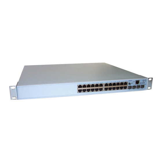
- Page 24 1 Click Device Summary > Wired. Figure 9 Device Representation 2 By selecting a specific port with your mouse, you can either choose to configure the port settings or view the port statistics. For detailed information on configuring ports, please refer to Section 6 Configuring Wired Ports.
-
Page 25: Using Screen And Table Options
Using Screen and Table Options Using Screen and 3Com contains screens and tables for configuring devices. This section Table Options contains the following topics: Viewing Configuration Information ■ Adding Configuration Information ■ Modifying Configuration Information ■ Removing Configuration Information ■... - Page 26 ETTING TARTED Viewing Configuration Information To view configuration information: 1 Click Wired Ports > Port Settings > Summary. The Port Settings Summary Page opens: Figure 10 Port Settings Summary Page Adding Configuration Information User-defined information can be added to specific 3Com Web Interface pages, by opening a Setup page.
- Page 27 Using Screen and Table Options Figure 11 Password Management Setup Page 2 Define the fields. 3 Click . The configuration information is saved, and the device is updated.
- Page 28 2: G HAPTER ETTING TARTED Modifying Configuration Information 1 Click Wired Ports > LACP > Modify. A modification page, such as the LACP Modify Page opens: Figure 12 LACP Modify Page 2 Modify the fields. 3 Click . The fields are modified, and the information is saved to the...
- Page 29 1 Click Administration > Management Access > Remove. The Management Access [Remove] Page opens: Figure 13 Management Access [Remove] Page 2 Select the management method to be deleted. 3 Click . The Management Method is deleted, and the device is updated.
-
Page 30: Saving The Configuration
2: G HAPTER ETTING TARTED Saving the The Save Configuration tab allows the latest configuration to be saved to Configuration the flash memory. To save the device configuration: 1 Click Save Configuration. The Save Configuration Page opens: Figure 14 Save Configuration Page A message appears: The operation will save your configuration. -
Page 31: Restoring Factory Defaults
2 Click . A confirmation message is displayed. 3 Click . The device is reset, and a prompt for a user name and password is displayed. 4 Enter a user name and password to reconnect to the web interface. Restoring Factory The Restore option appears on the Reset page. -
Page 32: Logging Off The Device
2: G HAPTER ETTING TARTED To Restore the device: 1 Click Administration > Reset. The Reset Page opens: Figure 16 Reset Page 2 Click . The system is restored to factory defaults. Logging Off the To log off the device:... -
Page 33: Viewing Basic Settings
This section contains information for viewing basic settings. The 3Com Embedded Web Interface Home Page presents a device summary section that provides the system administrator with the option to view and configure essential information required for setting up and maintaining device settings. -
Page 34: Viewing Device Settings
System Location — Defines the location where the system is ■ currently running. The field range is 0-160 characters. System Contact — Defines the name of the contact person. The field ■ range is 0-160 characters. Serial Number — Displays the device serial number. -
Page 35: Viewing Wired Settings
The Device Summary Wired Page displays port LED Indicators that include Settings port status and basic port settings. The port status is presented with a color scheme that is described in the following table. The system administrator can view the port settings by scrolling over the relevant port... - Page 36 ■ connections which are the physical interface used for terminating twisted pair type cable. SFP — Displays the port status of the Small Form Factor (SFP) optical ■ transmitter modules that combine transmitter and receiver functions. The table includes the color and the port status: White —...
-
Page 37: Viewing Wireless Settings
Viewing Wireless Settings Light Gray — Port has been set to inactive by User or ■ Protocol. Dark Blue — Port has been selected by user. ■ Red — Port or Transceiver has failed POST or Transceivers not ■ recognized. - Page 38 54 mbps. b/g — Indicates the radio type is 802.11b/g. ■ n — Indicates the radio type that is based on MIMO (Multiple ■ input, multiple output) technology, which uses multiple antennas at both the source (transmitter) and the destination (receiver) to minimize errors and optimize data speed.
-
Page 39: Anaging Evice Ecurity
ANAGING EVICE ECURITY This section provides access to security pages that contain fields for setting security parameters for ports, device management methods, users, and server security. This section contains the following topics: Configuring Management Security ■ Configuring Network Security ■... - Page 40 Assigning an access profile to an interface denies access via other interfaces. If an access profile is assigned to any interface, the device can be accessed by all interfaces. To view Management Access: 1 Click Administration >...
- Page 41 HTTP meeting access profile criteria are permitted or denied access to the device. Secure HTTP (SSL) — Assigns SSL access to the rule. If selected, ■ users accessing the device using SSL meeting access profile criteria are permitted or denied access to the device.
- Page 42 Network Mask — Determines what subnet the source IP Address ■ belongs to in the network. Prefix Length — Defines the number of bits that comprise the source ■ IP address prefix, or the network mask of the source IP address.
- Page 43 Management Access applies. The Source IP Address field is valid for a subnetwork. Prefix Length — Defines the number of bits that comprise the source ■ IP address prefix, or the network mask of the source IP address.
-
Page 44: Configuring Password Management
The Password Management Summary Page contains the following fields: User Name — Displays the user name. ■ Access Level — Displays the user access level. The lowest user access ■ level is Monitoring and the highest is Configuration. Configuration — Provides the user with read and write access ■... - Page 45 The Password Management Setup Page contains the following fields: User Name — Displays the user name. ■ Access Level — Displays the user access level. The lowest user access ■ level is Monitoring and the highest is Configuration. Configuration — Provides users read and write access rights.
- Page 46 The Password Management Modify Page contains the following fields: User Name — Displays the user name. ■ Access Level — Displays the user access level. The lowest user access ■ level is Monitoring and the highest is Configuration. Configuration — Provides users read and write access rights.
- Page 47 Remove. The Password Management Remove Page opens: Figure 26 Password Management Remove Page The Password Management Remove Page contains the following fields: Remove — Removes the user from the User Name list. The possible ■ field values are: Checked — Removes the selected local user.
-
Page 48: Defining Radius Authentication
The default parameters are user-defined, and are applied to newly defined RADIUS servers. If new default parameters are not defined, the system default values are applied to newly defined RADIUS servers. To configure RADIUS Servers: 1 Click Administration >... - Page 49 Possible field values are 1-30. The default value is 3. Dead Time — Defines the default amount of time (in minutes) that a ■ RADIUS server is bypassed for service requests. The range is 0-2000.
-
Page 50: Defining Tacacs+ Authentication
TACACS+ server. The TACACS+ default parameters are user-assigned defaults. The default settings are applied to newly defined TACACS+ servers. If default values are not defined, the system defaults are applied to the new TACACS+ new servers. - Page 51 Authentication Port (0-65535) — Defines the port number via ■ which the TACACS+ session occurs. The default port is port 49. Timeout for Reply — Defines the default time that passes before the ■ connection between the device and the TACACS+ times out. The default is 5.
- Page 52 3: M HAPTER ANAGING EVICE ECURITY Checked — Enables a single connection. ■ Unchecked — Disables a single connection. ■ 2 Define the fields. 3 Click . The TACACS+ Server is enabled, and the device is updated.
-
Page 53: Configuring Network Security
Configuring Network Security Configuring Network The Network Security section provides links that enable you to configure Security Port-based authentication, port security, storm control and EAP statistics. This section includes the following: Port-based Authentication ■ Advanced Port-based Authentication ■ Managing Port Security ■... - Page 54 ECURITY Configuring Port Authentication Settings To configure 802.1x Global Settings: 1 Click Policy > Security > 802.1x Global Settings > Setup. The 802.1x Global Settings Setup Page opens: Figure 29 802.1x Global Settings Setup Page 802.1x Global Settings Setup Page contains the following fields: Port-based Authentication State —...
- Page 55 802.1x Global Settings updated. To view Port-based Authentication: 1 Click Policy > Security > Port Authentication > Summary. The Port Authentication Summary Page opens: Figure 30 Port Authentication Summary Page The Port Authentication Summary Page contains the following fields: Copy from Entry Number —...
- Page 56 Reauthentication Period — Displays the time span (in seconds) in ■ which the selected port is reauthenticated. The field default is 3600 seconds. The field range is 300-4294967295 seconds. Termination Cause — Displays the reason for which the port ■...
- Page 57 ForceUnauthorized — Indicates that either the port control is force ■ Unauthorized and the port link is down, or the port control is Auto but a client has not been authenticated via the port. ForceAuthorized — Indicates that the port control is Forced ■...
-
Page 58: Advanced Port-Based Authentication
Authentication attached to a single port. Advanced port-based authentication requires only one host to be authorized for all hosts to have system access. If the port is unauthorized, all attached hosts are denied access to the network. Advanced port-based authentication also enables user-based authentication. -
Page 59: Viewing Authenticated Hosts
Multiple Host Mode — Multiple hosts can be attached to a single ■ port. Only one host must be authorized for all hosts to access the network. If the host authentication fails, or an EAPOL-logoff message is received, all attached clients are denied access to the network. - Page 60 User Name — Lists the supplicants that were authenticated, and are ■ permitted on each port. ■ Session Time — Displays the amount of time (in seconds) the supplicant ■ was logged on the port. Authentication Method — Displays the method by which the last session ■...
-
Page 61: Defining Multiple Hosts
Hosts advanced port-based authentication settings for specific ports and VLANs. To view Multiple Hosts: 1 Click Policy > Security > Multiple Host > Summary. The Multiple Host Summary Page opens: Figure 33 Multiple Host Summary Page The Multiple Host Summary Page contains the following fields: Port —... -
Page 62: Modifying Multiple Hosts
The Trap Frequency field can be defined only if multiple hosts are disabled. The field range is 1-1,000,000. The default is 10 seconds. Status — Indicates the host status. If there is an asterisk (*), the port ■ is either not linked or is down. The possible field values are: Number of Violations —... - Page 63 Modifying Multiple Hosts To modify Multiple Hosts: 1 Click Policy > Security > Multiple Host > Modify. The Multiple Host Modify Page opens: Figure 34 Multiple Host Modify Page The Multiple Host Modify Page contains the following fields: Port — Displays the port number for which advanced port-based ■...
-
Page 64: Managing Port Security
These addresses are either manually defined on the port, or learned on that port up to the point when it is locked. When a packet is received on a locked port, and the packet source MAC address is not tied... - Page 65 Managing Port Security To view Port Security: 1 Click Policy > Security > Port Security > Summary. The Port Security Summary Page opens: Figure 35 Port Security Summary Page The Port Security Summary Page contains the following fields: Interface — Displays the port or LAG name.
- Page 66 Max Entries — Specifies the number of MAC address that can be ■ learned on the port. The Max Entries field is enabled only if Locked is selected in the Set Port field. In addition, the Limited Dynamic Lock mode is selected. The field range is 1- 128. The default is 1.
- Page 67 Managing Port Security To modify Port Security: 1 Click Policy > Security > Port Security > Modify. The Port Security Modify Page opens: Figure 36 Port Security Modify Page The Port Security Modify Page contains the following fields: Interface — Displays the port or LAG name.
-
Page 68: Enabling Storm Control
Max Entries — Specifies the number of MAC address that can be ■ learned on the port. The Max Entries field is enabled only if Locked is selected in the Set Port field. In addition, the Limited Dynamic Lock mode is selected. The field range is 1- 128. The default is 1. - Page 69 Enabling Storm Control To view Storm Control Traffic: 1 Click Policy > Storm Control > Summary. The Storm Control Summary Page opens: Figure 37 Storm Control Summary Page The Storm Control Summary Page contains the following fields: Copy from Entry Number — Copies the storm control parameters ■...
- Page 70 The Storm Control Modify Page provides fields for configuring broadcast storm control. To modify Storm Control Settings: 1 Click Policy > Storm Control > Modify. The Storm Control Modify Page opens: Figure 38 Storm Control Modify Page The Storm Control Modify Page contains the following fields: Port —...
-
Page 71: Configuring Eap Statistics
The EAP Statistics Summary Page contains information about EAP packets Statistics received on a specific port. To view EAP Statistics: 1 Click Policy > Security > EAP Statistics. The EAP Statistics Summary Page opens: Figure 39 EAP Statistics Summary Page The EAP Statistics Summary Page contains the following fields:... - Page 72 Port — Displays the port number for which advanced port-based ■ authentication is enabled. Refresh Rate — Defines the amount of time that passes before the ■ statistics are refreshed. The possible field values are: 15 Sec—Indicates that the statistics are refreshed every 15 ■...
-
Page 73: Defining Acls
Packets entering an ingress port, with an active ACL, are either admitted or denied entry and the ingress port is disabled. If they are denied entry, the user can disable the port. - Page 74 ECURITY Viewing MAC-based To view MAC-based ACLs: ACLs 1 Click Policy > ACL > MAC Based ACL > ACL Summary. The MAC-based ACL Summary Page opens: Figure 40 MAC-based ACL Summary Page The MAC-based ACL Summary Page contains the following fields: Priority —...
- Page 75 Permit — Forwards packets which meet the ACL criteria. ■ Deny — Drops packets which meet the ACL criteria. ■ Shutdown — Drops packet that meet the ACL criteria, and disables ■ the port to which the packet was addressed. Ports are reactivated from the Interface Configuration Page.
-
Page 76: Configuring Acls
HAPTER ANAGING EVICE ECURITY Configuring ACLs 1 Click Policy > ACL > MAC Based ACL > ACL Setup. The ACL Setup Page opens: Figure 41 ACL Setup Page The ACL Setup Page contains the following fields: ACL Name — Contains a list of the MAC-based ACLs. - Page 77 Destination Wild Card Mask — Indicates the destination MAC ■ Address wild card mask. Wild cards are used to mask all or part of a destination MAC address. Wild card masks specify which bits are used and which are ignored. A wild card mask of FF:FF:FF:FF:FF indicates that no bit is important.
-
Page 78: Defining Mac-Based Acl Rules
ECURITY Defining MAC-based To define MAC-based ACL Rules: ACL Rules 1 Click Policy > ACL > MAC Based ACL > Rule Setup. The MAC-based ACL Rule Setup Page opens: Figure 42 MAC-based ACL Rule Setup Page The MAC-based ACL Rule Setup Page contains the following fields: ACL Name —... - Page 79 Destination Wild Card Mask — Indicates the destination MAC ■ Address wild card mask. Wild cards are used to mask all or part of a destination MAC address. Wild card masks specify which bits are used and which are ignored. A wild card mask of FF:FF:FF:FF:FF indicates that no bit is important.
-
Page 80: Removing Mac-Based Acls
ECURITY Removing To remove MAC-based Class Maps: MAC-based ACLs 1 Click Policy > ACL > MAC Based ACL > Remove. The MAC-based ACL Remove Page opens: Figure 43 MAC-based ACL Remove Page The MAC-based ACL Remove Page contains the following fields: ACL Name —... - Page 81 Ports are reactivated from the Interface Configuration Page. 2 Select the ACL Name to be deleted. 3 Enable ACL Removal and select the ACL to be removed from the table. 4 Click the Remove Checkbox. The ACL is removed. 5 Click .
-
Page 82: Defining Ip-Based Acls
The IP Based ACL Page contains information for defining IP-based ACLs, ACLs including defining the ACEs defined for IP-based ACLs. To view IP-based Class Maps: 1 Click Policy > ACL > IP Based ACL > ACL Summary. The IP-based ACL Summary Page opens: Figure 44 IP-based ACL Summary Page The IP-based ACL Summary Page contains the following fields: ACL Name —... - Page 83 DSCP —Matches the packet DSCP value to the ACL. Either the DSCP ■ value or the IP Precedence value is used to match packets to ACLs. The possible field range is 0-63. IP - Prec. — Indicates matching ip-precedence with the packet ■...
-
Page 84: Defining Ip-Based Acls
ECURITY Defining IP-based To configure IP-based Class Maps: ACLs 1 Click Policy > ACL > IP Based ACL > ACL Setup. The IP-based ACL Setup Page opens: Figure 45 IP-based ACL Setup Page The IP-based ACL Setup Page contains the following fields: ACL Name —... - Page 85 Destination Wild Card Mask — Indicates the destination IP Address ■ wild card mask. Wild cards are used to mask all or part of a destination IP Address. Wild card masks specify which bits are used and which bits are ignored. A wild card mask of 255.255.255.255 indicates that no bit is important.
- Page 86 Match IP Precedence — Matches the packet IP Precedence value to ■ the ACE. Either the DSCP value or the IP Precedence value is used to match packets to ACLs. Action — Indicates the ACL forwarding action. Possible field values ■...
-
Page 87: Defining Ip-Based Acls
Defining IP-based ACLs Defining IP-based To configure IP-based Rules: ACLs 1 Click Policy > ACL > IP Based ACL > Rule Setup. The IP-based ACL Rule Setup Page opens: Figure 46 IP-based ACL Rule Setup Page The IP-based ACL Rule Setup Page contains the following fields: ACL Name —... - Page 88 Wild Card Mask — Indicates the destination IP Address wild card ■ mask. Wild cards are used to mask all or part of a destination IP Address. Wild card masks specify which bits are used and which bits are ignored. A wild card mask of 255.255.255.255 indicates that no bit is important.
- Page 89 Defining IP-based ACLs Shutdown — Drops packet that meet the ACL criteria, and disables ■ the port to which the packet was addressed. Ports are reactivated from the Interface Configuration Page. 2 Select an ACL from the ACL Name drop-down list.
-
Page 90: Removing Ip-Based Acls
Removing IP-based To remove IP-based ACL: ACLs 1 Click Policy > ACL > IP Based ACL > Remove ACL. The IP-based ACL Remove Page opens: Figure 47 IP-based ACL Remove Page The IP-based ACL Remove Page contains the following fields: ACL Name —... - Page 91 IGMP Type — IGMP packets can be filtered by IGMP message type. ■ DSCP — Matches the packet DSCP value to the ACL. Either the DSCP ■ value or the IP Precedence value is used to match packets to ACLs.
-
Page 92: Binding Acls
EVICE ECURITY Binding ACLs To define ACL Binding: 1 Click Policy > ACL > ACL Binding > Binding Summary. The ACL Binding Summary Page opens: Figure 48 ACL Binding Summary Page The ACL Binding Summary Page contains the following fields: Ports —... - Page 93 Binding ACLs To define ACL Binding: 1 Click Policy > ACL > ACL Binding > Binding Setup. The ACL Binding Setup Page opens: Figure 49 ACL Binding Setup Page The ACL Binding Setup Page contains the following fields: Interface — Selects the Ports or LAGs interface to be configured.
-
Page 94: Managing System Information
ANAGING YSTEM NFORMATION This section contains information for configuring general system information, and includes the following: Viewing System Description ■ Defining System Settings ■ Configuring Country Codes ■ Configuring System Name ■ Configuring System Time ■ Saving the Device Configuration... -
Page 95: Viewing System Description
System Location — Defines the location where the system is ■ currently running. The field range is 0-160 characters. System Contact — Defines the name of the contact person. The field ■ range is 0-160 characters. Serial Number — Displays the device serial number. - Page 96 MAC Address — Displays the device MAC address. ■ System Up Time — Displays the amount of time since the most ■ recent device reset. The system time is displayed in the following format: Days, Hours, Minutes, and Seconds.
-
Page 97: Defining System Settings
Defining System Settings Defining System The following section allows system administrators to configure advanced Settings system settings. The section includes the following: Configuring Country Codes ■ Configuring System Name ■ Configuring System Time ■... -
Page 98: Configuring Country Codes
ANAGING YSTEM NFORMATION Configuring Defines the country code by which WLAN settings are set. For the Country Codes complete list of country codes and settings, see WLAN Country Settings. To configure the Country Code: 1 Click Administration > Country Code. The Country Codes Page opens:... - Page 99 Point Channels Antenna Gain = Frequency Country Code Domain Allowed EIRP) Range (GHz) Austria 36, 40, 44, 48 60 mW EIRP 5.15-5.25 1 - 11 100 mW EIRP 2.4-2.4835 Australia 36, 40, 44, 200 mW EIRP 5.15-5.25 48,52, 56, 60, 5.25-5.35...
- Page 100 Code Domain Allowed EIRP) Range (GHz) Czech Republic 36, 40, 44, 200 mW EIRP200 5.15-5.255.25-5 48,52, 56, 60, mW EIRP1 W EIRP .355.725-5.825 64,149, 153, 157, 161 1-11 200 mW EIRP 2.4-2.4835 Germany 36, 40, 44, 200 mW EIRP200 5.15-5.255.25-5...
- Page 101 Allowed EIRP) Range (GHz) France 36, 40, 44, 200 mW EIRP200 5.15-5.255.25-5 48,52, 56, 60, mW EIRP 1 - 7,8 - 11 100 mW EIRP100 2.4-2.48352.4-2 mW EIRP .454 United Kingdom 36, 40, 44, 200 mW EIRP200 5.15-5.25 48,52, 56, 60, mW EIRP1 W EIRP 5.25-5.35...
- Page 102 100 mW EIRP 2.4-2.4835 India 4 W EIRP 2.4-2.4835 Iceland 36, 40, 44, 200 mW EIRP200 5.15-5.25 48,52, 56, 60, mW EIRP1 W EIRP 5.25-5.35 5.47-5.725 64,104, 108, 112, 116, 120, 124, 128, 132, 1-11 100 mW EIRP 2.4-2.4835 Italy...
- Page 103 W 1-11 1 W+Restricted 2.4-2.4835 Antennas Luxembourg 36, 40, 44, 200 mW EIRP200 5.15-5.25 48,52, 56, 60, mW EIRP1 W EIRP 5.25-5.35 5.47-5.725 64,104, 108, 112, 116, 120, 124, 128, 132, 1-11 100 mW EIRP 2.4-2.4835 Latvia 36, 40, 44, 50 mW+6 dBi=200 5.15-5.25...
- Page 104 W 1-11 1 W+Restricted 2.4-2.4835 Antennas Philippines 5.725-5.875 100 mW EIRP 2.4-2.4835 Poland 36, 40, 44, 200 mW EIRP 1 W 2.4-2.4835 48,52, 56, 60, EIRP 64,149, 153, 157, 161 1-11 100 mW EIRP 2.4-2.4835 Portugal 36, 40, 44, 200 mW EIRP200 5.15-5.25...
- Page 105 Code Domain Allowed EIRP) Range (GHz) Sweden 36, 40, 44, 200 mW EIRP200 5.15-5.25 48,52, 56, 60, mW EIRP1 W EIRP 5.25-5.35 5.47-5.725 64,104, 108, 112, 116, 120, 124, 128, 132, 1-11 100 mW EIRP 2.4-2.4835 Singapore 36, 40, 44, 48, 200 mW EIRP200 5.15-5.25...
- Page 106 4: M HAPTER ANAGING YSTEM NFORMATION Maximum Transmit Power Access (Radio Tx + Country Point Channels Antenna Gain = Frequency Country Code Domain Allowed EIRP) Range (GHz) 1-13 1 W EIRP 2.4-2.4835 United States 36, 40, 44, 50 mW+6 dBi=200 5.15-5.25...
-
Page 107: Configuring System Name
System Location — Defines the location where the system is ■ currently running. The field range is 0-160 characters. System Contact — Defines the name of the contact person. The field ■ range is 0-160 characters. 2 Define the fields. -
Page 108: Configuring System Time
March. During the period of Daylight Saving Time, Brazilian clocks go forward one hour in most of the Brazilian southeast. Chile — In Easter Island, from March 9 until October 12. In the rest of ■ the country, from the first Sunday in March or after 9th March. - Page 109 Denmark — From the last weekend of March until the last weekend ■ of October. Egypt — From the last Friday in April until the last Thursday in ■ September. Estonia — From the last weekend of March until the last weekend of ■...
- Page 110 Macedonia — From the last weekend of March until the last ■ weekend of October. Mexico — From the first Sunday in April at 02:00 to the last Sunday ■ in October at 02:00. Moldova — From the last weekend of March until the last weekend ■...
- Page 111 Configuring System Time Taiwan — Taiwan does not use Daylight Saving Time. ■ Turkey — From the last weekend of March until the last weekend of ■ October. United Kingdom — From the last weekend of March until the last ■...
- Page 112 HAPTER ANAGING YSTEM NFORMATION for Paris is GMT +1, while the Time Zone Offset for New York is GMT –5. Daylight Savings — Enables automatic Daylight Savings Time (DST) ■ on the device based on the device’s location. There are two types of daylight settings, either by a specific date in a particular year or a recurring setting irrespective of the year.
-
Page 113: Saving The Device Configuration
Saving the Device Configuration Saving the Device The Save Configuration tab allows the latest configuration to be saved to Configuration the flash memory. To save the device configuration: 1 Click Save Configuration. The Save Configuration Page opens: Figure 54 Save Configuration Page The following message displays: The operation will save your configuration. -
Page 114: Resetting The Device
ANAGING YSTEM NFORMATION Resetting the The Reset page enables resetting the device from a remote location. Device To prevent the current configuration from being lost, save all changes from the running configuration file to the startup configuration file before resetting the device. - Page 115 ONFIGURING IRED ORTS This section contains information for configuring Port Settings, and includes the following sections: Viewing Port Settings ■ Defining Port Settings ■ Configuring Address Tables ■ Viewing Static Addresses ■ Defining Static Addresses ■ Viewing Dynamic Addresses ■...
-
Page 116: Configuring Wired Ports
■ Down — Indicates the port is currently not operating. ■ Port Speed — Displays the configured rate for the port. The port type ■ determines what speed setting options are available. Port speeds can only be configured when auto negotiation is disabled. The possible... - Page 117 ■ configurable only when auto negotiation is disabled, and the port speed is set to 10M or 100M or 1000M per second. This field cannot be configured on LAGs. The possible field values are: Full — The interface supports transmission between the device and ■...
- Page 118 ONFIGURING IRED ORTS wired, so that when a hub or switch is connected to an end station, a straight through Ethernet cable can be used, and the pairs are matched up properly. When two hubs or switches are connected to each other, or two end stations are connected to each other, a crossover cable is used to ensure that the correct pairs are connected.
-
Page 119: Defining Port Settings
The Port Settings Setup Page allows network managers to configure port Settings parameters for specific ports. To configure Port Settings: 1 Click Wired Ports> Port Settings > Setup. The Port Settings Setup Page opens: Figure 56 Port Settings Setup Page The Port Settings Setup Page contains the following fields: Port —... - Page 120 ■ configurable only when auto negotiation is disabled, and the port speed is set to 10M or 100M. This field cannot be configured on LAGs. The possible field values are: Full — The interface supports transmission between the device and ■...
- Page 121 ■ switches are deliberately wired opposite the way end stations are wired, so that when a hub or switch is connected to an end station, a straight through Ethernet cable can be used, and the pairs are matched up properly. When two hubs or switches are connected to each other, or two end stations are connected to each other, a crossover cable is used to ensure that the correct pairs are connected.
-
Page 122: Configuring Address Tables
. Addresses are associated with ports by learning the ports from the frames source address. Frames addressed to a destination MAC address that is not associated with any port, are flooded to all ports of the relevant VLAN. Static addresses are manually configured. In order to prevent the bridging table from overflowing, dynamic MAC addresses, from which no traffic is seen for a certain period, are erased. -
Page 123: Defining Static Addresses
MAC Address — The MAC addresses listed in the current static ■ addresses list. Interface — The specific port or LAG to which the static MAC address ■ is applied. Status — Displays the MAC address status. Possible values are: ■... - Page 124 In addition, several MAC Addresses can be defined for a single port. To open the Figure 58: 1 Click Wired Ports > Address Tables > Static Addresses > Setup. The Static Addresses Setup Page opens: Figure 58 Static Addresses Setup Page The Static Addresses Setup Page contains the following fields: Interface —...
-
Page 125: Removing Static Addresses
Removing Static Addresses Permanent — The MAC address is permanent. ■ Delete on Reset — The MAC address is deleted when the device is ■ reset. Delete on Time out —The MAC address is deleted when a timeout ■ occurs. - Page 126 ■ Unchecked — Maintains the current static address entries. ■ VLAN ID — The VLAN ID attached to the MAC Address, and a VLAN ■ called a Routed Interface.Routed Interfaces are the internally-used VLANs assigned to an port or trunk on which an IP address is configured.
-
Page 127: Viewing Dynamic Addresses
The Dynamic MAC Address Summary Page contains the following fields: Aging Interval (10-630) — Specifies the amount of time the MAC ■ Address remains in the Dynamic MAC Address before it is timed out if no traffic from the source is detected. The default value is 300 seconds. - Page 128 Interface — Specifies the interface for which the table is queried. ■ There are two interface types from which to select. MAC Address — Specifies the MAC address for which the table is ■ queried. VLAN ID — The VLAN ID for which the table is queried.
-
Page 129: Aggregating Ports
■ The device supports up to 64 LAGs, and eight ports in each LAG. ■ Ports can be configured as LACP ports only if the ports are not part of ■ a previously configured LAG. Ports added to a LAG lose their individual port configuration. When ■... -
Page 130: Configuring Lacp
Defining Link Aggregation ■ Configuring LACP LAGs can contain different media types if the ports are operating at the same speed. Aggregated links can be set up manually or automatically established by enabling LACP on the relevant links. Aggregate ports can be linked into link-aggregation port-groups. - Page 131 Specifies a short timeout value. ■ To modify LACP for LAGs: 1 Click Wired Ports > LACP > Modify. The “LACP Modify Page” opens: Figure 62 LACP Modify Page The LACP Modify Page contains the following fields: Port — Displays the port number to which timeout and priority values ■...
-
Page 132: Defining Link Aggregation
■ Defining LAG Membership ■ Configuring Link The Link Aggregation Page optimizes port usage by linking a group of Aggregation ports together to form a single LAG. Aggregating ports multiplies the bandwidth between the devices, increases port flexibility, and provides link redundancy. - Page 133 ■ Operates when the LAG is in full duplex mode. To configure Link Aggregation: 1 Click Wired Ports > Link Aggregation > Setup. The Link Aggregation Setup Page opens: Figure 64 Link Aggregation Setup Page The Link Aggregation Setup Page includes the following pages: LAG —...
- Page 134 Max Capability — Indicates that all LAG speeds and duplex mode ■ settings are accepted. 10 Full — Indicates that the LAG advertises for a 10 Mbps speed ■ LAG and full duplex mode setting. 100 Full — Indicates that the LAG advertises for a 100 Mbps speed ■...
- Page 135 ■ Current Speed — Displays the current LAG speed. ■ Admin Flow Control — Displays the flow control status on the LAG. ■ Operates when the LAG is in full duplex mode. Current Flow Control — Displays the current flow control status on ■...
-
Page 136: Defining Lag Membership
LAG Name — Displays the LAG name. ■ LACP — Displays the link operational status. ■ Port List — Displays the ports that can be assigned or removed from ■ the LAG membership list. LAG Members — Displays the ports which are currently configured ■... - Page 137 Defining LAG Membership...
-
Page 138: Configuring Vlans
VLANs function at Layer 2. Since VLANs isolate traffic within the VLAN, a Layer 3 router working at a protocol level is required to allow traffic flow between VLANs. Layer 3 routers identify segments and coordinate with VLANs. - Page 139 Defining Voice VLAN ■ Defining GVRP ■...
-
Page 140: Defining Vlan Properties
The VLAN Setup Summary provides information and global parameters Properties on VLANS configured on the system. To view VLANs: 1 Click Policy > VLAN > Setup > Summary. The VLAN Setup Summary Page opens: Figure 66 VLAN Setup Summary Page... - Page 141 ■ VLAN ID. The Setup Page creates VLANS on the system. To create VLANs: 1 Click Policy > VLAN > Setup > Setup. The VLAN Setup [Setup]Page opens: Figure 67 VLAN Setup [Setup]Page The Setup Page contains the following fields: VLAN ID —...
- Page 142 3 Click . The VLANs are configured, and the device is updated. To edit VLAN Settings: 1 Click Policy > VLAN > Setup > Modify. The “Modify VLAN Page” opens: Figure 68 Modify VLAN Page The Modify VLAN Page contains the following fields: VLAN ID —...
- Page 143 Defining VLAN Properties To delete VLANs: 1 Click Policy > VLAN > Setup > Remove. The “VLAN Remove Page” opens: Figure 69 VLAN Remove Page The VLAN Remove Page contains the following fields: Remove — Removes a specific VLAN. The possible field values are: ■...
-
Page 144: Defining Vlan Membership
7: C VLAN HAPTER ONFIGURING Defining VLAN The VLAN Membership Summary Page contains a table that maps VLAN Membership parameters to ports. Ports are assigned VLAN membership by toggling through the Port Control settings. To define VLAN Membership: 1 Click Policy > VLAN > Membership > Summary. The VLAN... - Page 145 Defining VLAN Membership LAG — Indicates the LAG membership. ■ Interface — Displays the port or LAG number included in the VLAN. ■ Interface Status— Displays the port-based for each Interface. ■ The Membership Modify Page contains a table that maps VLAN parameters to ports.
- Page 146 Forbidden — Denies the interface VLAN membership, even if GARP ■ indicates the port is to be added. Tagged — Indicates the interface is a tagged member of a VLAN. ■ All packets forwarded by the interface are tagged. The packets contain VLAN information.
-
Page 147: Defining Vlan Interface Settings
Defining VLAN Interface Settings Defining VLAN The VLAN contains fields for managing ports that are part of a VLAN. The Interface Settings Port Default VLAN ID (PVID) is configured on the VLAN Interface Settings Modify Page. All untagged packets arriving at the device are tagged with the port PVID. - Page 148 Ingress filtering cannot be enabled or disabled on an access port. Trunk — Indicates the port belongs to VLANs in which all ports are ■ tagged, except for one port that can be untagged.
- Page 149 Defining VLAN Interface Settings To modify VLAN Interfaces: 1 Click Policy > VLAN > Interface Settings > Modify. The VLAN Interface Settings Modify Page opens: Figure 73 VLAN Interface Settings Modify Page The VLAN Interface Settings Modify Page contains the following fields: Interface —...
- Page 150 7: C VLAN HAPTER ONFIGURING Frame Type — Specifies the packet type accepted on the port. The ■ possible field values are: Admit Tag Only — Only tagged packets are accepted on the port. ■ Admit All — Both tagged and untagged packets are accepted on ■...
-
Page 151: Defining Gvrp
The GVRP Summary Page displays the GVRP configuration for ports and LAGS. To view GVRP Settings: 1 Click Policy > VLAN > GVRP > Summary. The GVRP Summary Page opens: Figure 74 GVRP Summary Page The GVRP Summary Page contains the following fields: GVRP Global Status —... - Page 152 ■ Disabled — Disables GVRP registration on the device. ■ To configure GVRP: 1 Click Policy > VLAN > GVRP > Modify. The GVRP Modify Page opens: Figure 75 GVRP Modify Page The GVRP Modify Page contains the following fields:...
- Page 153 Defining GVRP Interface — Displays the port or LAG drop-down list. ■ GVRP State — Indicates if GVRP is enabled on the selected interface. ■ The possible field values are: Enable — Enables GVRP on the interface. ■ Disable — Disables GVRP on the interface. This is the default value.
-
Page 154: Defining Voice Vlan
Voice VLANs allows network administrators enhance VoIP service by VLAN configuring access ports to carry IP voice traffic from IP phones on specific VLANs. Network Administrators can configure VLANs on which voice IP traffic is forwarded. Non-VoIP traffic is dropped from the Voice VLAN. - Page 155 Activate — Activates voice VLAN on the device. Voice VLAN is ■ disabled by default. Port — Indicates the ports which are members of the voice VLAN. ■ Only ports which were defined in the VLAN membership page, are active.
-
Page 156: Defining Wlan
Local Area Network (WLAN) is a technology that provides network services using radio waves. WLAN provides wireless network service connections to all users within a defined service area. WLAN users are connected to the network via the access points. Access Points act as communication hubs for wireless networks. -
Page 157: Defining Wireless Access Points
Ensure that the Wireless Controller Software (WCS) has been activated. To view Wireless Access Points: 1 Click Wireless > Access Point > Summary. The Wireless Access Point Summary Page opens: Figure 77 Wireless Access Point Summary Page The Wireless Access Point Summary Page contains the following fields: Display —... - Page 158 All — Displays the access points on the network. ■ Name — Displays the user-defined access point name. ■ IP Address — Displays the IP Address assigned to the access point. ■ MAC Address — Displays the MAC Address assigned to the access ■...
- Page 159 Defining Wireless Access Points To configure Wireless Access Points: 1 Click Wireless > Access Point > Setup. The Wireless Access Point Setup Page opens: Figure 78 Wireless Access Point Setup Page The Wireless Access Point Setup Page contains the following fields: Access Point —...
- Page 160 WLAN HAPTER EFINING To Reset Access Points: 1 Click Wireless > Access Point > Reset. The Wireless Access Point Reset Page opens: Figure 79 Wireless Access Point Reset Page The Wireless Access Point Reset Page contains the following fields: Access Point — Contains a list of either the user-defined access ■...
- Page 161 Defining Wireless Access Points To remove Wireless Access Points: 1 Click Wireless > Access Point > Remove. The Wireless Access Point Setup Page opens: Figure 80 Wireless Access Point Remove Page The Wireless Access Point Remove Page contains the following fields: Display —...
-
Page 162: Defining Wireless Security
Extended Service Sets (ESS). ESS are the primary method of organizing access points, security, and VLANs in a WLAN network. An ESS are a group of access points that share the same Service Set Identification (SSID). APs announce their ESS membership by SSID parameter via Beacon frames. - Page 163 SSID Name — Displays the Service Set Identifier SSID for the ESS. ■ SSIDs act as a password when a mobile device attempts to connect to the BSS. SSIDs differentiates between WLANs, therefore all access points and devices which comprise the specific WLAN must have the same SSID.
-
Page 164: Defining Wireless Rogue Handling
8: D WLAN HAPTER EFINING level as a wired LAN. WEP encrypts data over radio waves during the packet transmission. WEP keys are 40 bit or 104 bit encryption keys. WPA-PSK — Indicates that Wi-Fi Protected Access (WPA) is the ■... - Page 165 Defining Wireless Rogue Handling To configure Rogue Handling: 1 Click Wireless > Rogue Handling > Setup. The Rogue Handling Setup Page opens: Figure 82 Rogue Handling Setup Page The Rogue Handling Setup Page contains the following fields: Access Point — Contains a list of either the user-defined access ■...
- Page 166 The possible field values are: SSID — Sorts according to the access point Service Set IDentifier ■ (SSID) associated with the rogue. The SSID is the name of the ESS to which the transceiver belongs. Status — Sorts according to the Rogue status.
- Page 167 3 Click . The table information is cleared. 4 Select a field from the Sort by drop-down list. 5 Once the detected access points appears in the table, define the Status for each access point. 6 Click . The table is updated, and the device is updated.
-
Page 168: Mitigating Rogue Handling
Handling configure WLAN mitigation. Deleting a rogue AP does not mitigate or suppress the rogue. If the rogue AP is still physically present and active, it will still appear in the Rogue Access Point list after scanning for rogue APs. -
Page 169: Defining Wireless Radio Settings
Mitigate — Sorts by mitigated access point channels. ■ 2 Select an option from Sort by drop-down list to display the table. 3 Once the table appears, select the check box to enable mitigation for each access point. - Page 170 Summary Page opens: Figure 85 802.11b/g Radio Summary Page The 802.11b/g Radio Summary Page contains the following fields: Access Point Name — Displays the specific access point to which the ■ radio settings are assigned. VAP — Displays the virtual access point number.
- Page 171 Defining Wireless Radio Settings To configure the Radio 802.11b/g Settings: 1 Click Wireless > Radio 802.11b/g > Setup. The Radio 802.11b/g Setup Page opens: Figure 86 Radio 802.11b/g Setup Page The Radio 802.11b/g Setup Page contains the following fields: Access Point — Displays the specific access point to which the radio ■...
- Page 172 8: D WLAN HAPTER EFINING Quarter — Defines a quarter of the maximum power relative to the ■ selected country’s device power regulations. Eighth — Defines an eighth of the maximum power relative to the ■ selected country’s device power regulations.
- Page 173 802.11b/g Manage VAPs Page opens: Figure 87 Radio 802.11b/g Manage VAPs Page The Radio 802.11b/g Manage VAPs Page contains the following fields: Access Point Name — Displays the specific access point to which the ■ radio settings are assigned. Remove — Removes VAP management for the specific VAP.
-
Page 174: Configuring Radio 802.11A Settings
■ data rage can help ensure the link quality between the client device and the access point. The default wireless data rates are 1, 2, 5.5, and 11Mbps. The possible field values are: Mandatory – Indicates the device must transmit or communicate ■... - Page 175 Summary Page opens: Figure 88 Radio 802.11a Summary Page The Radio 802.11a Summary Page contains the following fields: Access Point Name — Displays the specific access point to which the ■ radio settings are assigned. DFS Status — Indicates the current Dynamic Frequency Selection ■...
-
Page 176: Defining Radio 802.11A Settings
EFINING Defining Radio To configure Radio 802.11a Settings: 802.11a Settings 1 Click Wireless > Radio 802.11a > Setup. The Radio 802.11a Setup Page opens: Figure 89 Radio 802.11a Setup Page The Radio 802.11a Setup Page contains the following fields: Access Point Name — Displays the specific access point to which the ■... -
Page 177: Managing Vaps
Max — Defines a Maximum power setting relative to the selected ■ country’s device power regulations. Half — Defines half of the maximum power relative to the selected ■ country’s device power regulations. Quarter — Defines a quarter of the maximum power relative to the ■... - Page 178 WLAN HAPTER EFINING To manage VAPs: 1 Click Wireless > Radio 802.11a > Manage VAPs. The Radio 802.11a Manage VAPs Page opens: Figure 90 Radio 802.11a Manage VAPs Page The Radio 802.11a Manage VAPs Page contains the following fields: Access Point Name — Displays the specific access point to which the ■...
-
Page 179: Viewing Wlan Profiles
802.11a — Indicates that the radio attached to the BSS in ■ 802.11a. Data Rate - Indicates the rate at which data is transferred. . The data ■ rage can help ensure the link quality between the client device and the access point. - Page 180 EFINING Viewing Wireless balancing, QoS and VLAN are belonged to this ESS. Profiles: 1 Click Wireless > Profiles> Summary . The Profiles Summary Page Profiles Summary Page opens: Figure 91 Profiles Summary Page Profile Name SSID —Displays the Profile Name.
-
Page 181: Defining Wlan Profiles
Defining WLAN Profiles Defining WLAN To configure WLAN profiles: Profiles 1 Click Wireless > Profiles > Setup. The Profiles Summary Page Profiles Setup Page opens: Figure 92 Profiles Setup Page The Profiles Setup Page contains the following fields: Profile Name (SSID) — Displays the user-defined WLAN profile ■... -
Page 182: Modifying Wlan Profiles
EFINING Modifying WLAN To Modify the Profiles Page: Profiles 1 Click Wireless > Profiles > Modify. The Profiles Modify Page Profiles Modify Page opens: Figure 93 Profiles Modify Page The Profiles Modify Page contains the following fields: Profile Name (SSID) — Displays the user-defined WLAN profile ■... - Page 183 At Association. Services are assigned when the stations associate with the access point. If there is a access point which is not as busy, the station to access point association is rejected. Periodically — Enables load balancing to occur at a fixed time ■...
- Page 184 8: D WLAN HAPTER EFINING ASCII — Authenticates using an ASCII key. Each letter, number, or ■ symbol, is 8 bits. WEP Key — Indicates the WEP key used for authentication. ■ WPA — Indicates that Wi-Fi Protected Access (WPA) is the selected ■...
-
Page 185: Removing Wlan Profiles
The Profiles Remove Page allows network managers to delete profiles and Profiles rules for accessing the device. Deleting Wireless Profiles: 1 Click Wireless > Profiles > Remove. The Profiles Summary Page Profiles Remove Page opens: Figure 94 Profiles Remove Page The Profiles Remove Page contains the following fields: Profile Name SSID —Displays the Profile Name. -
Page 186: Viewing Wlan Stations
To view the WLAN stations: 1 Click Wireless > Stations > Summary. The Wireless Stations Summary Page opens: Figure 95 Wireless Stations Summary Page The Wireless Stations Summary Page contains the following fields: MAC Address —... -
Page 187: Removing Wlan Stations
■ Security — Displays Security suite used to protect station ■ communications. VLAN — Displays the VLAN on which the WLAN station is located. ■ Session Time — Indicates the amount of time the station has been ■ connected to the access point. - Page 188 ■ Security — Displays Security suite used to protect station ■ communications. VLAN — Displays the VLAN on which the WLAN station is located. ■ Session Time — Indicates the amount of time the station has been ■ connected to the access point.
-
Page 189: Defining Wlan Power Settings
Power Settings define WLAN radio power settings. To define WLAN radio power settings: 1 Click Wireless > Power Settings. The WLAN Radio Power Settings Page opens: Figure 97 WLAN Radio Power Settings Page The WLAN Radio Power Settings Page contains the following fields: Auto Adjust Signal Strength —... -
Page 190: Configuring Ip Information
IP I ONFIGURING NFORMATION This section contains information for defining IP interfaces, and includes the following sections: Defining IP Addressing ■ Configuring ARP ■ Configuring Address Tables ■... -
Page 191: Defining Ip Addressing
The IP Interface Setup Page contains fields for assigning IP addresses. Addressing Packets are forwarded to the default IP when frames are sent to a remote network. The configured IP address must belong to the same IP address subnet of one of the IP interfaces. - Page 192 9: C IP I HAPTER ONFIGURING NFORMATION 3 If Manual has been selected, configure the IP Address, Subnet Mask and Default Gateway. 4 Click . The IP configuration is enabled, and the device is updated.
-
Page 193: Configuring Arp
Configuring ARP The Address Resolution Protocol (ARP) converts IP addresses into physical addresses, and maps the IP address to a MAC address. ARP allows a host to communicate with other hosts only when the IP address of its neighbors is known. To view ARP Settings: 1 Click Administration >... - Page 194 9: C IP I HAPTER ONFIGURING NFORMATION Static — Indicates the ARP entry is a static entry. ■...
-
Page 195: Defining Arp Interface Settings
ARP Entry Age Out — Specifies the amount of time (in seconds) that ■ passes between ARP Table entry requests. Following the ARP Entry Age period, the entry is deleted from the table. The range is 1 - 40000000. The default value is 60000 seconds. - Page 196 9: C IP I HAPTER ONFIGURING NFORMATION Clear ARP Table Entries — Specifies the types of ARP entries that are ■ cleared. The possible values are: None — Maintains the ARP entries. ■ All — Clears all ARP entries. ■...
- Page 197 Defining ARP Interface Settings Unchecked — Maintains the current ARP entries. ■...
-
Page 198: Configuring Address Tables
. Addresses are associated with ports by learning the ports from the frames source address. Frames addressed to a destination MAC address that is not associated with any port, are flooded to all ports of the relevant VLAN. Static addresses are manually configured. In order to prevent the bridging table from overflowing, dynamic MAC addresses, from which no traffic is seen for a certain period, are erased. - Page 199 Status —Displays the static address status. The possible field values ■ are: Permanent — The MAC address is permanent. ■ Delete on Reset — The MAC address is deleted when the device is ■ reset. Delete on Time out —The MAC address is deleted when a timeout ■...
-
Page 200: Defining Static Addresses
MAC address — The MAC addresses listed in the current static ■ addresses list. VLAN ID — The VLAN ID attached to the MAC Address, and a VLAN ■ called a Routed Interface.Routed Interfaces are the internally-used VLANs assigned to an port or trunk on which an IP address is configured. - Page 201 Defining Static Addresses Delete on Time out —The MAC address is deleted when a timeout ■ occurs. Secure — Used for defining static MAC Addresses for Locked ■ ports.
-
Page 202: Viewing Dynamic Addresses
MAC addresses, VLAN, and table sorting. Packets forwarded to an address stored in the address table are forwarded directly to those ports. The Dynamic MAC Address page also contains information about the aging time before a dynamic MAC address is erased, and includes parameters for querying and viewing the Dynamic Address list. - Page 203 Viewing Dynamic Addresses Aging Interval (10-630) — Specifies the amount of time the MAC ■ Address remains in the Dynamic MAC Address before it is timed out if no traffic from the source is detected. The default value is 300 seconds.
-
Page 204: Configuring Mulitcast Forwarding
ONFIGURING ULITCAST ORWARDING This section contains information for configuring Multicast forwarding, and includes the following sections: Defining IGMP Snooping ■ Defining Multicast Groups ■ Defining Router Groups ■... -
Page 205: Defining Igmp Snooping
■ Which routing protocols are forwarding packets and Multicast traffic. ■ Ports requesting to join a specific Multicast group issue an IGMP report, specifying that Multicast group is accepting members. This results in the creation of the Multicast filtering database. - Page 206 260 seconds. MRouter Timeout — Indicates the amount of the time the Multicast ■ router waits to receive a message before it times out. The field range is 1-2147483648. The default value is 300 seconds. Leave Timeout — Indicates the amount of time the host waits, after ■...
-
Page 207: Enabling Igmp Snooping
The IGMP Snooping Setup Page allows network manages to define IGMP Snooping Snooping parameters: To enable IGMP Snooping: 1 Click Policy > Multicast > IGMP Snooping > Setup. The IGMP Snooping Setup Page opens: Figure 106 IGMP Snooping Setup Page The IGMP Snooping Setup Page contains the following fields: IGMP Snooping Status —... - Page 208 HAPTER ONFIGURING ULITCAST ORWARDING Auto Learn — Indicates if Auto Learn is enabled on the device. If ■ Auto Learn is enabled, the devices automatically learns where other Multicast groups are located. Enables or disables Auto Learn on the Ethernet device. The possible field values are: Enable —...
-
Page 209: Defining Multicast Groups
The Multicast Group Summary Page displays the ports and LAGs attached Groups to the Multicast service group in the Ports and LAGs tables. The Port and LAG tables also reflect the manner in which the port or LAGs joined the Multicast group. - Page 210 ONFIGURING ULITCAST ORWARDING To enable Multicast Filtering: 1 Click Policy > Multicast > Multicast Group > Setup Group. The Multicast Group Setup Page opens: Figure 108 Multicast Group Setup Page The Multicast Group Setup Page contains the following information: Enables Bridge Multicast Filtering — Indicate if bridge Multicast ■...
- Page 211 Defining Multicast Groups To configure Port Setup: 1 Click Policy > Multicast > Multicast Group > Setup Port. The Multicast Port Setup Page opens: Figure 109 Multicast Port Setup Page The Multicast Port Setup Page contains the following information: VLAN ID — Identifies a VLAN and contains information about the ■...
- Page 212 ULITCAST ORWARDING Excluded — Excludes the interface from the Multicast group. ■ None — Indicates the port is not part of a Multicast group. ■ 2 Select the Interface Status. 3 Click . The Interface Status is set, and the device is enabled.
- Page 213 Multicast group. Excluded — Excludes the interface from the Multicast group. ■ None — Indicates the port is not part of a Multicast group. ■ To remove Multicast Groups: 1 Click Policy > Multicast > Multicast Group > Remove Group. The...
- Page 214 10: C HAPTER ONFIGURING ULITCAST ORWARDING Multicast Address — Identifies the Multicast group MAC/IP address. ■ 2 Select the VLAN ID to be removed. 3 Click . The Multicast group is deleted, and the device is updated.
-
Page 215: Defining Router Groups
Groups define Multicast groups. To view Multicast Router Groups: 1 Click Policy > Multicast > Router Group. The Multicast Router Group Summary Page opens: Figure 112 Multicast Router Group Summary Page The Multicast Router Group Summary Page contains the following information: VLAN ID —... - Page 216 ORWARDING Excluded — Excludes the interface from the Multicast group. ■ None — Indicates the port is not part of a Multicast group ■ To modify Multicast Router Group Status: 1 Click Policy > Multicast > Router Group. The Multicast Router Group...
- Page 217 Defining Router Groups 2 Modify the Interface Status. 3 Click . The Interface Status is modified, and the device is updated.
-
Page 218: Configuring Spanning Tree
Multiple STP — Provides various load balancing scenarios. For ■ example, if port A is blocked in one STP instance, the same port can be placed in the Forwarding State in another STP instance. For more information on configuring Multiple STP, see Defining Multiple Spanning Tree. -
Page 219: Defining Classic Spanning Tree For Ports
Disable — Indicates that STP is disabled on the port. ■ Port Fast — Indicates if Fast Link is enabled on the port. If Fast Link ■ mode is enabled for a port, the Port State is automatically placed in... - Page 220 Path Cost — Indicates the port contribution to the root path cost. The ■ path cost is adjusted to a higher or lower value, and is used to forward traffic when a path is re-routed. Priority — Priority value of the port. The priority value influences the ■...
- Page 221 Designated Cost — Indicates the cost of the port participating in the ■ STP topology. Ports with a lower cost are less likely to be blocked if STP detects loops. Forward Transitions — Indicates the number of times the port has ■...
-
Page 222: Configuring Classic Spanning Tree
Configuring Classic To configure Classic STP Setup: Spanning Tree 1 Click Policy > Spanning Tree > Classic STP > Setup. The Classic STP Setup Page opens: Figure 115 Classic STP Setup Page The Classic STP Setup Page contains the following fields: Global Settings ■... - Page 223 Configuring Classic Spanning Tree Classic STP — Enables Classic STP on the device. This is the default ■ value. Rapid STP — Enables Rapid STP on the device. ■ Multiple STP — Enables Multiple STP on the device. ■ BPDU Handling — Determines how BPDU packets are managed ■...
- Page 224 Root Bridge. This field is significant when the bridge is not the Root Bridge. The default is zero. Root Path Cost — Specifies the cost of the path from this bridge to ■ the Root Bridge.
-
Page 225: Modifying Spanning Tree Settings
Disabled — Indicates that STP is disabled on the port. ■ Port Fast — Indicates if Fast Link is enabled on the port. If Fast Link ■ mode is enabled for a port, the Port State is automatically placed in the Forwarding state when the port link is up. - Page 226 Path Cost — Indicates the port contribution to the root path cost. The ■ path cost is adjusted to a higher or lower value, and is used to forward traffic when a path is re-routed. The field range is 1-200,000,000 Priority —...
-
Page 227: Defining Rapid Spanning Tree
The Global System LAG information displays the same field information as the ports, but represent the LAG RSTP information. To define RSTP: 1 Click Policy > Spanning Tree > Rapid STP > Summary. The RSTP Summary Page opens: Figure 117 RSTP Summary Page The RSTP Summary Page contains the following fields: Interface —... - Page 228 Fast Link Operational Status — Indicates whether Fast Link is ■ enabled or disabled for the port or LAG. If Fast Link is enabled for a port, the port is Automatically placed in the forwarding state. Point-to-Point Operational Status — Displays the point-to-point ■...
-
Page 229: Modifying Rapid Spanning Tree Settings
Modifying Rapid To modify Rapid STP: Spanning Tree Settings 1 Click Policy > Spanning Tree > Rapid STP > Modify. The RSTP Summary Page opens: Figure 118 Rapid STP Modify Page The Rapid STP Modify Page contains the following fields: Interface —... - Page 230 Fast Link Operational Status — Indicates whether Fast Link is ■ enabled or disabled for the port or LAG. If Fast Link is enabled for a port, the port is Automatically placed in the forwarding state. Port State — Displays the current STP state of a port. If enabled, the ■...
- Page 231 Modifying Rapid Spanning Tree Settings This is the actual switch port link type. It may differ from the administrative state. Disable — Disables point-to-point link. ■ Point-to-Point Operational Status — Displays the point-to-point ■ operating state. 2 Click . The Rapid STP Interface settings are modified, and the...
-
Page 232: Defining Multiple Spanning Tree
MSTP settings, including region names, MSTP revisions, and maximum hops. To configure Multiple STP: 1 Click Policy > Spanning Tree > Multiple STP > Setup. The Multiple STP Setup Page opens: Figure 119 Multiple STP Setup Page The Multiple STP Setup Page contains the following fields: Region Name —... - Page 233 Defining Multiple Spanning Tree 2 Define the fields. 3 Click . The Multiple STP properties are defined, and the device is updated.
-
Page 234: Defining Multiple Stp Instance Settings
In configuring MSTP, the MST region to which the device belongs is defined. A configuration consists of the name, revision, and region to which the device belongs. Network administrators can define the MSTP instance settings using the... - Page 235 . The MSTP instance is displayed, and the device is updated. To configure Multiple STP Configuration Table: 1 Click Policy > Spanning Tree > Multiple STP > Modify Instance. The Multiple STP Instance Summary Page opens: Figure 121 Multiple STP Modify Instance Page...
- Page 236 . The Multiple STP Instances are assigned, and the device is updated. To view Multiple STP Port Settings: 1 Click Policy > Spanning Tree > Multiple STP > Port Summary. The Multiple STP Port Summary Page opens: Figure 122 Multiple STP Port Summary Page The Multiple STP Port Summary Page contains the following fields: Interface —...
- Page 237 If the port is a Boundary port, this field also indicates whether the device on the other side of the link is working in RSTP or STP mode Master Port — Indicates the port is a master port. A Master port ■...
- Page 238 11: C HAPTER ONFIGURING PANNING Designated Bridge ID — Indicates the bridge priority and the MAC ■ Address of the designated bridge. Designated Port ID — Indicates the selected port priority and ■ interface. Remaining Hops — Indicates the number of hops remaining to the ■...
-
Page 239: Defining Mstp Port Settings
Settings Modify Port Page. To define Multiple STP Port settings: 1 Click Policy > Spanning Tree > Multiple STP > Modify Port. The Multiple STP Modify Port Page opens: Figure 123 Multiple STP Modify Port Page Multiple STP Modify Port Page contains the following fields: Instance ID —... - Page 240 If the port is a Boundary port, this field also indicates whether the device on the other side of the link is working in RSTP or STP mode Master Port — Indicates the port is a master port. A Master port ■...
- Page 241 Defining MSTP Port Settings Forward Transitions — Indicates the number of times the LAG State ■ has changed from a Forwarding state to a Blocking state. Remain Hops — Indicates the hops remaining to the next ■ destination.Define the Instance ID, MSTP Port Status and the Interface Priority fields.
-
Page 242: Configuring Quality Of Service
ONFIGURING UALITY OF ERVICE This section contains information for configuring QoS, and includes the following topics: Quality of Service Overview ■ Defining QoS Basic Mode ■ Defining QoS General Mode ■ Configuring QoS Mapping ■... -
Page 243: Quality Of Service Overview
VPT-to-queue assignments are user-definable. Packets arriving untagged are assigned a default VPT value, which is set on a per-port basis. The assigned VPT is used to map the packet to the egress queue. Defining QoS Basic... -
Page 244: Configuring Trust Settings
The original device QoS default settings can be reassigned to the interface in the Trust Setup Page. To enable Trust: 1 Click Policy > QoS Basic Mode > Trust. The Trust Setup Page opens: Figure 124 Trust Setup Page The Trust Setup Page contains the following fields: Trust Mode —... -
Page 245: Configure Dscp Rewrite
Rewrite new DSCP values to incoming packets. To view DSCP Rewrite Values: 1 Click Policy > QoS Basic Mode > DSCP Rewrite > Summary. The DSCP Rewrite Summary Page opens: Figure 125 DSCP Rewrite Summary Page The DSCP Rewrite Summary Page contains the following fields: DSCP In —... - Page 246 UALITY OF ERVICE To rewrite DSCP values: 1 Click Policy > QoS Basic Mode > DSCP Rewrite > Setup. The DSCP Rewrite Setup Page opens: Figure 126 DSCP Rewrite Setup Page The DSCP Rewrite Setup Page contains the following fields: DSCP In —...
-
Page 247: Defining Qos General Mode
■ Defining CoS To view CoS Settings: Services 1 Click Policy > QoS General > CoS > Summary. The CoS Summary Page opens: Figure 127 CoS Summary Page The CoS Summary Page contains the following fields: QoS Mode — Determines the QoS mode on the interface. The ■... - Page 248 Default CoS — Displays the default CoS value for incoming packets ■ for which a VLAN tag is not defined. The possible field values are 0-7. The default CoS is 0. Restore Defaults — Displays the device factory defaults for mapping ■...
- Page 249 Defining CoS Services Port — Selects the port for which the global QoS parameters are ■ defined. LAG — Selects the LAG for which the global QoS parameters are ■ defined. Set Default User Priority — Determines the default CoS value for ■...
-
Page 250: Defining Queues
The Queue Setup Page contains fields for defining the QoS queue forwarding types. To set Queue Settings: 1 Click Policy > QoS General > Queue > Setup. The Queue Setup Page opens: Figure 129 Queue Setup Page The Queue Setup Page contains the following fields: Strict Priority —... -
Page 251: Defining Bandwidth Settings
Modifying queue scheduling affects the queue settings globally. Viewing Bandwidth Settings Queue shaping can be based per queue and/or per interface. Shaping is determined by the lower specified value. The queue shaping type is selected in the Bandwidth Summary Page. - Page 252 The possible field values are: Status — Defines the shaping status. ■ CIR — Defines CIR as the queue shaping type. The possible field ■ range is 64-1,000,000,000 kbits per second. CbS — Defines CbS as the queue shaping type. The possible field ■...
- Page 253 Enable Egress Shaping Rate — Enable Egress Shaping Rates. ■ Committed Information Rate (CIR) — Defines CIR as the queue ■ shaping type. The possible field value is 4096 - 1,000,000,000 bits per second. Committed Burst Size (CbS) — Defines CbS as the queue shaping ■...
-
Page 254: Dscp To Queue
ERVICE DSCP to Queue The DSCP Queue contains fields for mapping DSCP settings to traffic queues. For example, a packet with a DSCP tag value of 3 can be assigned to queue 2. To view the DSCP Queue: 1 Click Policy > QoS General > DSCP to Queue > Summary. The DSCP... -
Page 255: Configuring Dscp Queue Mappings
The DSCP to Queue Setup Page contains fields for mapping DSCP settings Queue Mappings to traffic queues. For example, a packet with a DSCP tag value of 3 can be assigned to queue 2. To map General CoS to Queues: 1 Click Policy >... -
Page 256: Configuring Qos Mapping
12: C HAPTER ONFIGURING UALITY OF ERVICE Configuring QoS This section contains information for mapping CoS and DSCP values to Mapping queues, and includes the following sections: Defining CoS to Queue ■ Defining Class Maps ■... -
Page 257: Defining Cos To Queue
Queue to traffic queues. To view CoS Values to Queues: 1 Click Policy > QoS General > CoS to Queue > Summary. The CoS to Queue Summary Page opens: Figure 134 CoS to Queue Summary Page The CoS to Queue Summary Page contains the following fields: Class of Service —... - Page 258 UALITY OF ERVICE To configure CoS values to queues: 1 Click Policy > QoS General > CoS to Queue > Setup. The CoS to Queue Setup Page opens: Figure 135 CoS to Queue Setup Page The CoS to Queue Setup Page contains the following fields: Restore Defaults —...
- Page 259 YSTEM This section provides information for managing system logs. The system logs enable viewing device events in real time, and recording the events for later usage. System Logs record and manage events and report errors and informational messages. Event messages have a unique format, as per the Syslog protocols recommended message format for all error reporting.
-
Page 260: Managing System Logs
13: M HAPTER ANAGING YSTEM Viewing Logs The Logging Display Page contains all system logs in a chronological order that are saved in RAM (Cache). To view Logging: 1 Click Administration > Logging > Display. The Logging Display Page opens:... -
Page 261: Configuring Logging
■ not functioning properly, an emergency log message is saved to the specified logging location. Alert — The second highest warning level. An alert log is saved, if ■ there is a serious device malfunction; for example, all device features are down. - Page 262 13: M HAPTER ANAGING YSTEM Critical — The third highest warning level. A critical log is saved if a ■ critical device malfunction occurs; for example, two device ports are not functioning, while the rest of the device ports remain functional.
- Page 263 Configuring Logging Debug — Provides debugging messages. ■ Syslog IP Address — Defines IP Address to upload syslog messages. ■ Syslog Port — Defines the Port through which syslog messages are ■ uploaded. 2 Enable Logging and define the fields.
-
Page 264: Managing System Files
The next time the device is restarted, the commands are copied back into the Running Configuration file from the Startup Configuration file. Image files — Software upgrades are used when a new version file is ■ downloaded. The file is checked for the right format, and that it is complete. -
Page 265: Backing Up And Restoring System Files
Files the device for transmissions. Only one type of download can be performed at any one time. To download a file: The Backup & Restore Configurations Page contains parameters for downloading system files. To download System Files: 1 Click Administration >... - Page 266 Source File Name — Specifies the configuration files to be ■ downloaded. Destination File — Specifies the destination file to which to the ■ configuration file is downloaded. The possible field values are: Running Configuration — Downloads commands into the Running ■...
-
Page 267: Downloading The Software Image
Enables initiating a download via the HTTP ■ server or HTTPS server. TFTP Server IP Address — Specifies the TFTP Server IP Address from ■ which the configuration files are downloaded. Source File Name — Specifies the configuration files to be ■... - Page 268 Running Configuration — Downloads commands into the Running ■ Configuration file. Startup Configuration — Downloads the Startup Configuration ■ file, and overwrites the old Startup Configuration file. 2 Define the fields. 3 Click . The files are downloaded, and the device is updated.
-
Page 269: Activating Image Files
The Active Image Page contains the following fields: Active Image — The Image file which is currently active on the unit. ■ After Reset — The Image file which is active on the unit after the ■ device is reset. The possible field values are: Image 1 —... -
Page 270: Viewing Statistics
IEWING TATISTICS This section contains information for viewing and configuring RMON the following sections: statistics, and contains Viewing RMON Statistics ■ Configuring RMON History ■ Configuring RMON Events ■ Defining RMON Alarms ■... -
Page 271: Viewing Rmon Statistics
Statistics device utilization and errors that occurred on the device. To view RMON statistics: 1 Click Wired Ports > Stats > RMON Statistics > Display. The RMON Statistics Page opens: Figure 141 RMON Statistics Page The RMON Statistics Page contains the following fields: Interface —... - Page 272 Multicast Packets Received — Displays the number of good ■ Multicast packets received on the interface since the device was last refreshed. CRC & Align Errors — Displays the number of CRC and Align errors ■ that have occurred on the interface since the device was last refreshed.
- Page 273 Viewing RMON Statistics Frames of 65 to 127 Bytes — Number of 65 to 127 byte frames ■ received on the interface since the device was last refreshed. Frames of 128 to 255 Bytes — Number of 128 to 255 byte frames ■...
-
Page 274: Configuring Rmon History
For example, the samples may include interface definitions or polling periods. To view RMON History: 1 Click Wired Ports > Stats > RMON History > Control Summary. The RMON History Control Summary Page opens: Figure 142 RMON History Control Summary Page The RMON History Control Summary Page contains the following fields: History Entry No. - Page 275 ■ RMON information. The field range is 0-20 characters. To configure RMON History: 1 Click Wired Ports > Stats > RMON History > Control Setup. The RMON History Control Setup Page opens: Figure 143 RMON History Control Setup Page The RMON History Control Setup Page contains the following fields: New History Entry No.
- Page 276 IEWING TATISTICS Sampling Interval — Indicates in seconds the time that samplings ■ are taken from the ports. The field range is 1-3600. The default is 1800 seconds (equal to 30 minutes). 2 Define the fields. 3 Click . RMON History Control is enabled, and the device is...
-
Page 277: Modifying Rmon History Entries
Modifying RMON To modify RMON History: History Entries 1 Click Wired Ports > Stats > RMON History > Modify Control. The RMON History Modify Control Page opens: Figure 144 RMON History Modify Control Page The RMON History Modify Control Page contains the following fields: History Entry No. - Page 278 IEWING TATISTICS Sampling Interval — Indicates in seconds the time that samplings ■ are taken from the ports. The field range is 1-3600. The default is 1800 seconds (equal to 30 minutes). 2 Modify the fields. 3 Click . RMON History Control is modified, and the device is...
-
Page 279: Removing Rmon History Entries
Removing RMON To delete RMON History: History Entries 1 Click Wired Ports > Stats > RMON History > Remove Control. The RMON History Remove Control Page opens: Figure 145 RMON History Remove Control Page The RMON History Remove Control Page contains the following fields: Remove —... - Page 280 Sampling Interval — Indicates in seconds the time that samplings ■ are taken from the ports. The field range is 1-3600. The default is 1800 seconds (equal to 30 minutes). Sampling Requested — Displays the number of samples to be ■...
-
Page 281: Viewing Rmon History Summeries
Each table entry represents all counter values compiled during a single sample. To view the RMON History Table: 1 Click Wired Ports > Stats > RMON History > History Summary. The RMON History Summary Page opens: Figure 146 RMON History Summary Page The RMON History Summary Page contains the following fields: History Entry No. - Page 282 Undersize Packets — Displays the number of undersized packets ■ (less than 64 octets) received on the interface since the device was last refreshed. Oversize Packets — Displays the number of oversized packets (over ■...
-
Page 283: Configuring Rmon Events
Control RMON events. To view RMON Events: 1 Click Wired Ports > Stats > RMON Events > Control Summary. The RMON Events Control Summary Page opens: Figure 147 RMON Events Control Summary Page The RMON Events Control Summary Page contains the following fields: Event Entry —... - Page 284 HAPTER IEWING TATISTICS Trap — Indicates that the event is a trap. ■ Log and Trap — Indicates that the event is both a log entry and a ■ trap. None — Indicates that no event occurred. ■ Time — Displays the time that the event occurred.
-
Page 285: Configuring Rmon Event Control
Log — Indicates that the event is a log entry. ■ Trap — Indicates that the event is a trap. ■ Log and Trap — Indicates that the event is both a log entry and a ■ trap. None — Indicates that no event occurred. - Page 286 15: V HAPTER IEWING TATISTICS 3 Click . The RMON Events are defined, and the device is updated.
-
Page 287: Configuring Rmon Events Control
Log — Indicates that the event is a log entry. ■ Trap — Indicates that the event is a trap. ■ Log and Trap — Indicates that the event is both a log entry and a ■ trap. None — Indicates that no event occurred. - Page 288 15: V HAPTER IEWING TATISTICS 2 Modify the fields. 3 Click . The RMON Events Control is modified, and the device is updated.
-
Page 289: Removing Rmon Events
Type — Describes the event type. Possible values are: ■ Log — Indicates that the event is a log entry. ■ Trap — Indicates that the event is a trap. ■ Log and Trap — Indicates that the event is both a log entry and a ■ trap. - Page 290 None — Indicates that no event occurred. ■ Time — Displays the time that the event occurred. ■ Owner — Displays the device or user that defined the event. ■ 2 Select the event to be deleted. 3 Click . The RMON Event is removed, and the device is updated.
-
Page 291: Viewing Rmon Events
Each table entry represents all counter values compiled during a single sample. To view RMON Events Summary: 1 Click Wired Ports> Stats > RMON Events > Events Summary. The RMON Events Summary Page opens: Figure 151 RMON Events Summary Page The RMON Events Summary Page contains the following fields: Event —... -
Page 292: Defining Rmon Alarms
Network alarms occur when a network problem, or event, is detected. Rising and falling thresholds generate events. To view RMON Alarms: 1 Click Wired Ports > Stats > RMON Alarms > Alarms Summary. The RMON Alarm Summary Page opens: Figure 152 RMON Alarm Summary Page The RMON Alarm Summary Page contains the following fields: Alarm Entry —... - Page 293 LOG — Indicates there is not a saving mechanism for either the ■ device or in the management system. If the device is not reset, the entry remains in the Log Table. TRAP — Indicates that an SNMP trap is generated, and sent via the ■...
-
Page 294: Defining Rmon Alarm Setups
Defining RMON To configure RMON Alarms: Alarm Setups 1 Click Wired Ports > Stats > RMON Alarms > Alarms Setup. The RMON Alarms Alarm Setup Page opens: Figure 153 RMON Alarms Alarm Setup Page The RMON Alarms Alarm Setup Page contains the following fields: Alarm Entry —... - Page 295 LOG — Indicates there is not a saving mechanism for either the ■ device or in the management system. If the device is not reset, the entry remains in the Log Table. TRAP — Indicates that an SNMP trap is generated, and sent via the ■...
- Page 296 IEWING TATISTICS To modify Alarm Settings: 1 Click Wired Ports > Stats > RMON Alarms > Modify Alarm. The RMON Alarms Modify Alarm Page opens: Figure 154 RMON Alarms Modify Alarm Page The RMON Alarms Modify Alarm Page contains the following fields: Alarm Entry —...
- Page 297 LOG — Indicates there is not a saving mechanism for either the ■ device or in the management system. If the device is not reset, the entry remains in the Log Table. TRAP — Indicates that an SNMP trap is generated, and sent via the ■...
-
Page 298: Removing Rmon Alarms
To delete Alarm Settings: Removing RMON Alarms 1 Click Wired Ports > Stats > RMON Alarms > Remove Alarms. The RMON Alarms Remove Alarm Page opens: Figure 155 RMON Alarms Remove Alarm Page The RMON Alarms Remove Alarm Page contains the following fields: Remove —... - Page 299 LOG — Indicates there is not a saving mechanism for either the ■ device or in the management system. If the device is not reset, the entry remains in the Log Table. TRAP — Indicates that an SNMP trap is generated, and sent via the ■...
- Page 300 WLAN C OUNTRY ETTINGS This appendix contains vital information for configuring WLAN, including the country codes, power regulations, and frequency ranges. Maximum Transmit Power (Radio Tx + Country Access Point Channels Antenna Gain = Frequency Country Code Domain Allowed EIRP)
- Page 301 Channels Antenna Gain = Frequency Country Code Domain Allowed EIRP) Range (GHz) Switzerland and 36, 40, 44, 200 mW EIRP 200 5.15-5.255.25-5 Liechtenstein 48,52, 56, 60, mW EIRP 1-11 100 mW EIRP 2.4-2.4835 China 149, 153, 157, 150 mW+6 dBi~600 5.725-5.825...
- Page 302 1-11 100 mW EIRP 2.4-2.4835 France 36, 40, 44, 200 mW EIRP200 5.15-5.255.25-5 48,52, 56, 60, mW EIRP 1 - 7,8 - 11 100 mW EIRP100 2.4-2.48352.4-2 mW EIRP .454 United Kingdom 36, 40, 44, 200 mW EIRP200 5.15-5.25 48,52, 56, 60, mW EIRP1 W EIRP 5.25-5.35...
- Page 303 Indonesia 5.725-5.875 1-13 100 mW EIRP 2.4-2.5 Ireland 36, 40, 44, 200 mW EIRP200 5.15-5.25 48,52, 56, 60, mW EIRP1 W EIRP 5.25-5.35 5.47-5.725 1-11 100 mW EIRP 2.4-2.4835 Israel 36, 40, 44, 200 mW EIRP200 5.15-5.25 48,52, 56, 60, mW EIRP 5.25-5.35...
- Page 304 W 1-11 1 W+Restricted 2.4-2.4835 Antennas Luxembourg 36, 40, 44, 200 mW EIRP200 5.15-5.25 48,52, 56, 60, mW EIRP1 W EIRP 5.25-5.35 5.47-5.725 64,104, 108, 112, 116, 120, 124, 128, 132, 1-11 100 mW EIRP 2.4-2.4835 Latvia 36, 40, 44, 50 mW+6 dBi=200 5.15-5.25...
- Page 305 5.25-5.35 5.725-5.85 64,149, 153, dBi=1 W1 W+6 157, 161 dBi=4 W 1-11 1 W+Restricted 2.4-2.4835 Antennas Philippines 5.725-5.875 100 mW EIRP 2.4-2.4835 Poland 36, 40, 44, 200 mW EIRP 1 W 2.4-2.4835 48,52, 56, 60, EIRP 64,149, 153,...
- Page 306 Range (GHz) 157, 161 1-11 100 mW EIRP 2.4-2.4835 Portugal 36, 40, 44, 200 mW EIRP200 5.15-5.25 48,52, 56, 60, mW EIRP1 W EIRP 5.25-5.35 5.47-5.725 64,104, 108, 112, 116, 120, 124, 128, 132, 1-11 100 mW EIRP 2.4-2.4835 Sweden...
- Page 307 W 1-11 1 W+Restricted 2.4-2.4835 Antennas Thailand 5.725-5.875 1-13 100 mW EIRP 2.4-2.5 Taiwan 56, 60, 64, 100 50 mW+6 dBi=200 5.25-5.35 - 140,149, 153, mW250 mW+6 5.47-5.725 5.725-5.825 157, 161 dBi=1 W1 W+6 dBi=4 W 1-13 1 W EIRP 2.4-2.4835...
- Page 308 : WLAN C PPENDIX OUNTRY ETTINGS Maximum Transmit Power (Radio Tx + Country Access Point Channels Antenna Gain = Frequency Country Code Domain Allowed EIRP) Range (GHz) United States of 36, 40, 44, 50 mW+6 dBi=200 5.15-5.25 America EXTENDED 48,52, 56, 60, mW250 mW+6 5.25-5.35...
-
Page 309: Pecifications And
Safety UL 60950-1, CSA 22.2 No. 60950-1, EN 60950-1, IEC 60950-1 EMC Emissions FCC Part 15 Subpart B Class A, EN 55022 Class A, ICES-003 Class A, CISPR 22 Class A, VCCI Class A, EN 61000-3-2, EN 61000-3-3 Immunity EN 55024, EN 60601-1-2 Environmental Operating Temperature 0 to 40 °C (32 to 104 °F) -
Page 310: Physical
PoE Maximum Output 15.4 watts Power per Port Power can also be provided by the switch through any of its 24 Ethernet ports based on the IEEE 802.3af Power over Ethernet (PoE) specifications. For PoE to work, the receiving device must be PoE-compliant. -
Page 311: Unified Switch 24 Features
Command Line Interface (CLI) syntax and semantics conform as much as possible to common industry practice. Syslog Syslog is a protocol that enables event notifications to be sent to a set of remote servers, where they can be stored, examined and acted upon. -
Page 312: C Ontents
Feature Description Fast Link STP can take up to 30-60 seconds to converge. During this time, STP detects possible loops, allowing time for status changes to propagate and for relevant devices to respond. 30-60 seconds is considered too long of a response time for many applications. The Fast Link option bypasses this delay, and can be used in network topologies where forwarding loops do not occur. - Page 313 RJ-45 port is crossed or straight through, when auto-negotiation is enabled. Standard wiring for end stations is Media-Dependent Interface (MDI) and the standard wiring for hubs and switches is known as Media-Dependent Interface with Crossover (MDIX). Multiple Spanning Tree Multiple Spanning Tree (MSTP) operation maps VLANs into STP instances.
- Page 314 SNMP Versions 1, 2 and 3 Simple Network Management Protocol (SNMP) over the UDP/IP protocol controls access to the system, a list of community entries is defined, each of which consists of a community string and its access privileges. There are 3 levels of SNMP security read-only, read-write and super.
- Page 315 VLANs are collections of switching ports that comprise a single broadcast domain. Packets are classified as belonging to a VLAN based on either the VLAN tag or based on a combination of the ingress port and packet contents. Packets sharing common...
- Page 316 MAC address. However, a similar functionality may be configured for untagged frames. Frames addressed to a destination MAC address that is not associated with any port are flooded to all ports of the relevant VLAN. Web-based Management With web-based management, the system can be managed from any web browser.
-
Page 317: Troubleshooting
Management problems, and then applying the solution. When a problem is detected, the exact nature of the problem must be determined. This includes how the problem is detected, and what are the possible causes of the problem. With the problem known, the effect of the problem is recorded with all known results from the problem. -
Page 318: Troubleshooting Solutions
Use the included cable, or be sure that the pin-out complies with a standard null-modem cable Cannot connect to Be sure the switch has a valid IP address, subnet mask switch management and default gateway configured using Telnet, HTTP, Check that your cable is properly connected with a SNMP, etc. - Page 319 Bad cable Replace with a tested cable Wrong cable type Verify that all 10 Mbps connections use a Cat 5 cable Check the port LED or zoom screen in the NMS application, and change setting if necessary...
- Page 320 The Password Recovery Procedure enables the user to override the current password configuration, and disables the need for a password to access the console. The password recovery is effective until the device is reset. If the password/user name has been forgotten or lost.
- Page 321 C: T PPENDIX ROUBLESHOOTING...
-
Page 322: Glossary
Access Control List ACLs can limit network traffic and restrict access to certain users or (ACL) devices by checking each packet for certain IP or MAC (i.e., Layer 2) information. Address Resolution ARP converts between IP addresses and MAC (i.e., hardware) addresses. - Page 323 VLANs defined in each switch can work automatically over a Spanning Tree network. Generic Attribute GARP is a protocol that can be used by endstations and switches to Registration Protocol register and propagate multicast group membership information in a...
- Page 324 IGMP Query On each subnetwork, one IGMP-capable device will act as the querier — that is, the device that asks all hosts to report on the IP multicast groups they wish to join or to which they already belong. The elected querier will be the device with the lowest IP address in the subnetwork.
- Page 325 32 bit machines and is safer than the MD4 algorithm, which has been broken. MD5 is a one-way hash function, meaning that it takes a message and converts it into a fixed string of digits, also called a message digest.
- Page 326 Port Mirroring A method whereby data on a target port is mirrored to a monitor port for troubleshooting with a logic analyzer or RMON probe. This allows data on the target port to be studied unobstructively. Port Trunk Defines a network link aggregation and trunking method which specifies how to create a single high-speed logical link that combines several lower-speed physical links.
- Page 327 DVMRP. PIM - Sparse Mode is designed for networks where the probability of a multicast client is low, such as on a Wide Area Network. PIM - Dense Mode is designed for networks where the probability of a multicast client is high and frequent flooding of multicast traffic can be justified.
- Page 328 IP as the underlying transport mechanism to provide access to IP-like services. UDP packets are delivered just like IP packets – connection-less datagrams that may be discarded before reaching their targets. UDP is useful when TCP would be too complex, too slow, or just unnecessary. Virtual LAN (VLAN)
- Page 329 PPENDIX LOSSARY...
- Page 330 ARP 193, 196 Defining Router Groups 215 ARP_Remove 196 Defining_RMON_alarms 292 ARP_setup 195 Defining_RMON_Control 283 Authenticated_Host_Summary 59 authenticated_hosts 59 Device is in a reboot loop 317 DHCP 310 AuthenticatedUsers 60 DNS 310 Bandwidth_Settings 251 Domain Name System 310 Downloading 265 BPDU 232...
- Page 331 IP_Based_ACL 82 Multiple_Hosts 59 IP_based_Rules 87 IP_Based_Setup 84 NCP 230 IP_interfaces 191 Network Control Protocols 230 No connection and the port LED is off 318 LACP 130 No connection is established and the port LAG_Membership 136 LED is on 317...
- Page 332 NDEX Rouge_setup 164 No response from the terminal emulation software 317 RSTP 227, 313 rstp 227 Page 29, 54, 71 Passwords 44 Self-test exceeds 15 seconds 317 PoE 313 Service set identifier 15, 18, 163 Port Based Authenticatio 315 80207...
- Page 333 NDEX WEP 15, 18, 163 Terminal Access Controller Access Con- trol System (TACACS+) 50 Wi-Fi Protected Access 15, 18, 19, 164 TFTP Trivial File Transfer Protocol 314 82693 Time 108 figure caption TKIP 15, 19, 164 Figure 2 Device Summary 36...