3Com 4500G Getting Started Manual
4500g series
Hide thumbs
Also See for 4500G:
- Configuration manual (1206 pages) ,
- Getting started manual (82 pages) ,
- Datasheet (8 pages)
Table of Contents
Advertisement
Advertisement
Table of Contents

Related Manuals for 3Com 4500G


Summary of Contents for 3Com 4500G
-
Page 1: Getting Started Guide
® 3Com Switch 4500G Family Getting Started Guide Switch 4500G 24-Port (3CR17761-91) Switch 4500G 48-Port (3CR17762-91) Switch 4500G PWR 24-Port (3CR17771-91) Switch 4500G PWR 48-Port (3CR17772-91) www.3Com.com Part Number: 10014899 Rev. AA Published: October 2006... - Page 2 3Com Corporation reserves the right to revise this documentation and to make changes in content from USA 01752-3064 time to time without obligation on the part of 3Com Corporation to provide notification of such revision or change. 3Com Corporation provides this documentation without warranty, term, or condition of any kind, either implied or expressed, including, but not limited to, the implied warranties, terms or conditions of merchantability, satisfactory quality, and fitness for a particular purpose.
-
Page 3: Table Of Contents
Before You Start Conventions Related Documentation About the Switch 4500G Switch 4500G 24-Port and Switch 4500G 48-Port—Front and Rear Panel Detail LEDs of Switch 4500G 24-Port and Switch 4500G 48-Port Switch Switch 4500G PWR 24-Port and 48-Port —Front and Rear Panel... - Page 4 Manually Configuring IP Information Connecting to the Console Port Connecting to a Front Panel Port Viewing Automatically Configured IP Information Using 3Com Network Director Connecting to the Console Port Setting Up Command Line Interface Management User Interface Overview CLI Management using the Console Port...
- Page 5 Bootrom Upgrade using FTP Bootrom Upgrade using XModem OUTS Null Modem Cable PC-AT Serial Cable Modem Cable Ethernet Port RJ-45 Pin Assignments ECHNICAL PECIFICATIONS Switch 4500G 24-Port Switch 4500G 48-Port Switch 4500G PWR 24-Port witch 4500G PWR 48-Port Grounding Lead ONTENTS...
- Page 6 ONTENTS BTAINING UPPORT FOR RODUCTS Register Your Product to Gain Service Benefits Solve Problems Online Purchase Extended Warranty and Professional Services Access Software Downloads Contact Us Telephone Technical Support and Repair...
-
Page 7: About
BOUT UIDE Download the latest Thank you for purchasing a 3Com Switch 4500G. As part of our software and commitment to bringing you the most capable and dependable documentation for your network equipment, 3Com offers free software maintenance 3Com switch updates and documentation updates on our website. -
Page 8: Conventions
UIDE Table 1 lists important conventions that are used throughout this guide. Table 1 Notice Icons Icon In addition to this guide, the Switch 4500G documentation set includes the following: 3Com Switch 4500G Family Configuration Guide ■ This guide contains information on the features supported by your switch and how they can be used to optimize your network. -
Page 9: Introducing The Switch 4500G Family
NTRODUCING THE 4500G F WITCH This chapter contains introductory information about the Switch 4500G and how it can be used in your network. It covers summaries of hardware and software features and also the following topics: About the Switch 4500G ■... -
Page 10: Summary Of Hardware Features
Supported on all ports. If fiber SFP transceivers are used, Auto MDIX is not supported. In full duplex operation all ports are supported. The Switch 4500G ports are capable of receiving, but not sending pause frames. Supported (using the IEEE Std 802.ID, 1998 Edition):... -
Page 11: Switch 4500G 24-Port And Switch 4500G 48-Port-Front And Rear Panel Detail
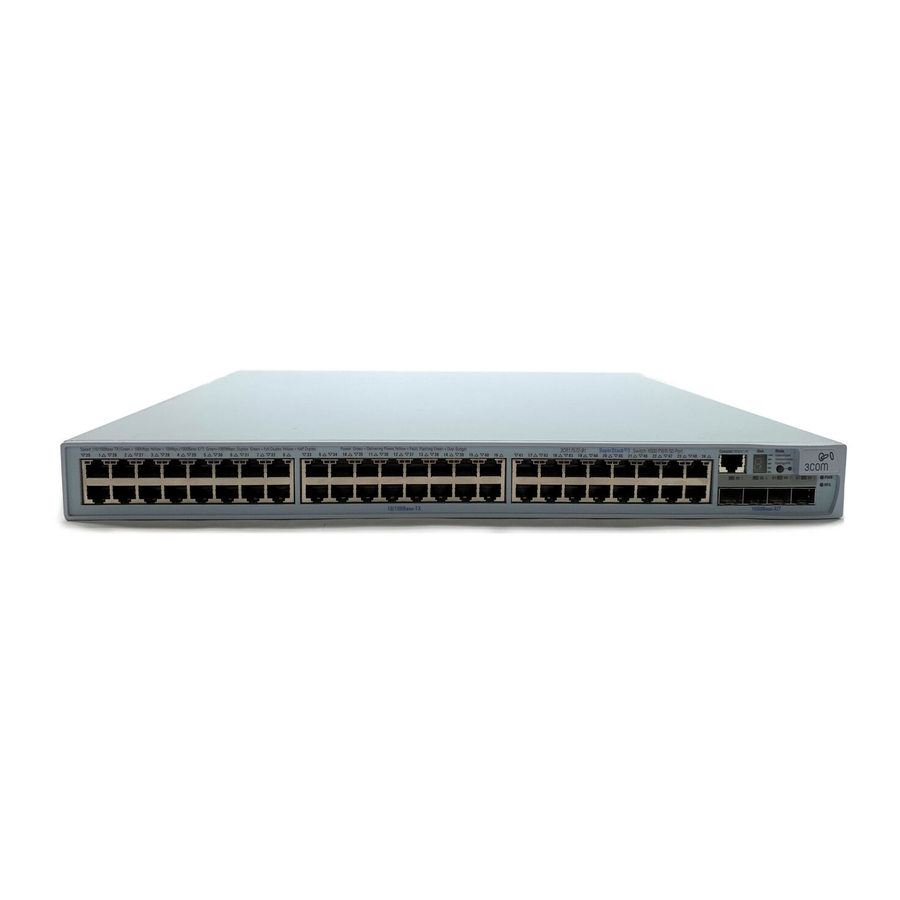
Table 2 Hardware Features (Continued) Feature SFP Ethernet Ports Mounting Clustering Switch 4500G Figure 1 describes the front panel of the Switch 4500G 24-Port unit. 24-Port and Switch Figure 1 Switch 4500G 24-Port—front panel 4500G 48-Port—Front and Rear Panel Detail... - Page 12 1: I HAPTER NTRODUCING THE WITCH Figure 2 describes the rear panel of the Switch 4500G 24-Port unit. Figure 2 Switch 4500G 24-Port—rear panel (1) AC power input (3) Grounding terminal (5) Extended slot 2 Figure 3 describes the front panel of the Switch 4500G 48-Port unit.
-
Page 13: Leds Of Switch 4500G 24-Port And Switch 4500G 48-Port Switch
Figure 4 describes the rear panel of the Switch 4500G 48-Port unit. Figure 4 Switch 4500G 48-Port—rear panel (1) AC power input (3) Grounding terminal (5) Extended slot 2 LEDs of Switch The Switch 4500G 24-Port/Switch 4500G 48-Port Ethernet Switch provides 4500G 24-Port and LEDs on the front panel for your convenience to monitor the switch. - Page 14 1: I HAPTER NTRODUCING THE WITCH Table 3 Description on the LEDs of the Switch 4500G 24-Port/Switch 4500G 48-Port Ethernet Switch (Continued) Module LED 7-segment digitron display 4500G F AMILY Label Status Module Green, ON (MOD) Yellow, blinking Unit POST...
- Page 15 LEDs of Switch 4500G 24-Port and Switch 4500G 48-Port Switch Table 3 Description on the LEDs of the Switch 4500G 24-Port/Switch 4500G 48-Port Ethernet Switch (Continued) Label Status 10/100/1000 Rate BASE-T mode Ethernet port status LED Duplex mode 1000Base SFP...
-
Page 16: Switch 4500G Pwr 24-Port And 48-Port -Front And Rear Panel Detail
1: I HAPTER NTRODUCING THE WITCH Figure 5 describes the front panel of the Switch 4500G PWR 24-Port unit. Figure 5 Front Panel of the Switch 4500G PWR 24-Port Ethernet Switch (1) 10/100/1000 BASE-T autosensing Ethernet port status LEDs (3) Console port... - Page 17 Switch 4500G PWR 24-Port and 48-Port —Front and Rear Panel Detail Figure 7 describes the front panel of the Switch 4500G PWR 48-Port Ethernet Switch. Figure 7 Front panel of the Switch 4500G PWR 48-Port Ethernet Switch (1) 10/100/1000 BASE-T autosensing...
-
Page 18: Switch 4500G Pwr 24-Port And 48-Port Indicators
1: I HAPTER NTRODUCING THE WITCH Table 4 describes the Ethernet Switch LEDs. Table 4 Description on the LEDs of the Switch 4500G PWR 24-Port& 48-Port Ethernet Switch Mode LED Power LED Module LED 4500G F AMILY Switch 4500G PWR 24-Port/Switch 4500G PWR 48-Port... - Page 19 Switch 4500G PWR 24-Port and 48-Port Indicators Table 4 Description on the LEDs of the Switch 4500G PWR 24-Port& 48-Port Ethernet Switch (Continued) Label Status 7-segment Unit POST digitron running display POST failed Loading software Fan failure Overtemper ature alarm...
- Page 20 1: I HAPTER NTRODUCING THE WITCH Table 4 Description on the LEDs of the Switch 4500G PWR 24-Port& 48-Port Ethernet Switch (Continued) 10/100/1000 BASE-T Ethernet port status LED 4500G F AMILY Label Status None Rate mode Green Yellow Yellow, blinking (3 Hz)
- Page 21 Switch 4500G PWR 24-Port and 48-Port Indicators Table 4 Description on the LEDs of the Switch 4500G PWR 24-Port& 48-Port Ethernet Switch (Continued) Label Status 10/100/1000 None PoE mode BASE-T (continued) Ethernet port status LED (continued) 1000 Base None This LED is...
-
Page 22: System Specifications Of The Switch 4500G Series
1: I HAPTER NTRODUCING THE WITCH Table 5 contains the system specifications of the Switch 4500G series switches. Table 5 System specifications of the Switch 4500G series switches Item Physical dimensions (H W D) Weight Console port GE ports on... - Page 23 System Specifications of the Switch 4500G Series Table 5 System specifications of the Switch 4500G series switches (Continued) Switch 4500G 24-Port Item 3CR17761-91 Power 80 W consumption (full load) Operating 0°C to 45°C (32°F to 113°F) temperature Relative 10% to 90%...
- Page 24 1: I 4500G F HAPTER NTRODUCING THE WITCH AMILY...
-
Page 25: Installing The Switch
WARNING: Safety Information. Before you install or remove any components from the Switch or carry out any maintenance procedures, you must read the 3Com Switch Family Safety and Regulatory Information document enclosed. AVERTISSEMENT: Consignes de securite. Avant d'installer ou... -
Page 26: Rack-Mounting The Switch
2: I HAPTER NSTALLING THE WITCH CAUTION: Opening the switch or tampering with the warranty sticker can void your warranty. Follow the steps below to mount your switch in a standard 19-inch rack: 1 Check that the rack is sturdy and properly grounded. Attach the rack-mount brackets to the front or rear panel of the chassis with screws. - Page 27 Front mount angle Mounting the rear bracket The Switch 4500G 24-Port and Switch 4500G 48-Port series do not need rear brackets. The description on mounting rear brackets is only for the Switch 4500G PWR 24-Port and Switch 4500G PWR 48-Port series.
- Page 28 2: I HAPTER NSTALLING THE WITCH Figure 12 Positions for screw mounting on the switch Follow the steps below to mount the rear bracket: 1 Use screws to fix the rear bracket to the rear mount angle. 2 Determine the position for screw mounting on the switch according to the position of the mount angle.
-
Page 29: Mounting The Switch On A Desktop
Figure 14 Installation completed 2 Screw 1: Fix the rear bracket to the mount angle. Mounting the In many cases, standard 19-inch racks are not available. Therefore, switches Switch on a are often placed on a desktop. To place your switch on a desktop, you Desktop simply need to: ■... -
Page 30: Connecting The Ground Wire
2: I HAPTER NSTALLING THE WITCH Figure 15 Power socket (recommended) Neutral point Neutral point Zero line Zero line Connecting the AC Power Cord 1 Connect one end of the chassis ground wire to the grounding screw on the rear of the chassis and the other end to the ground as near as possible. 2 Connect one end of the power cord to the power input on the rear panel of the chassis, and plug the other end to the AC power input of the power source. - Page 31 Note: The fire main and lightning rod of a building are not suitable for grounding the switch. The ground wire of the switch should be connected to the grounding device for the equipment room. Figure 16 Ground the switch through a grounding strip (1) Power input on the switch (3) Protection ground wire 2 When there is no grounding strip but earth is available near the installation...
- Page 32 2: I HAPTER NSTALLING THE WITCH Figure 17 Ground the switch by burying the grounding body into the earth ( 1 ) ( 1 ) ( 1 ) ( 1 ) (1) Power input on the switch (4) Ground 3 For an AC-powered switch, if neither of the above-mentioned two conditions is available, ground the switch through PE wire of the AC power supply.
-
Page 33: Connecting Console Cable
Connecting Console Cable Console Cable A Console cable is an 8-core cable. One end of the cable is a crimped RJ-45 connector for the connection to the Console port of the switch, and the other end is a DB-9 female connector for the connection to the serial port on the Console terminal, as shown in Figure 19. -
Page 34: Connecting Console Cable
2: I HAPTER NSTALLING THE WITCH Connecting Console When you want to use the terminal to configure the switch, follow these Cable steps to connect a terminal device to your switch using console cables: 1 Plug the DB-9 female connector of the Console cable to the serial port of the PC or terminal where the switch is to be configured. -
Page 35: Setting U P For Management
ETTING P FOR To make full use of the features offered by your switch, and to change and monitor the way it works, you have to access the management software that resides on the switch. This is known as managing the switch. Managing the switch can help you to improve the efficiency of the switch and therefore the overall performance of your network. -
Page 36: Methods Of Managing A Switch
3: S HAPTER ETTING P FOR ANAGEMENT To manage your switch you can use one of the following methods: Command line interface management ■ Command line interface management using SSH ■ Web interface management ■ SNMP management ■ Command Line Each switch has a command line interface (CLI) that allows you to manage Interface the switch from a workstation, either locally using a console port... -
Page 37: Command Line Interface Management Using Ssh
This view enables you to configure the system parameters. To display this view, from user view enter system-view. The prompt for system view is [4500G]. Command Line The Switch 4500G supports Secure Shell version 2.0 (SSHv2.0), allowing Interface secure access to the Command Line Interface of the switch. Management using... -
Page 38: Snmp Management
You can manage a switch using any network management workstation running the Simple Network Management Protocol (SNMP) as shown in Figure 23. For example, you can use the 3Com Network Director software, available from the 3Com website. Figure 23 SNMP Management over the Network SNMP Network Management Refer to “Setting Up SNMP Management V1 or V2”... - Page 39 DHCP See page 40 Do you want to manually configure the IP information? How do you want to view the automatically configured IP information? Use 3Com Network Director (3ND). See page 49 Interface. See page 42 SNMP Web Interface...
-
Page 40: Ip Configuration
(Static IP addresses are necessary to ensure that the switch is always allocated the same IP information.) For most installations, 3Com recommends that you configure the switch IP information manually. This makes management simpler and more reliable as it is not dependent on a DHCP or BootP server, and eliminates the risk of the IP address changing. -
Page 41: Preparing For Management
“Methods of Managing a Switch” on page 36. For detailed information about the specific web interface operations and command line interface commands and problem solving, refer to the “Switch 4500G Command Reference Guide” on the 3Com Web site. Setting Up Overview... -
Page 42: Manually Configuring Ip Information
3: S HAPTER ETTING P FOR ANAGEMENT You can manually configure the switch IP information in the following ways: Connecting to the console port ■ Connect a workstation using a console cable to the console port of the switch. You can then manually enter IP information using the command line interface (CLI). - Page 43 Refer to the documentation that accompanies the terminal emulation software for more information. 3 Power up the switch. The Power on Self Test (POST) will now be performed. The Switch 4500G takes approximately one minute to boot. Manually Configuring IP Information Switch...
- Page 44 2 At the login and password prompts, enter press Return and at the password prompt press Return again. If you have logged on correctly, <4500G> should be displayed as shown in Figure 26. Once you have logged in you will automatically be in User View.
-
Page 45: Connecting To A Front Panel Port
3 Enter the system-view command and press Return. To confirm that you are in the System View, the following should be displayed: [4500G] Enter interface vlan 1 and Enter. 4 Enter the IP address and subnet mask for the switch as follows: ip address xxx.xxx.xxx.xxx mmm.mmm.mmm.mmm... - Page 46 3: S HAPTER ETTING P FOR ANAGEMENT A Category 5 twisted pair Ethernet cable with RJ-45 connectors at both ■ ends. A suitable Web browser. Refer to “Choosing a Browser”on page 53. ■ Existing IP address of the switch. ■ You need to have the following so that you can manually set up the ■...
- Page 47 Setting Up the Switch with IP Information You are now ready to manually set up the switch with IP information. You can do this using the Web interface or the command line interface (CLI) using telnet. Using the Web Interface 1 Power-up the switch.
- Page 48 3 At the login and password prompts, enter admin as your user name and press Return at the password prompt. If you have logged on correctly, <4500G> is displayed as shown in the example in Figure 28. Figure 28 User View Login using Telnet 4 Enter the system-view command and Enter.
-
Page 49: Viewing Automatically Configured Ip Information
DHCP or BootP server. If your network does not have a DHCP or BootP server, the workstation running 3Com Network Director must be on the same subnet as the switch, because Auto-IP addresses are non-routable. Connecting to the... - Page 50 3 At the login and password prompts, enter press Return at the password prompt. If you have logged on correctly, <4500G> is displayed as shown in the example in Figure 29. Figure 29 User View Login 4 Enter display ip interface br to view a summary of allocated IP addresses.
-
Page 51: Setting Up Command Line Interface Management
Setting Up This section describes how you can set up command line interface Command Line management using a local console port connection or over the network. Interface Management User Interface User interface configuration is provided by the switch to configure and Overview manage the port data. -
Page 52: Setting Up Command Line Interface Management Using Ssh
6 If you have logged on correctly, the switch you want to manage is displayed as <4500G>, as shown in Figure 26 on page 44. In order to set up command line interface management using SSH, refer to the “3Com®... -
Page 53: Web Management Over The Network
Choosing a Browser To display the web interface correctly, use one of the following Web browser and platform combinations: Table 7 Supported Web Browsers and Platforms Browser Netscape 7.1 Internet Explorer 5.5 Yes Internet Explorer 6.0 Yes Mozilla 1.4 For the browser to operate the web interface correctly, JavaScript™ and Cascading Style Sheets must be enabled on your browser. -
Page 54: Setting Up Snmp Management V1 Or V2
VLAN 1 (the Default VLAN). By default, all ports on the switch are in VLAN 1. You can use the 3Com Network Director application that is available from the 3Com website to provide SNMP management for your switch. If you use 3Com Network Director it automatically loads the correct MIBs and necessary files onto your workstation. -
Page 55: Default Users And Passwords
To manage your switch using an SNMP network management application, you need to specify SNMP community strings for the users defined on the switch. You can do this using the command line interface system management snmp community command. Refer to the command line interface section of the “SuperStack 4 Switch Command Reference Guide”... - Page 56 P FOR ANAGEMENT To set a password for the admin user in the CLI, enter the following from system view: [4500G]local-user admin <cr> [4500G-luser-admin]password simple xxxxxxxx (where xxxxxxxx is your chosen password). Save the configuration in the User View. For information on the lost password procedure please refer to the...
-
Page 57: Problem Solving
■ If you experience a problem that is not listed here, it may be included in the Support section of the switch 4500G Command Reference Guide on the CD-ROM that accompanies your switch. For Technical Support information, see Appendix D. -
Page 58: Solving Problems Indicated By Leds
4: P HAPTER ROBLEM OLVING If the LEDs on the switch indicate a problem, refer to the list of suggested solutions below. The PWR LED does not light Check that the power cable is firmly connected to the switch and to the supply outlet. -
Page 59: Solving Hardware Problems
Solving Hardware In the rare event of your switch unit experiencing a hardware failure, refer Problems to the list of suggested solutions below. A fan failure warning message is received Your switch has a fan monitoring system that will generate fan failure warning messages. - Page 60 3 Power cycle the unit. To do this, remove and reconnect the AC mains supply. If another fan failure warning message is generated using the Command Line Interface or the Web interface, return the unit to 3Com. Unit fails, no SNMP fan failure message is received 1 Power cycle the unit.
-
Page 61: Solving Communication Problems
IP address of the router. The switch’s IP address has been entered correctly in your network management application (such as 3Com Network Director). The first part (‘192.168.100’ in the example) identifies the network on which the device resides The second part (‘.8’... -
Page 62: Solving Fabric Formation Problems
If your IP network is internal to your organization only, that is, you do not access the Internet, you may use any arbitrary IP address as long as it is not being used by another device on your network. 3Com suggests you use addresses in the range 192.168.0.0 to 192.168.255.255 with a subnet mask of 255.255.255.0. -
Page 63: Upgrading Software
PGRADING This chapter describes how to upgrade software to your Switch 4500G. It covers the following topics: Upgrading from the Command Line Interface ■ Upgrading from the Bootrom Interface ■ Bootrom Upgrade ■ OFTWARE... -
Page 64: Upgrading From The Command Line Interface
5: U HAPTER PGRADING OFTWARE This section describes how to upgrade files to your switch from the Command Line Interface (CLI). Introduction Before upgrading the software to your switch from the CLI, it is important to check the contents of the flash to ensure that there is enough space to download the new files. - Page 65 3 Any additional files should be considered for deletion to allow maximum space for downloading the new files. To delete a file from the list enter: delete/unreserved unit1>flash:/ To delete files from the list for the remaining units in a fabric, replace unit1 with unit2 (on the next line) and so on for each switch in the fabric.
-
Page 66: Tftp
(where aaa.aaa.aaa.aaa is the IP address of the TFTP server) and s4a indicates the switch filename. see Table 9 for further details. Table 9 Switch 4500G Filenames Filename Prefix 2 To download the Web user interface file, enter: tftp aaa.aaa.aaa.aaa get http.zip... - Page 67 3 To copy the new Web user interface file to each switch in the fabric, enter: copy unit1>flash:/http.zip unit2>flash:/ Replace unit2 with unit3 and so on for each switch in the fabric. 4 To copy the new Bootrom firmware file to each switch in the fabric, enter: copy unit1>flash:/s4e002_012_000.btm unit2>flash:/ Replace unit2 with unit3 and so on for each switch in the fabric.
-
Page 68: Ftp (Using A Network Port)
5: U HAPTER PGRADING OFTWARE FTP (using a network To upgrade software to your switch using FTP do the following: port) 1 Enter the following command from User View: ftp aaa.aaa.aaa.aaa (where If the FTP server has been successfully located, the following information is displayed: Trying... -
Page 69: Xmodem (Using The Console Cable)
XModem (using the To upgrade software to your switch using XModem do the following: console cable) 1 From the User View, enter: xmodem get unit1>flash:/3ComOScfg.def The following information is displayed: **** WARNING **** xmodem is a slow transfer protocol limited to the current speed settings of the auxiliary ports. -
Page 70: Upgrading From The Bootrom Interface
5: U HAPTER PGRADING OFTWARE This section describes how to upgrade your switch from the Bootrom Interface. Introduction When the switch is running the initial boot phase using the console, the following prompt is displayed with a five second countdown timer: Press CTRL-B to enter Boot Menu... - Page 71 3 Select option 3 from the Boot Menu. A file list similar to the following is displayed: Boot menu choice: 3 File Number File Size(bytes) File Name ==================================================== 3(*) 4649088 576218 10301 10369 10369 Free Space: 10469376 bytes The current application file is s4b03_01_00s168.app (*)-with main attribute;...
-
Page 72: Tftp
5: U HAPTER PGRADING OFTWARE TFTP To upgrade software to your switch using TFTP, do the following: 1 From the Boot Menu, select option 1 (Download application file to flash) to display the following: 1. Set TFTP protocol parameter 2. Set FTP protocol parameter 3. -
Page 73: Ftp
To upgrade software to your switch using FTP, do the following: 1 From the Boot Menu, select option 1 (Download application file to flash) to display the following: 1. Set TFTP protocol parameter 2. Set FTP protocol parameter 3. Set XMODEM protocol parameter 0. -
Page 74: Xmodem
5: U HAPTER PGRADING OFTWARE XModem To upgrade software to your switch using XModem, do the following: 1 From the Boot Menu, select option 1 (Download application file to flash) to display the following: 1. Set TFTP protocol parameter 2. Set FTP protocol parameter 3. -
Page 75: Bootrom Upgrade
Bootrom Upgrade This section describes how to indicate which file the switch is to boot from once the software has been loaded. 1 From the Boot menu, select option 2 to display the following: Select application file to boot: 1. set application file to boot 2. -
Page 76: Bootrom Upgrade Using Tftp
5: U HAPTER PGRADING OFTWARE Bootrom Upgrade To upgrade the bootrom firmware from the Boot menu using TFTP do the using TFTP following: 1 From the Boot menu, select option 6 to display the bootrom upgrade menu as shown: Bootrom update menu: 1. -
Page 77: Bootrom Upgrade Using Xmodem
2 Select option 2 to display the following: Load File name: Switch IP address: Server IP address: FTP User Name: FTP User Password: 3 Enter the file name, Switch IP address, Server IP address, FTP user name and password to display the following: Are you sure to update your bootrom? Yes or No(Y/N) 4 Enter y and the following information is displayed to indicate the file is downloading:... - Page 78 5: U HAPTER PGRADING OFTWARE 4 Press Enter to start the download. The following information is displayed: Now please start transfer file with XMODEM protocol If you want to exit, Press <Ctrl+X> Loading ...CCCCCCCCCCCCCCCCCCCCCCCCCCCCC 5 As the file is downloading, start the XModem send file process with terminal emulation software, such as Microsoft Hyperterminal.
-
Page 79: Null Modem Cable
Null Modem Cable PC-AT Serial Cable OUTS RJ-45 to RS-232 25-pin Switch 5500 Cable connector: RJ-45 female Screen Shell Ground RJ-45 to 9-pin Switch 5500 Cable connector: RJ-45 female Screen Shell Ground PC/Terminal Cable connector: 25-pin male/female Screen only required if screen always required Ground required for handshake... -
Page 80: Modem Cable
A: P PPENDIX OUTS RJ-45 to RS-232 25-pin Switch 5500 Cable connector: RJ-45 female Screen Ground 10/100 and 1000BASE-T RJ-45 connections. Table 10 Pin assignments Pin Number Ports configured as MDI RS-232 Modem Port Cable connector: 25-pin male Shell 10/100 Transmit Data + Transmit Data −... - Page 81 Table 11 Pin assignments Pin Number 10/100 Ports configured as MDIX Receive Data + Receive Data − Transmit Data + Not assigned Not assigned Transmit Data − Not assigned Not assigned Ethernet Port RJ-45 Pin Assignments 1000 Bidirectional Data B+ Bidirectional Data B−...
- Page 82 A: P PPENDIX OUTS...
-
Page 83: Specifications
−10 ° to +70 °C (14 ° to 158 °F) Storage Temperature Operating Humidity 95% non-condensing Standards EN60068 to 3Com schedule (Package testing: paras 2.1, 2.2, 2.30, and 2.32. Operational testing: paras 2.1, 2.2, 2.30 and 2.13). Safety Agency Certifications UL 60950-1, EN 60950-1, CSA 22.2 No. -
Page 84: Switch 4500G 48-Port
0 ° to 40 °C (32 ° to 104 °F) −10 ° to +70 °C (14 ° to 158 °F) 95% non-condensing EN60068 to 3Com schedule (Package testing: paras 2.1, 2.2, 2.30, and 2.32. Operational testing: paras 2.1, 2.2, 2.30 and 2.13). -
Page 85: Switch 4500G Pwr 24-Port
0 ° to 40 °C (32 ° to 104 °F) −10 ° to +70 °C (14 ° to 158 °F) 95% non-condensing EN60068 to 3Com schedule (Package testing: paras 2.1, 2.2, 2.30, and 2.32. Operational testing: paras 2.1, 2.2, 2.30 and 2.13). -
Page 86: Witch 4500G Pwr 48-Port
0 ° to 40 °C (32 ° to 104 °F) −10 ° to +70 °C (14 ° to 158 °F) 95% non-condensing EN60068 to 3Com schedule (Package testing: paras 2.1, 2.2, 2.30, and 2.32. Operational testing: paras 2.1, 2.2, 2.30 and 2.13). -
Page 87: Grounding Lead
Grounding Lead Safety Requirements Voltage Rating Insulation Thickness Insulation Colour The Grounding Cable (in PWR Units only) shall comply with the following safety standards: UL Subject 758, UL 1581 and CSA C22.2 No. 210 UL VW-1 and CSA FT1 Vertical Flame Test 600V 0.4mm Green/Yellow... - Page 88 B: T PPENDIX ECHNICAL PECIFICATIONS...
-
Page 89: Register Your Product To Gain Service Benefits
To take advantage of warranty and other service benefits, you must first register your product at: http://eSupport.3com.com/ 3Com eSupport services are based on accounts that are created or that you are authorized to access. 3Com offers the following support tool: 3Com Knowledgebase —... -
Page 90: Contact Us
3Com or your reseller. Support contracts that include software upgrades cover feature enhancements, incremental functionality, and bug fixes, but they do not include software that is released by 3Com as a separately ordered product. Separately orderable software releases and licenses are listed in the 3Com Price List and are available for purchase from your 3Com reseller. -
Page 91: Telephone Technical Support And Repair
■ ■ ■ To send a product directly to 3Com for repair, you must first obtain a return materials authorization number (RMA). Products sent to 3Com without authorization numbers clearly marked on the outside of the package will be returned to the sender unopened, at the sender’s expense. - Page 92 Return material authorization: warranty_repair@3com.com Contract requests: emea_contract@3com.com Latin America — Telephone Technical Support and Repair Antigua 1 800 988 2112 Argentina 0 810 444 3COM Aruba 1 800 998 2112 Bahamas 1 800 998 2112 Barbados 1 800 998 2112 Belize...